
[Praburaja, 2(6): June, 2013]
ISSN: 2277-9655
IJESRT
INTERNATIONAL JOURNAL OF ENGINEERING SCIENCES & RESEARCH TECHNOLOGY
A Cascaded Quasi Z-Source Scheme Step up DC-DC Converter Using ANN Based Control
*1,2
R.Praburaja*1, C.Karthikeyan2 Department of EEE, K.S.R. College of Engineering, Tiruchengode, India rpraburaja@https://www.doczj.com/doc/278122609.html, Abstract
Modern renewable generation systems need smart and integrated power converters ensure for high efficiency of power conversion .This project intends to the Artificial Neural Network (ANN) based control step up DC-DC converter family with a cascaded Quasi Z-source network (qZS-scheme).The cascaded (two-stage) qZSnetwork could be derived by the adding of one diode, one inductor, and two capacitors to the traditional single stage quasi-Z-source inverter (qZSI). The proposed cascaded qZSI giving as same all the advantages of the traditional solution (voltage boost and buck functions in a single stage, continuous input current ,and improved reliability).As compared to the conventional qZSI, the proposed solution reduces the shoot-through duty cycle at the same voltage boost factor ,and without adding additional switches. The ANN based controller ensuring the better result compare to the conventional PI controller .The two-stage qZSI in the shoot-through and non-shoot-through operating modes are described. The proposed and conventional closed loop results are compared. Keywords : Quasi Z-Source Inverter, VDR, DC-DC conversion, Artificial Neural Network.
Introduction
The voltage-fed (DC-link) Quasi Z-source Inverter (qZSI) has been mainly suitable for different renewable wide varying source (DC-link) applications (Fuel Cells (FC), Solar panels, wind power generators, etc.) because of its unique capability of voltage boost and buck functions in a single stage. This switching state is forbidden for the traditional voltage-source inverters (VSI) because it causes the short circuit of the DC-link capacitors. If the input voltage is high enough voltage, the shoot-through states to be eliminated, and the qZSI begins to operate as a normal VSI. To improve the performance of voltage-fed qZSI with continuous input current gained by the introducing cascaded quasi Z-source network (qZS-network).The cascaded (two-stage) qZS-network is derived by the adding of one diode ( ), one inductor ), and two capacitors ( ), and ) to the traditional single stage qZSI system. Quasi Z-source inverter (qZSI) is a new promising power conversion technology perfectly suitable for interfacing of renewable (i.e., photovoltaic, wind turbines) and alternative (i.e., fuel cells) energy sources. Boost-buck function by the one-stage conversion. Continuous input current (input current never drops to zero, thus featuring the reduced stress of http: // https://www.doczj.com/doc/278122609.html, the input voltage source, which is especially topical in such demanding applications as power conditioners for fuel cells and solar panels). Excellent reliability due to the shoot-through withstanding capability. Low or no in-rush current during start up. Low common-mode noise. The qZSI are used in a vital role in a DC-DC converter system for continuous and better output shown in Figure 1.
Fig 1: Single stage qZSI Step up DC-DC converter system
However, the efficiency and voltage gain of the qZSI are limited and comparable with the conventional system of a voltage source inverter with the auxiliary step-up DC/DC converter in the input stage. The concept of extending the qZSI gain without increasing the number of active switches. These new converter topologies are commonly referred to cascaded qZSI and could be generally
(C) International Journal of Engineering Sciences & Research Technology [1492-1501]
[Praburaja, 2(6): June, 2013] classified as capacitor assisted and diode assisted topologies. In this paper cascaded qZSI with continuous input current will be presented with the ANN (Artificial Neural Network) based controlled step up DC-DC converter system.
ISSN: 2277-9655
shoot-through states are eliminated and ZSI begins to operate as traditional VSI. A drawback of the voltage-fed ZSI is a discontinuous input current during the shoot-through (boost conversion) mode. In additional the problem the voltage-fed quasi-Z-source inverter (qZSI) with a continuous input current to be introduced as a modification of a currently popular voltage-fed ZSI . This qZSI could be derived from ZSI simply by the transformation presented in Fig. 2. The voltage-fed qZSI features a main advantage of the normal ZSI – the single stage boost-buck conversion. Based on presented transformation one should notice the presence of input inductor L1 in the qZSI. This inductor buffers source current. Moreover, voltage of the capacitor C2 is lower than in case of basic ZSI system.
Operation Principles of Converter
Fig 2: Derivation of qZ-inverter: basic Z-source inverter ((a) and qZ-source inverter (b) (c).
The purpose of DC-DC converters is to supply a regulated DC output voltage to a variableload resistance from a fluctuating DC input voltage. In many cases the DC input voltage is obtained by rectifying a line voltage that is changing in magnitude. The DC-DC converters are commonly used in applications requiring regulated DC supply, such as computers, medical instrumentation, communication devices, television receivers, and battery chargers. The voltage-fed Z-source inverter (ZSI, Fig. 2(a) has been reported to be suitable for different renewable power applications (solar panels, wind power generators and more because of the unique capability of voltage boost and buck functions in a single stage. If necessary, the ZSI can boost the input voltage by introduce a special shoot-through switching state, which is the simultaneous conduction (cross conduction) of both switches of the same phase leg of the inverter. This switching state is forbidden for the traditional voltage source converters (VSI) because it causes the short circuit of the DC-link capacitors. It the ZSI, the shoot-through states are used to boost the magnetic energy stored in the DC side inductors L1 and L2 without short-circuiting the DC capacitors C1 and C2. This increase in inductive energy in turn provides the boost of voltage seen on the inverter output during the traditional operating states of the inverter. If the input voltage is high enough states of the inverter. If the input voltage is high enough the http: // https://www.doczj.com/doc/278122609.html,
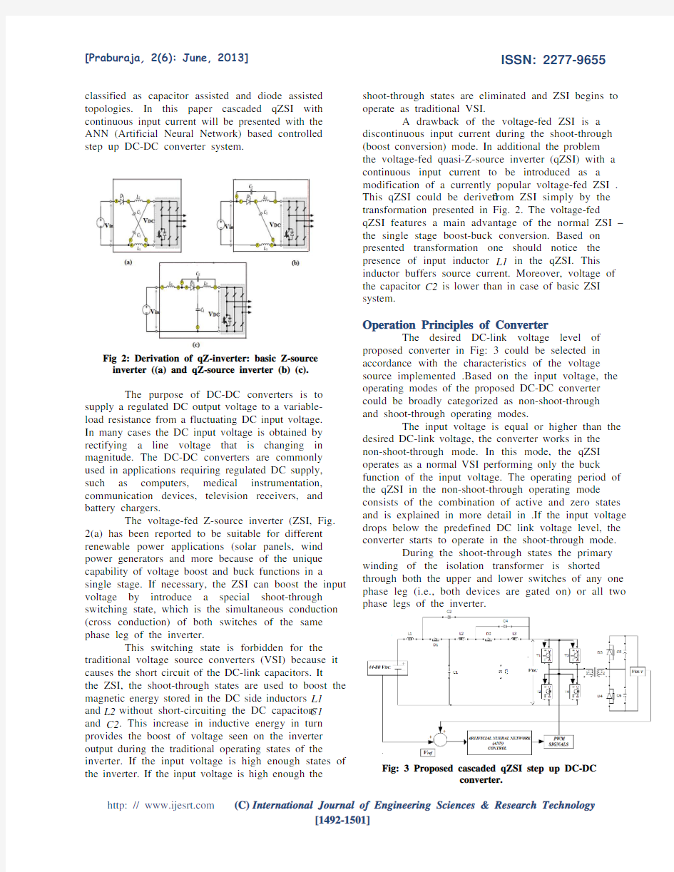
The desired DC-link voltage level of proposed converter in Fig: 3 could be selected in accordance with the characteristics of the voltage source implemented .Based on the input voltage, the operating modes of the proposed DC-DC converter could be broadly categorized as non-shoot-through and shoot-through operating modes. The input voltage is equal or higher than the desired DC-link voltage, the converter works in the non-shoot-through mode. In this mode, the qZSI operates as a normal VSI performing only the buck function of the input voltage. The operating period of the qZSI in the non-shoot-through operating mode consists of the combination of active and zero states and is explained in more detail in .If the input voltage drops below the predefined DC link voltage level, the converter starts to operate in the shoot-through mode. During the shoot-through states the primary winding of the isolation transformer is shorted through both the upper and lower switches of any one phase leg (i.e., both devices are gated on) or all two phase legs of the inverter.
Fig: 3 Proposed cascaded qZSI step up DC-DC converter.
(C) International Journal of Engineering Sciences & Research Technology [1492-1501]
[Praburaja, 2(6): June, 2013]
ISSN: 2277-9655
Modes of Operations
(a)Mode-I Non Shoot Through Mode In the non-shoot through mode Fig:4, the qZSI performs only the voltage buck function. This operation mode is typically used during light-load conditions, when the DC-link voltage reaches its maximum.
Fig: 6 Equivalent circuit for Shoot- through state.
This increase in the magnetic energy in turn provides the boost of the voltage seen on the Inverter output during the active states. The equivalent circuit of the two- stage qZSI during the shoot-through states is shown in Fig 6.
Fig: 4 Equivalent circuit for non shoot-through mode
Fig: 7 Inverter During shoot shoot state Fig: 5 (a) Inverter During positive half-cycle (b) Inverter during negative half-cycle.
During the shoot-through states, the primary winding of the isolation transformer is shorted through all switches of both phase legs shown in Fig: 7.
The inverter is controlled in the same manner as with the normal VSI, utilizing only the active states when only one switch in each phase leg conducts. (b )Mode -II Shoot Through State: When the input voltage drops below some predefined value, the qZSI starts to operate in the shoot-through mode. In order to boost the input voltage during this mode, a special switching state the shoot-through state is implemented in the pulse width modulation (PWM) inverter control. This shoot-through state is forbidden in the traditional VSIs because it would cause a short circuit of DC capacitors and destruction of power switches. The cascaded network makes the shoot-through states possible, effectively protecting the circuit from damage. Moreover, the shoot through states are used to boost the magnetic energy stored in the DC-side inductors , and without short circuiting the dc capacitors , . . ,. .
PWM Control Method
The control principle of the single-phase qZSI in the shoot-through (voltage boost) operating mode are shown in Fig: 8 and The Fig: 8 (a) shows the switching pattern of the normal single-phase VSI. These switching states are known as active states when one and only one switch in each phase leg conducts. To generate the shoot-through states, two reference signals ( and ) were introduced shown in Fig: 8(b). According to the presented control methodology (Fig: 8), the shoot-through states are created during the zero states of the full-bridge inverter, where the primary winding of the isolation transformer is shorted through either the top ( and ) or bottom ( and ) inverter switches. To provide a sufficient regulation margin, the zero-state time should always exceed the maximum duration
http: // https://www.doczj.com/doc/278122609.html,
(C) International Journal of Engineering Sciences & Research Technology [1492-1501]
[Praburaja, 2(6): June, 2013] of the shoot-through states period. , max per one switching
ISSN: 2277-9655
through time interval is evenly split into two intervals of half the duration. In that case, the operating frequency of qZS scheme will be two times higher, and the resulting switching frequency of the power transistors will be up to three times higher than the fundamental harmonic frequency of the isolation transformer. That fact is very relevant for proper component and operating frequency selection. In the operating points, when the input voltage is high enough, the shoot-through states are eliminated, and the qZSI operates as a normal VSI. Thus, the qZSI discussed could provide both the voltage boost and buck functions by the single stage energy conversion. The proposed cascaded qZS-network enables the duty cycle of the shoot-through state to be sufficiently decreased at the same voltage boost factor and component stresses as those of the traditional qZSI. Due to the decreased shoot through duty cycle, the values of the inductors and capacitors of the qZS-network could also be decreased. On the other hand, for the same component ratings and voltage and current stresses, the qZSI with the proposed cascaded qZS-network will ensure a higher voltage boost factor than with traditional solutions. (5) (a)Boost Factor In Cascaded Model:
Fig :8 Basic PWM switching wave form for qZSI.
If the triangle waveform is greater than or lower than , the inverter switches turn into the shoot-through state shown in Fig: 8(b). During this operating mode, the current through the inverter switches reaches its maximum. Depending on the control algorithm, the shoot-through current could be distributed between one or both inverter legs. The dclink voltage and the primary winding voltage waveforms of the isolation transformer during shootthrough are shown in Fig:8 (c) and (d), respectively. max (1) Thus, each operating period of the qZSI during the shoot through always consists of an active state , shoot-through state , and zero state
(2) Equation (ii) could also be represented as,
(3)
(4)
Fig: 9 PWM switching wave form for cascaded qZSI
Where is the duty cycle of an active state , is the duty cycle of a shoot-through state, and is the duty cycle of a zero state. It should be noted that the duty cycle of the shoot through state must never exceed 0.5 from the Fig: 9.It should be noted here that, in the presented control scheme, the shoothttp: // https://www.doczj.com/doc/278122609.html,
(6)
(7)
(C) International Journal of Engineering Sciences & Research Technology [1492-1501]
[Praburaja, 2(6): June, 2013]
ISSN: 2277-9655
From the equivalent circuit of the two-stage qZSI during the shoot-through state Fig: 6, the voltages of the inductors can be represented as,
(20) The peak dc-link voltage across the inverter bridge is,
(8) (21) (9) The resulting boost factor B of the input voltage is, (22) For the desired input voltage boost factor B, the duty cycle of the shoot-through state is calculated as, (23) Higher stage qZS-networks can be designed by just multiple repeating of the parts ? ? ? .For the nth stage qZS-network, the boost factor of the input voltage is calculated (24) From the equation (24) calculate number added stages of qZS to be finding out in this system.
(10) Let us consider that the duty cycles of the shoot-through and non-shoot-through states are and (1 ? ), correspondingly. At steady state, the average voltages of the inductors over one switching period are zero.
(11)
(12)
(13) From equation (5)-(13)
Isolation Transformer And Voltage Doubler Rectifier VDR
In this system transformer will “step-up” the ) of the voltage from the primary side ( transformer to the secondary side ( ) of the transformer. The second purpose of the transformer is to provide galvanic isolation between the primary and secondary. The galvanic isolation achieved by using the transformer is the greatest benefit of using a DCDC converter schemes. The operation and working principle are detailed in this converter system. A Voltage Doubler Rectifier (VDR) is an electronic circuit which charges capacitors from the input voltage and switches these charges in such a way that, in the ideal case, exactly twice the voltage is produced at the output as at its input as well as rectify the DC voltage to AC voltage. The VDR improves the rectification efficiency due to minimized voltage drops in the components (twice reduced number of rectifying diodes and full elimination of a smoothing inductor). Moreover, the VDR provides the demanded voltage doubling effect of the peak voltage of the secondary
(14)
(15)
(16)
(17) Solving (14)-(17) the voltages of capacitors C1, . . ,C4 could be found as
(18)
(19) http: // https://www.doczj.com/doc/278122609.html,
(C) International Journal of Engineering Sciences & Research Technology [1492-1501]
[Praburaja, 2(6): June, 2013] winding of the isolation transformer, thus ensuring the ripple free output voltage of 600 V at the rated power. To reduce the turns ratio of Isolation transformer VDR could be implemented on the secondary side of the converter. In contrast to the traditional full-bridge rectifier, two diodes of one leg in the VDR topology are replaced by the capacitors. Since each capacitor charges to the peak secondary voltage ( ) the output voltage from this circuit will be the sum of the two capacitor voltages or twice the peak voltage of the secondary winding.
ISSN: 2277-9655
technique to generate different training patterns and obtain the input data to ANN. (a)Implementation Of ANN Controller The soft computing techniques (ANN, Fuzzy Logic, Genetic Algorithms) are widely used for the controllers action instead of conventional control (P, PI, PID) controllers for better, exact results from the Linear, Non-Linear systems. In the conventional single stage model system of qZS step up DC-DC converter system PI controller for the closed loop voltage control from that system data has been collect for the ANN control system for train the neuron model. (b)Transfer Functions Transfer functions are the important constrain in the ANN controller design. Many transfer functions are included in the Neural Network. A complete list of them can be found in “Transfer Function Graphs” in the Neural Network. Two of the most commonly used functions are pure linear transfer function and sigmoid transfer function.
Artificial Nueral Network Control
Artificial Neural Networks (ANN) is one of the soft computing technique inspired by the structure and function of the human nervous system. There are many different types of ANN. Includes Hopfield, back propagation, linear vector quantization, artmap and many others. ANN act similar to the biological nueron system. Artificial neurons receive input from other neurons through a weighting function. This is usually an amplification or suppression of the signal. All of such signals connected to the neuron are added together. If this sum is higher than some threshold the neuron will fire and send out its own signal to other neurons. The output of the neuron is often determined by a sigmoid function of its input rather than the threshold function. This gives the neuron a non-linear input to output relationship. It should be noted that the knowledge is stored in the input weights of the neuron. Adjusting these weights give the neurons the ability to store different information. One neuron can’t store much information, but many neurons, interconnected in several layers can store much information.
Fig: 11 Transfer functions (a) Linear Function (b) Sigmoid Function
Fig 10: Block diagram of ANN controller
Artificial neural network (ANN)-based techniques have the potential advantage over conventional techniques in significantly improving the performance of the other techniques. This is so by virtue of the fact that ANNs have the capability of non-linear mapping, parallel processing and learning; these attributes make them ideally suited for power system control application. The block diagram of ANN-based algorithm for voltage and reactive power control in power systems is shown in Fig: 10. The method is based on using linear programming http: // https://www.doczj.com/doc/278122609.html, (C) International Journal of Engineering Sciences & Research Technology [1492-1501]
The Fig: 11(a) Illustrates the pure linear transfer function Neurons of this type are used in the final layer of multilayer networks that are used as function approximation (a=Pure linear of n) .It is widely used transfer function (-1 to +1) hard limit variations. Fig: 11(b) Illustrates the Sigmoid Function. The sigmoid transfer function takes the input, which can have any value between plus and minus infinity, and squashes the output into the range 0 to 1. The transfer functions are leads to develop the neuron by taking boundary of hard limits of output in the system. It’s obtained by means of classical control result analysis, or taking from the probability of result obtained from the system. (c)PI Controller Result From the resulting waveform (Figure: 5.4) of PI controller input, output variation in the closed loop voltage control to be calculated.
[Praburaja, 2(6): June, 2013]
ISSN: 2277-9655
[1100 1075 1050 1025 1000 975 950 925 900 875 850 825 800 775 750 Expected 725 700 675 650 625 600 575 550 525 500 475 450 425 400 375 350 values ( ) 325 300 275 250 225 200 175 150 125 100 75 50 25 0] [1056 1031 1006 981 956 931 906 881 856 831 806 781 756 731 706 Actual 681 656 631 606 581 556 531 506 481 456 431 406 381 356 331 306 values ( ) 281 256 231 206 181 156 131 106 81 56 31 6 -19 -44] Table 1 PI controller result comparison To implement each of these values to the equation (25) with weight ( ) and bias ) for the train the resulting voltages of the ANN controller. For example at value of (expected value at the table) means the actual could be trained by, (26) (27) (actual value in the table) (d)Program coding for ANN Controller p=[1100 1075 1050 1025 1000 975 950 925 900 875 850 825 800 775 750 725 700 675 650 625 600 575 550 525 500 475 450 425 400 375 350 325 300 275 250 225 200 175 150 125 100 75 50 25 0]; q=[ 1056 1031 1006 981 956 931 906 881 856 831 806 781 756 731 706 681 656 631 606 581 556 531 506 481 456 431 406 381 356 331 306 281 256 231 206 181 156 131 106 81 56 31 6 -19 -44]; net=newlin(p,t) net.iw{1}=1; net.b{1}=-44; net=train(net,p,t) gensim(net)
600 500 400 300 200 100 0 -100 -200
Voltage(Volts)
Input Output
0.2
0.4
0.6
0.8
1
1.2
1.4
1.6
1.8 x 10
2
5
Time(ms)
Fig: 12 PI controller Input , Output comparison
The input and output values are saturated at the point of (0,-44) and its saturation to be linear in the system. The most expected various values of voltages are to be taken for train the neural network and obtaining the result from the system. There are three distinct functional operations that take place in this simple neuron model (single perceptron) shown in Fig: 13. First, the scalar input p is multiplied by the scalar weight w to form the product wp, again a scalar. Second, the weighted input wp is added to the scalar bias b to form the net input n. (In this case, you can view the bias as shifting the function f to the left by an amount b. The bias is much like a weight, except that it has a constant input of 1.) Finally, the net input is passed through the transfer function f, which produces the scalar output a. The names given to these three processes are: the weight function, the net input function and the transfer function.
Fig: 13 simple neuron model
Simulation Results
MATLAB is an efficient way for designer to learn how a circuit and its control are working. It is normally much cheaper to do a thorough analysis than to build the actual circuit in which component stresses are measured. A simulation can discover the possible problems and determine optimal parameters, increasing the possibility of getting the prototype. New circuit concepts and parameter variations are easily tested. Destructive tests that cannot be done in the lab, either because of safety or because of costs involved, can easily be simulated. Matlab is the tool of choice for highproductivity research, development and analysis. Matlab features a family of add-on application-
(25) From the equation (25) the expected results could be derived by varying weight ) and bias values of the neuron. The set of expected and actual values (voltages) from PI controllers are shown in the table (1).
http: // https://www.doczj.com/doc/278122609.html,
(C) International Journal of Engineering Sciences & Research Technology [1492-1501]
[Praburaja, 2(6): June, 2013] specific solutions called toolboxes. Toolboxes are comprehensive collections of Matlab functions that extend the Matlab environment to solve particular classes of problems. Areas in which toolboxes are available include signal processing, control systems, neural networks, fuzzy logic, wavelets, simulation and many others. The Matlab version used here is 11.5.0. (a)Simulation Parameters The key parameters of the proposed converter are listed in the Table 2
Table: 2 Key Parameters of the Proposed Converter
ISSN: 2277-9655
Fig: 14 Simulation circuit for proposed Cascaded qZS scheme step up DC-DC Converter
Parameter Input voltage Output voltage Inductors in qZS scheme Capacitors in qZS scheme Output resistor Operating frequency of qZSI Isolation Transformer Capacitor in VDR Diodes of qZSSchemes Nominal frequency at Grid.
Symbol
Value (44-80)V 600V
,
33.5μH
180μF 10? 10kHz 1:3.75; 5 kHz 1200 μF 200V/71A
V T xP ( V o lts)
TF
The proposed Cascaded qZS scheme step up DC-Dc converter modeled in Matlab-Simulink environment shown in Fig: 14 and its parameters to be modified for obtaining the continuous output (600V) DC voltage from the wide varying source voltage (44V-80V). The variation of the source (DClink) voltage with the load, the output voltage of the step-up dc/dc converter could be kept constant simply by the variation of a shoot-through duty cycle For the control of the input voltage gain, a special shootthrough generation method by phase-shift modulation (PSM) to be implemented. The closed loop voltage control made by ANN controller it designed from the classical PI controller (For training the values).The converter simulated by the various conditions and obtaining the following simulation results. (b)Transformer Primary Voltage & Switching Pulse Signals
100 0 -100 0.5 1.5 1 0.5 0 1500 1.5 1 0.5 0 1500 1.5 1 0.5 0 1500 1.5 1 0.5 0 1500 1 1.5 2 2.5 3 3.5 4 4.5 x 10 5
4
Time(ms)
T1
1550
1600
1650
1700
1750
1800
1850
1900
1950
2000
Time(ms) T2
1550
1600
1650
1700
1750
1800
1850
1900
1950
2000
50HZ
T4
Time(ms)
1550
1600
1650
1700
1750
1800
1850
1900
1950
2000
Time(ms) T3
1550
1600
1650
1700
1750
1800
1850
1900
1950
2000
Time(ms)
Fig: 15 Simulation wave form for & Pulse Signals
http: // https://www.doczj.com/doc/278122609.html,
This waveforms are showing the primary voltage of the Isolation Transformer Primary ), and corresponding switching pulse signals for the qZSI. The reverse recovery time of the IGBTs and response (ON, OFF) are remarkable in this system. (C) International Journal of Engineering Sciences & Research Technology [1492-1501]
[Praburaja, 2(6): June, 2013] When the all switches turned ON (cross conduction of the switches),the Transformer voltage is absent and also it does not allows DC voltage across the primary so the circuit will closed and gives galvanic protection between the source side (qZSI) and the output (VDR) it is the major advantage to using the Isolation.
800 700 600 500
ISSN: 2277-9655
results indicating the useful power from the proposed system.
Conclusion
The cascaded qZSI offer a output voltage in a continuous and improved boost factor manner. This project has presented a implementation of a cascaded qZSI in order to the single stage model with same capacitor and inductor values and also same number of switches used in this system. Instead of PI controller ANN (Artificial Neural Network) has to be used for better closed loop performances avoids the time delay to reach the maximum output voltage. The proposed cascaded qZSI can be applied to almost all DC-DC, AC-DC, AC-AC, DC-DC power conversion schemes. The proposed configuration inherits all the advantages of traditional solutions (voltage boost and buck functions in a single stage, continuous input current, and improved reliability). Moreover, the voltage-fed qZSI with the cascaded qZS-network reduced the shoot-through duty cycle range at the same voltage boost factor and component stresses as the conventional qZSI. The proposed system ensures continuous input current of the converter during the shoot-through operating mode, thus featuring the reduced stress of the input voltage source, which is particularly used in such demanding applications as power conditioners for solar panels, fuel cell and wind power systems.
Vo (Volts)
400 300 200 100 0 -100
0
0.2
0.4
0.6
0.8
1
1.2
1.4
1.6
1.8 x 10
2
5
Time(ms)
Fig: 16Simulation waveform for existing single stage qZSI
V T X S ( V o lts)
VDR output voltage using PI controller Simulation waveform for single stage qZSI VDR output voltage using PI controller Fig:16 .This indicating the voltage deviation at the staring time. The simulation waveform of transformer secondary voltage ( ) shown in the Fig: 17. It never drops to zero at any input (44V-80V) wide variations. Transformer secondary voltage directly fed to the input of VDR.
200 0 -200 0 0.5 1 1.5 Time(ms) 2 2.5 x 10 3
4
References
[1] Vinnikov.D and Indrek Roasto (2011) ‘Quasi-Z-Source-Based Isolated DC/DC Converters for Distributed Power Generation’, IEEE Transactions on industrial electronics, vol. 58, no.1. [2] Aeenmehr.A, Sina.A and Mohamadian.H (2012) ‘Power System Voltage Control using LP and Artificial Neural Network’, World Academy of Science, Engineering and Technology [3] Eung-Ho Kim and Jong-Jae Lee (2008) ‘Dual Series-Resonant Active-Clamp Converter IEEE Trans. On Industrial Electronics’, Vol. 55, No. 2,699. [4] Fang Zheng Peng and Miaosen Shen (2008) ‘Operation Modes and Characteristics of the Z-Source Inverter With Small Inductance or Low Power Factor’, IEEE Trans. On Industrial Electronics, Vol. 55, No.1. [5] Fausett.L (1994) ‘Fundamentals of Neural Networks Architectures Algorithm and applications”, Printice Hall International
V o ( V o lts)
500 0
0
0.5
1
1.5
2
2.5 x 10
3
5
Time(ms) V r m s ( V o lts)
500 0 -500 0 0.05 0 -0.05 0 1000 2000 3000 4000 5000 6000 1000 2000 3000 4000 5000 6000
7000
Time(ms) Irm s (m A )
7000
Time(ms)
Fig: 17
,
,
,
Waveforms.
The simulation wave form of output voltage using ANN controller is shown in the Fig : 17 It achieves the maximum voltage at the instant of starting time itself. Simulation waveform for of grid at 50W Nominal power Shown in the Fig: 17.The results indicating the useful power from the proposed system. Simulation waveform for of grid at 50W Nominal power Shown in the Fig: 17.The http: // https://www.doczj.com/doc/278122609.html,
(C) International Journal of Engineering Sciences & Research Technology [1492-1501]
[Praburaja, 2(6): June, 2013] [6] Fang Zheng Peng (2003) ‘Z-Source Inverter’, IEEE Trans.On Industry Applications, Vol. 39, No. 2. [7] J.ZakisD,Vinnikov.D,I..Roasto (2010) ‘Softswitching capability analysis of a qZSIbased DC/DC converter’12th Biennial Baltic Electronics Conference (BEC2010) . [8] Heung-Geun Kim, Jong-Hyoung Park (2012) ‘Power Conditioning System for a Grid Connected PV Power Generation Using a Quasi-Z-Source Inverter’, On JPE 10-2K12 [9] Jin Wang, Joel Anderson and Ryan Buffen barger (2004) ‘Low Cost Fuel Cell Converter System for Residential Power Generation’, IEEE Trans. On Power Electronics, Vol. 19, No. 5. [10] Kamaraj.V, Shajith Ali.U (2011) ‘Z-Source Inverter with A New Space Vector PWM Algorithm For high Voltage Gain’, ISSN 1819-6608 Vol. 6,NO. 6. [11] Mazumder Sudip K ,Burra.Rajni K and Rongjun Huang (2010) ‘A Universal GridConnected Fuel-Cell Inverter for Residential Application’, IEEE Trans. On Industrial Electronics, Vol. 57, No. 10 . [12] Michael A. E. Andersen, Morten Nymand (2010) ‘High-Efficiency Isolated Boost DC– DC Converter for High-Power Low-Voltage Fuel-Cell Applications’, IEEE Transactions On Industrial Electronics, Vol. 57, No. 2. [13] Prasad N. Enjeti and Yu Jin Song (2004) ‘A High Frequency Link Direct DC-AC Converter for Residential Fuel Cell Power Systems’,35th Annual IEEE Power Electronics Conference. [14] Rajni K.Burra and Sudip K.Mazumder (2007) ‘A Ripple-Mitigating and EnergyEfficient FuelCell Power-Conditioning System’, IEEETrans. On Power Electronics, Vol. 22, No. 4. [15] Vinnikov. D, S.Ott (2011) ‘Extended Boost Quasi-Z-Source Inverters: Possibilities and Challenges’, ISSN 1392 – 1215 Electronics And Electrical Engineering 2011.No.6(112). [16] Weixiang X. Shen , Zhi Jian Zhou(2008) ‘Single-Phase Uninterruptible Power Supply Based on Z-Source Inverter’, IEEE Trans. On Industrial Electronics Vol. 55, No. 8.
ISSN: 2277-9655
http: // https://www.doczj.com/doc/278122609.html,
(C) International Journal of Engineering Sciences & Research Technology [1492-1501]
个人工作失误检讨书范文 个人工作失误检讨书范文 尊敬的部门领导: 首先我怀着愧疚和懊悔的心情为那天犯下的错误向您表示深刻的悔过。哪天由于自己工作上的失误,给部门造成了严重的影响和不良后果,并造成您工作的困扰。对此,我深感不安。经过您及科长的教导和自己的深刻反省,我知道了自己错误之所在,为自己的行为感到了深深地歉疚和不安。早在你到公司工作的时候,您就已经三令五申,一再强调,在这个小组工作,一定要细心、谨慎、用心工作,避免工作失误。然而现在,我却做错了。在工作上,因为我自己的疏忽对您造成的困扰而向您道歉并进行深刻检讨。 首先,是在日常工作中,由于工作细节考虑不周全的因素,未要求巡检进行日常巡检记录工作的开展,这是我在工作上疏忽了。我深知,这不仅仅是表面上工作失误那么简单,也许由于我的一时疏忽而给生产以及公司带来了不必要的批量隐患事故及不必要的售后麻烦,甚至会直接影响到消费者对我们质控部或者晶弘百年电器企业形象的信心。这是我需要深刻反省并且在以后工作中必须要避免出现的状况! 其次,是在质保工程师指出我工作失误的地方时,自己存在了侥幸心理,未能从正面认识自己这种对于工作”辩解”的严重性。对于此,我真的知错了!历史无法重演,我犹如晴天霹雳、五雷轰顶,因为这时我已发现我思想认知的错误性。虽然在日常工作中,我一再
要求避免因为自己的错误而造成他人工作的困扰,但非常遗憾,虽然我已千般后悔,万般痛苦且痛定思痛深刻反省努力弥补、、、、、但错误已造成,虽然不愿,但事实已摆在眼前。 在科长深刻地训导下,我深刻认识到了自己的错误,并立志从此以后做事要三思而后行,要耐心细心用心及恒心,在你们的督导下用心工作,对所有的工作失误坚决say no.因为,我们质控部是一个精益求精的团队! 我不想找任何的理由来为自己开脱,错了就是错了,找理由来逃避,只会让错误加深。推卸责任容易变成一种习惯,而这种习惯养成了就难以去改变了。我觉得自己的行为辜负了您对我的谆谆教导,浪费了您的精力和时间,我实在是不该。我深刻地反省了自己的错误,我觉得非常愧疚,反省尤为深刻,这使我觉得改正错误是件刻不容缓的事情,为了更好的认识错误,也是为了让部长您能够相信我能够真正的改正自己的错误,保证不再重犯。首先,我作为班组的主要负责人,由于工作不认真,对此工作失职负有不可推卸责任,特向您作出深刻检讨。针对此事,我认真分析,深刻反省,感到事件发生有以下几个原因: 一、是认识不到位,对公司的规章制度还存在着错误的、模糊的认识。所以加强规章管理制度是一项长期而艰巨的任务,要求自己必须以更大的决心,更大的力度,更强硬的举措,进一步提高认识,进一步统一思想,坚定不移地将规章管理制度工作一抓到底,抓出成效。 二、是工作不够扎实。
学前教育经验交流材料(精选多篇) 第一篇:学前教育经验交流材料 一、学前教育的重要性 学前教育是为了使学生了解和适应中学阶段的学习生活,更好地完成初中阶段的学习任务,培养良好的道德品质和规范的行为习惯,全面提高学生的综合素质而开展的活动之一。 二、开展学前教育应注意把握的原则 1.早准备,早着手,我每次开展的学前教育都是思考在期末,方案的形成在假期。 2.针对性强才能出实效。学前教育绝不简单地等同于收心教育,一定要根据学生上一学年存在的问题,发生的变化,面对新学年需要具备的生理,心理,思想状况的变化而准备,备课时都应围绕这几个方面精心准备。 3.要有层次性。初中三年的学习生活可大致分为三个大的阶段:初一阶段,确立目标,热爱班集体,迈好中学学习的第一步。初二,防差转差,提出决不拖班级后退,决不让一位学生掉队。初三,创建优秀的班集体,人人争当合格的毕业生。 4.做好形成性评价。学前教育既是常规工作,也是一次极好地开展德育主题活动的机会,学前教育结束后,一定要从工作的角度,班集体建设的角度对整个活动计划,活动过程,全班同学的参与度,积极性等方面进行总结,总结做到三全:一,全过程总结,如目标制定,活动情况,结果分析等。二,全班参与检查
总结,组对总结,个人总结。三,全班总结,总结活动对学生身心,思想等方面的影响。 三、操作策略简介 1.精心设计班主任的第一次亮相。班主任在新生面前的第一次形象犹为重要,关系到学生在心理上是否愿意认同你,接受你,因此,班主任从外表方面,穿着要得体大方,举止端庄,谈吐文明,以平等、谦和、真诚的心态出现在学生面前。如:初一新生报名,我一般会比报名时间早到一小时,当新生出现时,我会主动到教室门口迎接,并亲切地向他们问好,对陆续到来的学生,我会与他们交谈,问他们的姓名,家庭住址,来自哪一个小学,对新学校的印象如何,并从中物色一些孩子,安排他们做一些工作,如:打扫教室、摆放桌椅、帮助我接待后来的学生,这样便能及早打破新生的陌生感,形成一种融洽的氛围。 2.根据学前教育的目标,营造积极向上的学前教育氛围,比如:xx届9班的学前教育,我为本班取名为“阳光之旅”,我在前面的黑板画了一幅画:绿树丛中一条大路,并写下了“希望之路,阳光之旅”八个大字,在画的旁边写了一段话:孩子们,欢迎你加入阳光之旅,预祝你们旅途愉快而充实!在后面的黑板绘了一座险峰,还配了一句诗:无限风光在险峰。学生一进教室就能感受到新集体的温馨,如家庭般的温暖,暗示学生在学习生活中无论有多大的困难,我们都要以阳光的心态去克服它并战胜它。
2.2.1 用样本的频率分布估计总体分布 二高马欣慧 三维目标 1.通过实例体会分布的意义和作用,通过对现实生活的探究,感知应用数学知识解决问题的方法. 2.在表示样本数据的过程中,学会列频率分布表,画频率分布直方图、频率折线图,理解数形结合的数学思想和逻辑推理的数学方法. 3.通过对样本分析和总体估计的过程,感受数学对实际生活的需要,通过实例体会频率分布直方图、频率折线图的各自特征,从而恰当地选择上述方法分析样本的分布,准确地作出总体估计,认识到数学知识源于生活并指导生活的事实,体会数学知识与现实世界的联系. 重点难点 教学重点:会列频率分布表,画频率分布直方图、频率折线图. 教学难点:能通过样本的频率分布估计总体的分布. 课时安排1课时 教学过程 导入新课 讨论:我们要了解我校学生每月零花钱的情况,应该怎样进行抽样? 提问:学习了哪些抽样方法?一般在什么时候选取什么样的抽样方法呢? 讨论:通过抽样方法收集数据的目的是什么?(从中寻找所包含
的信息,用样本去估计总体) 指出两种估计手段:一是用样本的频率分布估计总体的分布,二是用样本的数字特征(平均数、标准差等)估计总体的数字特征.这就是我们这堂课要研究、学习的主要容——用样本的频率分布估计总体分布. 新知探究 提出问题 (1)我国是世界上严重缺水的国家之一,城市缺水问题较为突出,某市政府为了节约生活用水,计划在本市试行居民生活用水定额管理,即确定一个居民月用水量标准a,用水量不超过a的部分按平价收费,超出a的部分按议价收费.如果希望大部分居民的日常生活不受影响,那么标准a定为多少比较合理呢?你认为,为了较合理地确定出这个标准,需要做哪些工作?(让学生展开讨论) (2)什么是频率分布? (3)画频率分布直方图有哪些步骤? (4)频率分布直方图的特征是什么? 讨论结果: (1)为了制定一个较为合理的标准a,必须先了解全市居民日常用水量的分布情况,比如月均用水量在哪个围的居民最多,他们占全市居民的百分比情况等.因此采用抽样调查的方式,通过分析样本数据来估计全市居民用水量的分布情况. 分析数据的一种基本方法是用图将它们画出来,或者用紧凑的表
员工自我批评总结范文3篇 批评与自我批评常态化制度化具有十分丰富的哲学内涵。批评就是主体对客体的属性、本质在科学把握的基础上,将自身需要的内在价值尺度运用于客体,对客体的精神生活、物质生活、社会生活做出符合客观实际的价值评价。本文是小编为大家整理的员工自我批评总结范文,仅供参考。 员工自我批评总结范文一: 一、存在的突出问题 1、工作作风不扎实。一是文字材料不够严谨。这是目前最突出的问题,我所从事的工作主要是文字工作,需要一丝不苟、严肃谨慎、精益求精的态度,但由于自己工作经验不足、大大咧咧的性格以及工作杂事多的原因,所写材料常常有低级错误,领导也多次提出批评。二是有应付过关的思想。***公司发展越来越壮大,反映在办公室中的直接表现就是文件"爆满",比如去年全年收文才件,今年半年收文都已突件,有些文件甚至都装不下,其他需要做的工作更是陡然增加,特别今年又开展群教活动,有时候感觉应接不暇,因此一些自认为不重要的工作往往应付了事,在晚上、周末加班时还有抱怨情绪,没有时刻高标准要求自己;三是工作经验不足。办公室工作千头万绪、纷繁复杂,由于自己工作经验不足,有时候会有急躁情绪,有些事情处理的不够细致,甚至还会迁怒他人。 2、学习主动性不够。常常觉得自己寒窗苦读十二年,拿到了硕士文凭,找到了工作了,就放松了学习。以前读书的时候,一年可以看几十本书,现在一年几本书都看不完,现在工作后,公司为员工订阅了大量报刊杂志,有时工作不忙的时候也不愿意去看,经济学、政治学以及党政知识方面学习不够,作为受过专业训练的研究生,两年来竟然没有在专业期刊上发表论文,这与领导的要求相差甚远。 3、有消极懒惰的心理。工作上,习惯按部就班,听从领导安排多,主动担当少,有时候今天能做完的工作非要拖到第二天。工作进取心不够,跟一些朋友聊天时,常跟别人说:在机关、国企工作,成功需要三分靠学历,七分靠能力,其他九十分靠关系,也经常会有"寒门难出贵子"的消极思想,有时候会对"学好数理化,不如有个好爸爸"、"知识不是力量,编制才是份量"这样的话没有进行思想抵触,这些庸俗的观点会滋长自
幼儿园班主任经验交流材料四篇 幼儿园班主任经验交流材料四篇今天,作为幼儿园班主任老师站在这里与大家进行交流学习,我感到非常的开心,但我深深地知道当一名幼儿教师必须有超人的耐心和博大的胸怀。我是这样想的,也是这样做的。为此,我身感自己在班中的重任。但是,与在座的各位班主任来说,我要向你们学习的地方很多。今天只能是浅谈我的班主任工作中对班级工作的认识和看法。 一、班级教师密切配合,共同促进幼儿健康和谐发展。一个班级就是一个团体,搞好班上老师的团结是非常重要的,只有大家团结协作,各项工作才能得到顺利开展,但要注意与人相处的艺术性。作为班主任,我与班里老师团结合作,我经常给我班里的老师说,既然选择了教育,就要爱孩子,要善于观察孩子各种情况,及时处理,对待孩子,
就像对自己的孩子一样。首先我坚持做到以身作则、勤勤恳恳,做好并检查班级的各项晨检记录、消毒记录工作。如实传达园领导布置的任务和领悟的精神,我班配班老师也能积极的完成任务。 二、重视良好行为习惯培养,形成良好的班风俗话说“榜样的力量是无穷的”,特别对正处在成长期的幼儿,教师的表率作用对他们具有至关重要的意义,家长常常会在家里或幼儿园里听到孩子们说:“我们老师就是这样做的。”或者“老师教我们这样做的。”可见,幼儿观察是何等的细致。这些都对我提出了更高的要求,作为班主任,我在平时一定处处做到模仿带头作用,做好老师的榜样,平时注意自己的言行,做到以园为家,全身投入工作中。讲培养幼儿好习惯故事、儿歌、游戏等形式,强化幼儿的活动常规,加强生活能力的培养,如:整理书包、管理好自己的物品、准时入园、早睡早起、关心别人、节约用水、讲卫生等。幼儿有了良好
学前教育经验交流材料 一、学前教育的重要性 学前教育是为了使学生了解和适应中学阶段的学习生活,更好地完成初中阶段的学习任务,培养良好的道德品质和规范的行为习惯,全面提高学生的综合素质而开展的活动之一。二、开展学前教育应注意把握的原则 1.早准备,早着手,我每次开展的学前教育都是思考在期末,方案的形成在假期。 2.针对性强才能出实效。学前教育绝不简单地等同于收心教育,一定要根据学生上一学年存在的问题,发生的变化,面对新学年需要具备的生理,心理咨询上是否愿意认同你,接受你,因此,班主任从外表方面,穿着要得体大方,举止端庄,谈吐文明,以平等、谦和、真诚的心态出现在学生面前。如:初一新生报名,我一般会比报名时间早到一小时,当新生出现时,我会主动到教室门口迎接,并亲切地向他们问好,对陆续到来的学生,我会与他们交谈,问他们的姓名,家庭住址,哪一个小学,对新学校的印象如何,并从中物色一些孩子,安排他们做一些工作,如:打扫教室、摆放桌椅、帮助我接待后来的学生,这样便能及早打破新生的陌生感,形成一种融洽的氛围。
2.根据学前教育的目标,营造积极向上的学前教育氛围,比如:xx届9班的学前教育,我为本班取名为“阳光之旅”,我在前面的黑板画了一幅画:绿树丛中一条大路,并写下了“希望之路,阳光之旅”八个大字,在画的旁边写了一段话:孩子们,欢迎你加入阳光之旅,预祝你们旅途愉快而充实!在后面的黑板绘了一座险峰,还配了一句诗:无限风光在险峰。学生一进教室就能感受到新集体的温馨,如家庭般的温暖,暗示学生在学习生活中无论有多大的困难,我们都要以阳光的心态去克服它并战胜它。 3.开展学前教育的形式手段及内容 手段:问卷式,座谈式,交流式,讲座式(请家长,往届的学生)等。 内容:我针对初一的学前教育举列,初一的学前教育主要由我主持,一般分三步走:第一步确立本届班级的名称,引导学生正确认识初中学习生活,迈好初中生活第一步,不失时机地有目的地向学生全面介绍初中阶段的各种要求,引导帮助学生确立在初中阶段的学习规划,明确奋斗目标,顺利开始初中阶段的学习生活。第二步,班级文化的传承,由上一届学生代表把班徽,图书,班规传给本届学生代表,并介绍上几届班级的优良传统,然后教唱班歌,与
自我工作检讨书范文篇一 尊敬的领导你好: 通过这件事,我感到这虽然是一件偶然发生的事情,但同时也是长期以来对自己放松要求,工作做风涣散的必然结果,这种不良思潮的最直接表现就是自由散漫!在这件事中,我还感到,自己在工作责任心上仍就非常欠缺。 在自己的思想中,仍就存在得过且过,混日子的应付思想。现在,我深深感到,这是一个非常危险的倾向!如果放任自己继续放纵和发展,那么,后果是极其严重的,甚至都无法想象会发生怎样的工作失误。此外,我也看到了这件事的恶劣影响,如果在工作中,大家都像我一样自由散漫,漫不经心,那怎么能及时把工作落实好.做好呢。 我会以此次的检讨书作为一面镜子,时时检点自己,批评和教育自己,自觉接受监督。要知羞而警醒,知羞而奋进,亡羊补牢、化羞耻为动力,努力做到决不迟到,决不违反公司规章制度,决不做让领导失望的事,同时我也要通过这次事件,提高我的思想认识,强化我的时间观念。 今天,我怀着愧疚和懊悔给写下这份检讨书,表示我对迟到的不良行为,深刻认识改正错误的决心!同事之间本应该互相学习,互相促进,而我这种表现,给同事们开了一个不好的先例,不利于公司的作风建设,刘总是非常的关心我们,爱护我们,所以我今后要听刘总的话,充分领会理解刘总对我们的要求,并保证以后努力要求自己.通过这件事情我深刻的感受到刘总对我这种破坏部门制度的心情,使我心理感到非常的愧疚,感谢刘总对我的这次深刻的教育。 我真诚地接受批评,并愿意接受处理。对于这一切我还将进一步深入总结,深刻反省,我保证以后不再无故迟到,恳请刘总相信我能够记取教训、改正错误。 检讨人:XXX XXXX年XX月XX日 自我工作检讨书范文篇二 尊敬的单位领导: 您好,我怀着十分愧疚和遗憾的心情向您递交这份工作失职的1000字检讨书。关于我在电信机房的管理工作中,因我个人的大意疏忽,态度不端正工作的不到位,我没有能够细致地做完工程的所有检查工作,以至于让现场施工人员将0DB机架的位置安装错误。 首先关于这项大的错误,我要做出深刻地检讨,这是我工作以来的错误、是工作失职。如今的我已是一名电信机房管理员,身处这个岗位我就应该深深意识自己所处岗位的作用,一名电信机房管理员是
幼儿园办园经验交流汇报材料 幼儿园办园经验交流汇报材料 县第三幼儿园经验材料汇报县第三幼儿园是我县第一所乡镇中心幼儿园,幼儿园占地总面积为5397平方米,其中建筑面积为2430平方米,绿化面积900平方米,总投资680万元。全园设施设备配套齐全,不仅有符合幼儿健康发展要求的活动室、午睡室、漱洗室;还有功能多样的大型玩具,孩子们最爱嬉戏玩耍的大沙池,充满童真童趣的园所文化墙,色彩斑斓的井盖绘画,以及先进、环保、卫生的厨房设施设。 我园于2014年10月份正式开园办学,目前有教职员工32人。开设六个教学班.在园幼儿为140名.覆盖了全乡十多个自然村。本着服务乡里,普惠乡民的政策,
我们的收费标准为每生每月100元。针对特别贫困的家庭我们还减免其学费,保障每一个适龄幼儿都可以按时入园。开园以来我们本着用心工作、爱心育人、真诚服务的宗旨,赢得了家长们以及社会各界人士的一致好评,下面我就我们幼儿园的办园理念及特色做一简要的总结汇报: 一、明确办园方向,确定办园特色,制定办园目标,了解办园理念。 建园伊始,为把我园办成管理规范、服务到位、质量提升、生员俱增、幼儿快乐、家长满意、社会赞誉的我县第一所农村幼儿园。我们全体教职员工全面贯彻落实党和国家的教育方针及有关教育的法律法规,以幼教“两个法规“和《幼儿园教育指导纲要》为依据,以《十二、五规划纲要》、《中长期规划纲要》为准绳,经过反复开会研究制定了符合我园发展实际的办园方向和办园目标。 我们的办园理念是:绿色,阳光,成长。绿色:蕴含着三幼的教育是激发幼儿与
自然、与社会的协同发展,和谐共进。阳光:寓意着三幼的教育是富有生气,充满阳光,生生不息。成长:是期待着三幼的师友共同成长,三幼的办学蒸蒸日上。 我们的办园目标是:培养阳光的孩子,锻造阳光的老师,打造阳光型的示范幼儿园。 我们的办园特色是:开展符合孩子身心发展特点的丰富多彩的区域活动,搞好家园共育,开设家长学校,邀请家长进园参与幼儿一日活动等一系列的主题活动,帮助家长了解幼儿教育,掌握一定的科学育儿的经验,从而家园合力,用爱养育,用心教育,共促孩子和谐发展。 二、安全工作规范到位安全是幼儿园教育永恒的话题,我园始终坚持以“安全第一,预防为主”的思想指导本园的工作。首先我们为幼儿提供了轻松愉快的安全环境。1、教室、寝室每日通风换气、保持干净,并闭窗消毒半小时;2、保证桌椅的安全、卫生;3、每周清洗、消毒玩具;4、
篇一:经典工作失误检讨书范本 工作检讨书范本 尊敬的各位领导: 由于本人的工作失误,导致出现了…………错误,给单位集体和工作秩序带来了一定的不良影响,我对此十分的愧疚。现在,我郑重对自己的错误行为进行深刻反思,深度挖掘犯下此次错误的原因,认真检讨自身思想、行为和作风中存在的各项问题,向组织表明改过自新、努力进步的决心,确保以后绝不会再犯类似错误,以优异成绩回报组织的信任和各位领导的关怀帮助。 (一)出现错误的原因 在承担本单位工作时,我因为疏忽大意,导致出现了………错误。出现该错误的主要原因是我本人工作态度不够端正,业务素质不够优秀,责任心有待加强。虽然存在非财会专业出身、接触工作时间短等客观原因,但自己确实存在学习意识淡薄、缺乏进取精神,思想态度不够端正、责任心有待加强等问题,这才是出现此次错误的最主要原因。我深知作为财会人员,拥有过硬的业务本领和系统的专业知识十分重要,可是因为自身的懒惰,平时不注意系统学习和主动向老同志请教,导致进步较慢、工作较为吃力,现在想来十分的后悔。作为财会人员,理应高度认识到自身工作的重要性、努力恪尽职守、精益求精,工作中不能出现任何的瑕疵,可是自己以前思想觉悟不高、认识不够深刻、态度 - 1 - 不够端正,导致工作作风不够踏实深入,以至于疏忽大意出现了此次错误,辜负了领导和同事们的信任。 (三)整改措施 犯了此次错误,不仅给单位的正常工作带来了不良影响,更辜负了领导和同志们对自己的一片苦心。我现在十分的内疚,深感自责。错误已经铸就,除了自责忏悔,更重要的应是思考如何改正错误。我会努力反省、认真自查,深刻反思自身问题与不足,并积极思考如何努力提高、改进工作,保证不在犯下类似错误。一是认真自省自查,深刻反省自身错误。对自己思想上、作风上的错误根源进行深挖细找,并认清其可能造成的严重后果。结合各位领导同志对自己的批评指正深刻自省自查,真正给自己“洗洗澡、治治病”,切实找出自己的病患所在、症结所在,努力改正克服,主动进步提高。 二是加强学习进步,不断提高业务能力。作为非财会人员出身,自己能力不足、知识不够,要想做好本职工作,必须努力加强学习提高,不断充电加餐。一方面要努力钻研专业知识,主动加强系统学习,通过自主学习提高自身业务能力;另一方面要向老同志虚心学习,多问多学多看,主动向领导咨询、向老同志请教,加强沟通交流,找准自身位臵、尽快融入角色。 三是端正工作态度,虚心接受批评指正。要不断的提高思想 - 2 - 认知,端正工作态度,该进工作作风,切实改掉懒惰、散漫等坏毛病,克服不够专心、马虎大意等缺点。并在工作中认真开展批评和自我批评,主动接受各位领导和同志们的监督指导,正确认识善意的批评指正,努力培养爱岗敬业、尽忠职守的正确观念。 - 3 - 篇二:工作失职的自我检讨书 工作失职的自我检讨书一 尊敬的各位领导以及各位同事: 大家好! 本人xx年2月16日担任安徽省巨龙清洗有限公司总经理一职。几月来,我认真反思,深刻自剖,为自己的行为感到了深深地愧疚和不安,在此,我谨向各位领导同事做出深刻检讨,并将我几月以来的思想反思结果向各级领导、同事汇报如下: 自工作以来一直对自己放松要求,工作作风涣散的必然结果。经过最近的反思,我对自己这些月的工作成长经历进行了详细回忆和分析。记得刚上班的时候,我对自己的要求还是比较高的,时时处处也都能遵守相关规章制度,从而努力完成各项工作。但近几月来,由于工作
幼儿教师经验交流材料3篇 作为保育工作者,我们努力工作,默默无闻;作为幼儿园中的一员,我们勤于学习,不甘落后;作为同一教研组的同事,我们团结协作,共同进步。我们就是大盈幼儿园保育组全体成员们。 “团结就是力量!”一直以来,我们总是以“建立一支高素质、精业务、讲团结”的保育队伍严格要求着自己,以不为集体拖后腿、而尽所能添光彩,时刻鞭策着自己。我们始终相信:凭着自己执着的追求、凭着自己对事业的热爱、凭着自己的奉献精神,聚集每个人的亮点,一定能使集体发光,一定能为幼儿园添光增彩。 一、努力工作、默默无闻 “没有为师生服务的指导思想,就没有把工作看成事业的热诚,那是无论也做不好幼儿园保育工作的。” 每天,幼儿园中第一个来园的一定是我们的保育组成员,最后离园的也当数他们。教室整理、打扫、消毒、准备幼儿午餐、毛巾……看似简单的活在他们做来就有着诸多的要求,物品的“安全、合理” 放置;地面的卫生、湿性、科学打扫;消毒液的合理配制,幼儿菜谱的科学制定等都一一地渗透在其中。同时,我们还要求保育员每天在做好日常工作的同时,帮助老师一起做好班级幼儿的生活护理工作。在体弱儿的管理上,我们更是特别注意,同时也得到了老师和家长的一致认同。象这学期,幼儿园中来了一位特殊幼儿,大小便在身情况特别多,不能说每天吧,但起码每周总不止一次,我们的扬夫珍保育员总是在第一时间为孩子换上干净的衣裤,有一天一连6、7次,有时
还在刚刚午餐后,但是她总是毫无怨言的服务着……象这样的事在我们其他成员身上也时有发生。可是就是因为他们有着“一切为了孩子”的心,从没有把这种情况当作是自己工作内容的附加,而成了应该,默默地奉献着。 二、勤于学习、不甘落后 “学习对于任何人来说都是永无止境的,同时它也是没有年龄界限的”,在我们的保育组中你就可以得到证实。以往只拿着保育工具做事的他们现在拿起了笔,写起了工作计划、小结;张开嘴,说起了普通话;伸出了手,做起了纸工、画起了图画……这看似小小的举动,但对我们组的成员来说是一次业务能力的飞跃。 就如上学期,我们结合幼儿园园务计划中的人人都说普通话活动,开展“人人都来当一回主持”的教研活动,通过她们自己选择材料、阅读、谈谈感想、主持业务学习、建立个人业务联系体弱儿童等环节,既锻炼了成员之间口头交流的胆量和能力,也使他们的普通话基础整体有了明显的提高。 我们幼儿园90%的教师都参加了高一层次的学历进修,于是我们的保育组成员们也不甘落后参加了双休日大专班、中级保育员、中级厨师等方面的学习。同时我们还开展了“你进步,就要带着集体一起进步”的活动,不管是谁学到了好的知识、经验就毫无保留的教给其他人。我们根据幼儿园工作中“每学期要有一个新的奋斗目标”的要求开展的电脑初级知识学习、保育科研《培养幼儿良好的口腔卫生习惯》
因个人工作失误检讨书范文 工作失误在我们平常工作中也是很平常的事,大家刚刚工作的时候是不是也是犯了很多的错误呀。下面是由出guo为大家的“因个人工作失误检讨书范文”,仅供参考,欢迎大家阅读。 尊敬的领导: 您好! 首先怀着十分愧疚的心情,对xx领导表示真诚的歉意。对于20××年x月x日我施工单位一施工人员xx做管道刷油漆登高作业时没有按照规定佩戴安全带,对于安环部的处罚,我项目部及时把罚款已交。 针对目前我项目存在的一些安全质量问题,我进行了深刻反思和自我检讨,对此出现的问题我深深意识到自身对工程质量安全的认识没有到位,没有深入实践本工程“安全第一”的管理模式,没有切实履行好作为项目主要负责人对安全把控的义务,在管理过程中,思想松懈,心存侥幸。员工在具体施工中存在的问题进行分析:执行规章制度不坚决、不认真,施工现场管理混乱,工人安全意识不强等问题,对照自己在安全方面存在的问题进行了深入查找和分析,使自己深感自身的安全行为离“安全第一”的要求还有不少差距。安全第一的思想还没有牢固树立,安全责任意识淡薄。主动参加安全教育积极性不高,对事关安全问题不够敏感。对相关安全文件、通知通报、典型事故案例学习不到位,没有结合实际,细致的、有针对性的查找自
身存在的安全隐患。经过我的认真总结,主要是由于以下几个方面导致问题的发生: 片面追求工程进度,没有将施工安全与工程进度牢牢地结合起来,存在一定的侥幸心理,对施工安全管理工作不扎实,由麻痹大意的思想存在。 现场管控不到位。对施工的过程管理缺乏力度,采取措施不得力,未能长期深入一线,没能将现场工作规范化、标准化,没能严格的遵循规章制度、管理上存在一定的随意性,导致施工管理上的执行力下降,导致施工管理中一些容易出现的不良习惯开始冒头,对现场管理抓的不细、对规章制度执行不严。 对此,我在此向xx领导管理部门表示深深的歉意,因为我项目部工作上的失误而给工程带来了诸多隐患,我表示深深的自责,同时给我项目部的全体员工敲响了警钟。 我部将在以后的工作中引以为戒,狠抓现场管理,严谨工作作风,集中精力,务实工作,以高要求、严格标准来规范施工,对时光能够现场存在问题身体力行,时刻牢记肩负的安全责任。 此致 敬礼! 检讨人:xxx 20xx年x月x日 尊敬的领导: 您好!
学前教育经验交流材料 学前教育经验交流材料 一、学前教育的重要性 学前教育是为了使学生了解和适应中学阶段的学习生活,更好地完成初中阶段的学习任务,培养良好的道德品质和规范的行为习惯,全面提高学生的综合素质而开展的活动之一。 二、开展学前教育应注意把握的原则 1.早准备,早着手,我每次开展的学前教育都是思考在期末,方案的形成在假期。 2.针对性强才能出实效。学前教育绝不简单地等同于收心教育,一定要根据学生上一学年存在的问题,发生的变化,面对新学年需要具备的生理,心理,思想状况的变化而准备,备课时都应围绕这几个方面精心准备。 3.要有层次性。初中三年的学习生活可大致分为三个大的阶段: 初一阶段,确立目标,热爱班集体,迈好中学学习的第一步。初二,防差转差,提出决不拖班级后退,决不让一位学生掉队。初三,创建优秀的班集体,人人争当合格的毕业生。 4 .做好形成性评价。学前教育既是常规工作,也是一次极好地开展德育主题活动的机会,学前教育结束后,一定要从工作的角度,班集体建设的角度对整个活动计划,活动过程,全班同学的参与度,积极性等方面进行总结,总结做到三全:
一,全过程总结,如目标制定,活动情况,结果分析等。二,全班参与检查总结,组对总结,个人总结。三,全班总结,总结活动对学生身心,思想等方面的影响。 三、操作策略简介 1.精心设计班主任的第一次亮相。班主任在新生面前的第一次形象犹为重要,关系到学生在心理上是否愿意认同你,接受你,因此,班主任从外表方面,穿着要得体大方,举止端庄,谈吐文明,以平等、谦和、真诚的心态出现在学生面前。如: 初一新生报名,我一般会比报名时间早到一小时,当新生出现时,我会主动到教室门口迎接,并亲切地向他们问好,对陆续到来的学生,我会与他们交谈,问他们的姓名,家庭住址,来自哪一个小学,对新学校的印象如何,并从中物色一些孩子,安排他们做一些工作,如: 打扫教室、摆放桌椅、帮助我接待后来的学生,这样便能及早打破新生的陌生感,形成一种融洽的氛围。 2.根据学前教育的目标,营造积极向上的学前教育氛围,比如: 201N届9班的学前教育,我为本班取名为“阳光之旅”,我在前面的黑板画了一幅画: 绿树丛中一条大路,并写下了“希望之路,阳光之旅”八个大字,在画的旁边写了一段话: 孩子们,欢迎你加入阳光之旅,预祝你们旅途愉快而充实!在后面的黑板绘了一座险峰,还配了一句诗:
个人工作书面检讨范文 个人工作书面检讨范文 不管什么理由,犯错了就该承认并改正。下面我为大家精心整理了个人工作书面检讨范文,希望能给你带来帮助。 个人工作书面检讨范文篇一: 尊敬的领导: 在近几天工作中,业务单总是出问题,深刻反思自己是因为一点事情扰乱了工作思绪没有认真投入工作当中,致使出现许多不应该出现的错误,我为自己的行为感到了深深地愧疚,在此,我谨向各位领导做出深刻检讨,并将我几天来的思想反思结果向领导汇报如下:这样的事情我已经发生了好多次了,都是也是长期以来对自己的放松造成的,经过几天的反思,我对自己工作成长经历进行了详细回忆和分析。记得刚上班的时候,我对自己的要求还是比较高的,时时处处也都能遵守相关规章制度,从而努力完成各项工作;从而放松了对自己的要求,认为自己已经做得很好了,便犯了许多不应该出现的错误。 在这件事中,认识到自己在工作责任心上仍有欠缺。众所周知,服务行业一定要有规范的行为准则,工作时间我却不认真下单,这充分说明,我从思想上没有把工作的方式方法重视起来,从而不能将自己的工作做得更好,也没给自己注入走上新台阶的思想动力。现在,我深深感到,这是一个非常危险的倾向,也是一个极其不好的苗头。 此外,我也看到了这件事的恶劣影响,如果在工作中,大家都像我一样自由散漫,漫不经心,那怎么能及时把工作落实好.做好呢。同
时,如果在我们这个集体中形成了这种无组织无纪律观念,不良风气不文明表现,我们工作的提高将无从谈起,服务也只是纸上谈兵。因此,这件事的后果是极其严重,影响极为恶劣。 我知道无论怎样都不足以弥补自己这次犯下的过错,但能够做到亡羊补牢,知错就改就是一个好员工,虚心接受领导的教导与批评,让自己在今后工作当中能够认识自己工作的重要性,同时,我希望领导再给我一次机会,使我可以通过自己的行动来表示自己的觉醒,以加倍努力的工作来为我单位的工作做出积极的贡献,请领导相信我! 检讨人: XXX 201X年XX月XX日 个人工作书面检讨范文 篇二: 尊敬的领导同志: 您好,我怀着无比愧疚和遗憾的心情向您递交这份工作失职的检讨书。关于在杭州下沙物美超市的综合楼建设项目的监督工作中,因我个人的疏忽,我没有能够充分地对工程全部材料的样本可实品做样品检查。没有认真核查账本,也没有在检查之后向您如实汇报。 我可以说是犯了一个最低级,最原则性的错误。我有罪啊,连这么基础的工作都没有做好,没有根据您的要求,把项目的进展情况着实地向了领导汇报。给公司造成了很大的负面影响,也导致了一些损失,同时也愧疚陈总对我的信任和关照。 但此次我通过自我反省,必须找出我工作失误的根本原因,我反思了一下。我犯错的根本原因在于,我自身这个马虎的性格,做事半
多措并举扎实推进 不断开创学前教育工作新局面 ——山城区学前教育工作经验材料 尊敬的各位领导、同志们: 下面,我代表山城区教育局,就2011年我区学前教育发展推进工作及2012年工作打算做一简单汇报: 山城区地处鹤壁市老城区,曾作为市委、市政府驻地近40年,具有着扎实的教育基础和良好的教育传统。目前,山城区教育行政部门批准的学前教育机构33家,其中公办4家,民办机构29家,教职工480人,学前幼儿5100名。近年来,山城区坚持科学发展观,高度重视学前教育工作,充分发挥教育部门职能作用,积极采取多项措施,推进全区学前教育事业加快发展,取得显着成效,荣获2011年度“鹤壁市幼教优质课优秀组织单位”、“鹤壁市基础教育阶段民办教育先进集体”等荣誉称号。具体做法如下: 一、2011年学前教育工作回顾 一是加强领导。区政府成立了由主管副区长任组长的学前教育改革与发展领导小组,统筹协调全区学前教育工作;建立了由区教育、发改、财政、规划等部门参加的联席会议制度,定期研究解决学前教育改革与发展的重大问题。同时,在区教育局成立了学前教育改革与创新攻坚领导小组和学前教育办公室,具体负责全区学前教育的规划布局、教育教学、日常管理等工作,为推动学前教育的发展奠定了组织基础。 二是制定规划。按照全市的统一要求和安排,结合山城实际,制定了《山城区学前教育三年行动计划》,一方面,立足老区实际,利用棚户区改造政策,在新建和改造小区配套建设高标准幼儿园,采取形式多样、机制灵活的办园模式,宜公则公,宜私则私,宜助则助,宜补则补,突出公
益性和普惠性。另一方面,深挖潜力,充分利用现有教育资源改建附属幼儿园,使公办园占比逐年提高(三年分别达到20%、37%、44%),到2013年,学前一年毛入学率达到90%,学前三年毛入学率达到72%。同时,加大专任幼儿教师培训力度,使其50%达到幼教专科以上学历,10%达到本科以上,专业合格率达到95%以上,公办园园长本科学历达到50%以上。 三是稳步推进。按照我区与市政府签订的《学前教育三年行动计划目标责任书》要求,我们紧紧围绕今年“在每个乡镇至少建设1--2所标准较高的中心幼儿园”的目标,多方协调,多措筹资,强化措施、加快推进,积极探索学前教育发展的新路子并取得明显成效。截至目前,我区规划建设的福盛幼儿园、福祥幼儿园已建设完工,投入使用;石林镇好孩子幼儿园、小太阳幼儿园和鹿楼乡鹿楼中心幼儿园、故县中心幼儿园经改建提升,已具备较好的办园条件。 四是规范管理。一是把幼儿教师培训工作纳入中小学继续教育规划之中,2011年共培训园长45人,教师132人,评选省、市级骨干教师24人,通过培训和评选,全面提高了幼儿教师的整体素质。二是严把学前教育准入关,2011年共审批备案6所幼儿园,其中有好孩子幼儿园等两家农村幼儿园,同时依法取缔了教育质量低劣的非法民办幼儿园,净化民办幼儿园市场秩序,保障学前教育健康发展。三是成立学前教育评估考核小组,坚持每年对所有幼儿园进行年检和复查评估, 督导落实幼儿园教师的各项合法权益,督促各幼儿园与教师签订劳动合同并缴纳社会保险,保证教师的福利待遇,稳定教师队伍,不断推进幼儿园管理走向科学化、规范化、制度化的轨道。 二、2012年工作打算 2012年,是我区加快学前教育发展的攻坚年,也是事关三年行动计划如期完成的关键年。我区将把加快学前教育发展作为夯实教育基础、提升教育形象的重要工作,放在突出位置来抓,着重做好以下六方面工作:(一)加大投入。积极向上争取学前教育建设项目及资金,认真落实
工作自我反省检讨书1000字范文一 尊敬的xx领导: 您好! 首先怀着充满十分懊悔遗憾的复杂心情,我对公司领导和公司全体同事表示真诚的歉意,对于在最近一个月内连续发生的两起由我而起的接待事故在此做出深刻的检查与反省。 关于此次错误,经过这半个月来的反复斟酌和思考,我才如梦方醒,意识到自己竟然犯下了如此低级和愚蠢的错误。也许在一开始心气过高的我还抱着不服气的心态对这次的投诉信嗤之以鼻,但是现在我渐渐明白,由于自己此次对工作的不重视,忽略了工作中所应该具备的基本素质。在整个行程期间,大部分时间由自己主观意识形态所决定,完全没有以一名工作人员的素质严格要求自己由此引发的一系列问题所造成了客人投诉的后果是非常严重的。 关于客户投诉这一事,完全是由于我个人原因造成的重大事故,尽管后来我采取的一系列力所能及的措施弥补,但是过失在先,在此我对我自己的工作在近一个月内的连续发生的错误做深刻的检讨和反省。 发自内心说,在这里我要感谢各位领导对我的悉心的栽培和教诲。此次投诉是一次非常大的遗憾,但是痛定思痛,仔细回想工作中的每一个细节和过程,如果没有这一次的遗憾也许在明天或者不远的将来就会因为我的忽略和不在意或者是自满的情绪导致我终身的遗憾。我怀着十分愧疚和忐忑不安的心情写下这封信,一则是对于我此次的工作重大错误做出最深刻的检讨。 其二,此次对我的工作态度和职业生涯是一次全新的重启,今天就是我新的开始,认真对待每一个团队和每一件事情认真履行公司和赋予的工作任务;第三,我热爱这个集体,热爱这个大家庭,我沉痛地忏悔由于自己的工作错误给各位同事带来的负面情绪和公司带来损失,我想借这个机会向各位同事表示深切的歉意,希望各位同事从本人的错误中吸取教训,不犯同样的错误。 正是如此,此次带给我的是难以忘怀的记忆,我希望这能够成为我的警钟时时在我耳边敲响,不要重蹈覆辙。再次我诚心诚意向公司以及各位领导表达我的心声: 第一,这次是我个人职业生涯的耻辱,我必将时刻铭记于心,我真心诚意接受领导和同事对我的批评,感谢各位对我的批评和帮助,我将以此促使自己更加努力去完成每一次任务每一项工作。 第二,对于此次错误,我真心诚意愿意以我个人的名义在全公司全体同事面前做深刻检讨和反省,警示自己也警示别人。
幼儿园家长工作经验交流材料 家庭是儿童出生和教养的发祥地,幼儿园是儿童生长和发展的熔炉,没有千差万别的家庭,也就没有五彩缤纷的幼儿园。职场范文网整理了一份优秀幼儿园家长工作经验交流材料,希望大家喜欢! 共建家园的桥梁 家庭是儿童出生和教养的发祥地,幼儿园是儿童生长和发展的熔炉,没有千差万别的家庭,也就没有五彩缤纷的幼儿园。随着幼教改革的深入与素质教育的开展,人们逐渐认识到要提高幼儿素质,光靠幼儿园是难以实现的,必须家园合作。 有的家长认为,教育是幼儿园的事,自己只管孩子吃、穿、住;也有家长认为,自己文化素质不高,不懂教育;还有家长认为家长参与教育是幼儿园无能的表现。然而我们知道,家庭是儿童成长发展的第一环境,也是对儿童成长影响最直接最密切的一个环境。在幼儿时期,孩子年龄小,对家长的依赖性大,家庭的影响作用就更大。因此,幼儿教育应该将幼儿园教育与家庭教育相互配合起来,共同合作,以促进幼儿健康和谐的发展。 家长工作毕竟是一个多层次多角度的工程。要做好这项工作是每个教师必备的基本能力和素质。在我工作这七年期间我深刻的感受到家长工作的重要性和复
杂性。家长工作的好坏直接关系到班级的进步和发展,关系到孩子的健康成长。家长工作效果的体现、目的的实现,在很大程度上取决于相互沟通的条件、方法和技巧。在家长工作中,我们老师更应该做到 一、相互尊重理解 站在老师的角度来看,要做好家长工作,使家园合力作用发挥到最大,尊重与理解必须是前提,家园合作要以老师对家长的尊重与理解为起点。有时候,我们经常会埋怨“某某”家长不来参加幼儿园的活动,不帮我们收集资料、很少与老师见面、沟通。并把这类家长归为“不配合者、不支持者”,而渐渐地忽视和远离他们。其实,我们老师可以换位思考一下,家长们都有自己的工作,下班后,又要忙于繁琐的家务,空闲的时间本来就不多,而现在有些单位的请假制度的确很严。因此,家长的“不配合、不支持”也是情有可原的。作为老师,我们应该尊重家长、给予理解,而不是心生埋怨。针对这样的情况,我们可以采取有针对性的活动安排。 二、放下姿态平等交流 幼儿园的老师受过专业的训练,在专业知识和教育技能方面是有一定的优势,但是,家长是看着孩子长大的,对孩子的了解要比我们老师深刻得多,在家庭教育实践中也积累了不少经验,双方各有长短。如果老师能以平等的态度与家长对话,充分了解他们的需要和愿望,家长也一定会真诚地配合老师,真正做到家园
个人年终工作总结报告以及反思范文【5篇】 总结对于每个人来说有利于自身更好的提高,善于总结的人在工作中获得的成果也会非常好,那么很快一年就要过去了,你们的年终工作总结打算怎么写呢?下面是为大家带来的有关个人年终工作总结报告以及反思范文,希望大家喜欢。 个人年终工作总结报告 时间如白驹过隙,20__年第一学期即将划上一个完满的句号。回顾半年来的班级管理工作,真可谓忙碌而紧张。本学期我担任九年级一班班主任,一个学期的工作实践,让我深刻体会到,要当好一个毕业班的班主任非常操心费力。毕竟学生在此年段,思想都十分活跃,个性也更替较快,伴随着紧张繁忙学习的学习生活,相跟而来的是情绪复杂而散乱。因此,我对本学期的班主任工作主要是在上学年度的基础上进行了较为细致的调整,结果证明收效一定是较好的。现本人将本学期班主任工作作如下小结: 一、本学期的基本工作思路。 在本学期的班务工作中,我始终坚持以理想信念教育和思想品德教育为核心。把加强学生思想、品德、纪律、法制、安全、行为等教育作为重点,把“自尊、自爱、自信、自强、自律”作为基本内容来开展班主任工作,让学生作到一切以德为先,让德促学,全面发展。 二、在思想上高度重视,严格抓学生的日常行为规范,努力培养学生良好的学习习惯。
班主任工作琐碎而繁杂的,这都需要班主任工作细微周到,但我总是不厌其烦、耐心做学生思想工作,每当学生取得一点学习的进步和思想上获得一点提高,我都会认真地进行全面总结与肯定。给学生以更大的激励。在半年工作中,我始终抓住班级的常规管理、让班规管理不放松。开学初,我利用班会活动对学生进行了班规宣读,要求学生对班规熟记于心。对学生在校间的着装、发型、纪律和劳动卫生等行为都提出具体要求,且督导落实。同时本人也力作模范,照章检查,发现问题随时校正。经过自己不断努力,我班学生时间观念,劳动意识,卫生意识和竞争意识,行为习惯已基本养成。在学校眼里我所在的班是一个让领导放得心,让学生、家长满意的班级。 三、注重落实学校各项任务。 从某某年秋学生进入这所学校,我就十分重视班集体的培养,教育他们,班级是学校一一个组成部分,一个好的班级才会让学生学得安心,学得踏实,才会感到温暖快乐,我们要为拥有一个好的班级而自豪。因此,对学校所规定的任务或开展的各项活动我都要求学生积极认真地完成,学生也极力照办。学生对每次活动都努力完成,荣誉感在班上得到了具体体现。在半学期中我班分别在“忠、孝、雅、诚”演讲活动中和冬季运动会中均取得令人满意的成绩。其他各项指标也在学校名列前茅。良好的班风也真正得到展示,学校对此也十分满意。 四、重视班干部队伍的建设和管理,培养其综合能力,发挥其先锋模范作用,以此影响和带动全玫各项工作的开展。 班干部是班主任的得力肋手,是班级管理的骨干力量。为了让他