
附录
附录A外文文献原文
7-Speed Dual Clutch Transmission System for Sporty Application ABSTRACT:With its 7-speed dual clutch transmission, ZF has introduced an innovative transmission for sporty applications. The close ratios combined with extremely spontaneous drive behavior makes it an ideal transmission for sporty applications. This article describes the compact gear set with lubrication by injection for improving the level of efficiency and increasing the engine-speed-strength, the dual clutch unit as well as the hydraulic control unit, which is based on the pre-control principle, are also described in detail. The hy-draulic control principle provides the option of a hydraulic cruise mode in the event of an electronics failure. In addition to the transmission design, functional features that also highlight the sporty character of the transmission are described in detail.
Key words: Automatic transmission; Dual clutch; Vehicle connection; Efficiency
1 Introduction
When it comes to the field of automatic transmissions, dual clutch systems currently represent the benchmark in terms of spontaneity and sportiness. In this type of transmission, which is based on a countershaft transmission, these advantages are combined with a very direct "vehicle connection", high rpm performance, and excellent transmission efficiency.
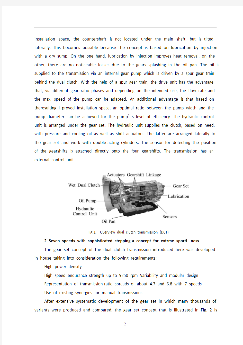
The 7-speed dual clutch transmission for the standard driveline presented here is designed for a torque capacity of up to 520 Nm and rotational speeds of up to 9250 rpms. In order to be able to achieve these performance data in the existing installation space, a concept was developed in which an oil chamber as well as lubrication by injection are used. Before introducing the transmission′s several unique features in more detail below, an overview of the basic transmission design will be presented, Fig. 1.The engine torque is introduced to the dual clutch via a torsion damper (not shown in Fig. 1). The multidisk clutches in the dual clutch are radially nested in one another and transfer the torque to both input shafts in the countershaft transmission gear set. In this case, due to the
installation space, the countershaft is not located under the main shaft, but is tilted laterally. This becomes possible because the concept is based on lubrication by injection with a dry sump. On the one hand, lubrication by injection improves heat removal, on the other, there are no noticeable losses due to the gears splashing in the oil pan. The oil is supplied to the transmission via an internal gear pump which is driven by a spur gear train behind the dual clutch. With the help of a spur gear train, the drive unit has the advantage that, via different gear ratio phases and depending on the intended use, the flow rate and the max. speed of the pump can be adapted. An additional advantage is that based on theresulting I proved installation space, an optimal ratio between the pump width and the pump diameter can be achieved for the pump′s level of efficiency. The hydraulic control unit is arranged under the gear set. The hydraulic unit supplies the clutch, based on need, with pressure and cooling oil as well as shift actuators. The latter are arranged laterally to the gear set and work with double-acting cylinders. The sensor for detecting the position of the gearshifts is attached directly onto the four gearshifts. The transmission has an external control unit.
Fig.1Overview dual clutch transmission (DCT)
2 Seven speeds with sophisticated stepping-a concept for extrme sporti- ness
The gear set concept of the dual clutch transmission introduced here was developed in house taking into consideration the following requirements:
High power density
High speed endurance strength up to 9250 rpm Variability and modular design
Representation of transmission-ratio spreads of about 4.7 and 6.8 with 7 speeds
Use of existing synergies for manual transmissions
After extensive systematic development of the gear set in which many thousands of variants were produced and compared, the gear set concept that is illustrated in Fig. 2 is
the final variant and the ideal concept for achieving the goals specified.
The gear set selected is based on the constant drive concept and consists of two concentric drive shafts each of which are driven by one of the two multidisk clutches in the
Fig.2Gear set scheme of 7D variant
dual clutch, two countershafts also concentric to one another, a main shaft and an output shaft. The gear ratios are engaged by the four synchronizer units A/B, C/D, E/F, and G/H, which are arranged on the main shaft and on the hollow countershaft and these are connected to the loose wheels or the adjacent shafts. An important feature in the gear set is the connectability of both countershafts through the C/D synchronizer unit. In the D shift position, the gear ratios selected in this way can be doubly used which reduces construction costs compared to conventional dual clutch gear sets. Similarly, this feature is used in first gear because then the vehicle is started up using the more powerful K1 clutch. Because of this dual use of the last gear level in the transmission for the first and second gear, the desired ratio step 1-2 is achieved through the transmission ratios of both constant drive phases.
The use of the K1 clutch for starting up in first gear results inevitably in the direct gear also being assigned to the odd subsection. In this case, the fifth and seventh gears can be selected as a direct drive. With this feature, it was possible to develop a modular gear set which, on just a few changes,contains two different transmission gear ratio variants with fundamentally different characters.
For the first version, with an overall spread of about 4 . 7 , the seventh gear is
selected as a direct gear (called the 7D variant). Fig. 2 shows the relevant gear set diagram with the performance flows in all speeds. Due to its sophisticated gear steps, this transmission is highly suitable for very sporty vehicles that need only a "little" transmission stepping due to the high rotating engine. Optimal tractive power can be provided at any time during vehicle operation.
The second version is based on the 7D variant, however, fifth gear was selected as the direct drive. When maintaining the torque multiplication ratio and in adapting the transmission ratio of several lower gear levels, you get the 5D variant with a considerably higher transmission-ratio spread for vehicles with increased comfort demands and simultaneously reduced consumption.
Fig. 3 illustrates the design of the 7D variant. The main similarity with existing manual transmissions for standard transmissions is noticeable. Due to the compact gear set design, the sufficient shaft dimensioning and the favorable arrangement in proximity of the bearing of the high transmitting ratios, central bearing glasses were not necessary despite the proportionally large bearing clearance.Overall, only two housing bearing levels are necessary where the front level is located behind both constant gears. In addition, a very compact and inexpensive transmission design could be implemented based on the bearing concept selected, especially in the area of the hollow shaft.
Fig.3Sectional Drawing of 7D variant
3 The dual clutch
The central module of this highly topical transmission concept is the wet dual clutch. With a broad spectrum of technical features, it implements the functional provisions of the transmission control unit and thus distinguishes the special character of this transmission concept.
Very fast delay times, low inertia and good, comfortable friction value progressions facilitate, very sporty handling with highly dynamic gear shifting and comfortable cruising
at a high level of efficiency. The dual clutch placed directly on the transmission input accepts the engine torque from thtorsion damper and feeds it to one of the two subsections, depending on the situation.
Safety considerations have led to a "normall open" design.
The radial arrangement of the multidisk pack age represents the best combination of performanc and installation space need, Fig. 4.
Fig.4Dual clutch
Careful lining and oil selection as well as intensive enhancement of this tribological system are the requirements for comfort and performance of this clutch throughout its service life.
Through intense testing and detailed calculations, it was possible to achieve a very high therma loading capacity. As part of the process, the lining type, dimensioning, and grooving as well as equal distribution of thermal load and oil flow in the multidisk package are decisive design features.
Low torque drag even with low temperatures as well as high speed endurance strength support comfort and a high level of sportiness, but are also important safety requirements.
Rotating, centrifugal force-compensating clutch cylinders with hysteresis optimized gaskets make the clutches easy to control. Integrated plate springs reliably accept rapid piston resetting even at high speeds.
In the case of an open clutch, only transmission input shafts with very low additional mass inertia are used. This supports rapid synchronizing sequences and a long service life of the synchronizer units.
4 The hydraulic control unit
In the present dual clutch transmission, the hydraulic control unit fulfills the following tasks:
Actuating the dual clutch
Shifting the gearshifts, i. e. engaging/synchronizing the gear
Cooling the dual clutch
Gear lubrication
Emergency stop function in case of complete failure of transmission electronics
Several features in the hydraulic control unit as well as criteria for the selection of the control concept are going to be described in more detail below.
4.1 Performance
The use of the dual clutch transmission in sporty vehicles demands high performance from the hydraulic control unit, especially with regard to the first two tasks because the timely "handling" of these tasks come into play in gear shifting and gear shifting times.
That is why particular value is placed on the selection of the right control unit concept as part of the system design. During the decision process, the choice was made, in principle, between two concepts, Fig. 5.
Fig.5Control concept direct control / precontrol
Precontrol of the valves
Direct control of the valves (so-called cartridge valves)
In case of direct control, the valve that is used for pressure control, e.g. a clutch, is directly connected to the power-generating proportional solenoids and provides the main pressure to the corresponding clutch pressure.
The precontrol uses the pressure that is supplied by a pressure controller, for example,
to actuate an additional valve that supplies the clutch pressure from the main pressure.
To assess the performance of both concepts, a larger number of compared measurements were performed with different systems, of which two systems shall be considered here:
ZF hydraulic control unit with precontrol for DCT standard drive
Comparative hydraulic control unit with direct control
A reference clutch was used as the clutch to engage. Criteria for assessing the performance were (see also Fig. 6):
Fig.6Delay, increase/rise, and fall times. Red curve: Power /Electric current. Green curve: Clutch
pressure
Delay time, 1 to 4
Time of step response until clutch inflation pressure, 1 to 2
Time of the step response up to 90% of the main pressure 1 to 3
Time of pressure drop (emptying times), 5 to 6
Fig. 6 shows, as an example, the times for a transmission oil temperature of + 20°C to be reached. One notices that the direct control first in dicates a lower delay time (14.3 ms) compared to the precontrol (30.1 ms), see also time of brand 1to 4.
For increase to clutch inflation pressure or to 90% of the main pressure shows, however, the advantage of the precontrolled system (see also summarizing tab 1).
Emptying times, also present a disadvantage for direct control. Trans-mission oil
temperature of -20°C also show comparable results for step responses and fall times.
All of the tests support the statement that direct control has an advantageous effect with small oil volumes. However, if large oil volumes have to be transported, precontrol valves are to be preferred due to larger opening cross-sections.
4.2 Operational safety
Operational safety is determined essentially due to the soiling tendency because the so-called silting can lead to the valves getting jammed. Provocation tests with transmission-specific environmental conditions (dirty oil) demonstrated the influences of soiling on the characteristic curves. Technical, trouble-free characteristic curve progressions could be illustrated only with a high dither amplitude in valve actuation, which leads, in turn, to increased valve wear-and-tear due to the micro movements that it causes. The increased tendency toward soiling can result needing a fine filter.
4.3 Costs
In addition to the delay time comparison as well as assessing the operational safety, the costs were relevant for a final evaluation. The compari son with regard to the hydraulic and electro-mag netic components shows that a precontrol system has cost benefits compared to a direct control system. Added to this are the higher flows with the actuation of direct control valves, which, in turn, result in a more expensive TCU. Furthermore, in opting for precontrol, ZF is able to "pool" together pressure controllers in large quantities because these, too, are used in the automatic ZF planetary gear set.
4.4 Emergency stop function
In case there is a complete outage in the transmission electronics, a hydraulic emergency stop function is actuated in the transmission. The clutch that is pressurized with a larger amount of pressure in the event of a system outage will continue to be pressurized. This condition is maintained until an adjustable engine speed threshold is achieved, then the clutch opens in order to prevent the engine from being choked. It is not possible to re-start this system.
5 Sporty functions
For function developers, the dual clutch transmission offers the opportunity to combine the comfort of a stepped automatic transmission with the dynamics and sportiness of a countershaft transmission. Connected, therefore, are typical " catalog values," such as time from zero to 100 kilometers per hour or the time from 80 to 120
kilometers per hour with correspondingly fast kick-down shifting, but also subjective acceleration sensitivity during a shifting sequence where the purist among the manual transmission drivers still wants to feel that jolt of acceleration.
One function especially designed for the dual clutch transmission in sports cars is the "race start"function. The race start is a function used to achieve optimal acceleration from a standstill, i.e. in the shortest time from 0 to 100 km/h. The sequence progresses as follows:
The engine is brought to a suitably high rpm with the clutch engaged in first gear. The driver simultaneously actuates the brakes with the lef foot so that the clutch can already be lightly engaged and the gas pedal (full throttle) in order to bring the vehicle up to the target speed. By simultaneously pressing and holding an operating element, such as the selector lever or a push button on the steering wheel, the race start intention is conveyed to the system, the engine speed adjusted and the start up prevented until the driver releases the brake. During the race start, the clutch is closed under the control of the wheel slip with which the optimal acceleration is achieved and by exploiting the dynamic engine torque (inertia torque). The entire procedure progresses automatically once the driver releases so that even an inexperienced driver
can achieve the best possible drive performance figures. Obviously, the driver can cancel the procedure by removing his/her foot from the gas pedal or touching the brakes. Also, the system recognizes when the street conditions do not permit a race start, such as wet roads, for example. Due to the optimal start-up and a shifting sequence into second gear free of traction interruption (see also sports shifting), the race start function enables the acceleration time of 0 to 100 km/h to be improved by an average of 0.2 sec compared to a car with a manual transmission. At the same time, this functionality helps avoid improper use and resulting clutch overload.
The top chart in Fig. 7 illustrates the engine and transmission input shaft speed, the lower chart shows the vehicle′s longitudinal acceleration. Starting with a cranking speed of 6,800 rpm, the clutch begins to close, which leads to an engine pressure up to about 4,000 rpm. The dynamic engine torque used to achieve this results in an acceleration of 0.7-0.9 g. In the process, noticeable vibrations in the transmission input shaft speed signal develop due to the wheel slip regulation. After about 1.2 sec, the vehicle is accelerated only by the engine torque with approx. 0.5 g. It must be mentioned here that this test was
performed using a vehicle with very high traction. In most cases, a starting speed of only up to about 4,000 rpm is reasonable.
A further function developed for the dual clutch transmission is so-called sports shifting. This is described in more detail below.
In general, a gear-shift change by the driver is only perceived acoustically by the change in the engine speed. The transition from the acceleration level of the original gear to
Fig.7Measurement of a race star
the new gear should be made smoothly and continuously. This also corresponds to the standard shifting sequences in auto-matic and dual clutch transmissions. However, many drivers of sporty cars wish that they had the option of both distinctive comfort shifting sequences as well as sporty shifting sequences, which, besides the haptic response (acceleration jolt), also have an acceleration advantage as a result. To this end, the dynamic engine torque can also be used again. The requirement for this is the torque capacity of the dual clutch which has to be able to transmit this torque increase. As the possible torque increase depends on the gradients of the engine speed, this can be used particularly effectively in shifting gears with a large speed difference with the target gear (large ratio spread/ratio step), which is why the gear changes 1-2, 2-3, and 3-4 are offered. In the process, sports shifting from the frst to second gear can serve as a supplement to the ace start for improving the acceleration time from to 100 km/h. As the use of the
dynamic torque is pure application topic, we distinguish, as a rule,between three shifting systems. Fig. 8 illustrates he stylized differences and features between the hifting systems, Fig. 9 shows an original measurement from a prototype vehicle.
The top chart shows the respective engine and ransmission speed, the bottom chart shows the orques from both clutches. The bottom line in the hart represents the clutch from the target gear that is used to achieve the torque increase during engine sp eed adjustment and thereby acceleration gains.
Fig.8Simplified depiction of acceleration procedures with
Fig.9Measurement of sports shift 2-3 in the vehicle
附录B外文文献翻译
运动型7速双离合器变速器系统
摘要:ZF公司的7速双离合器变速器是一款创新型的、适用于运动型车辆的变速器。精密的速比和自然拥有的极佳驾驶性能使得它成为运动型车辆理想的变速装置。本文对该变速器紧凑的齿轮机构、可改善效率和提高发动机-速度-强度的直接喷射润滑系统,双离合器系统及基于预先控制原理的液压控制单元等作了详细介绍。在出现电气故障时液压控制系统可选用液压巡航模式。另外,变速器设计、功能特性等也都体现出变速器具有鲜明的运动特征。
关键词:自动变速器;双离合器;车辆连接;效率
1.前言
提及自动变速器时,双离合器系统被普遍认为是运动型的标杆。基于中间轴结构的该类变速器的优点是非常直接的“车辆连接”、高转速性能和及其优越的变速器效率。
本文介绍的用于标准型传动系统的7速双离合器变速器的最大转矩可达520 Nm、最高转速为9250 rpm。为在现有安装空间内实现这些性能数据,创造性的引入了储油室和润滑油直接喷射概念。在详细介绍变速器各特点之前,首先对变速器给出一个总的描述,见图1。
图1双离合器变速器(DCT)剖视图
发动机转矩经过扭转减振器(未在图1中表示)传递给双离合器。双离合器中的多片式离合器沿径向互相嵌套并将转矩通过两输入轴传递给中间轴齿轮装置。这里,因为安装空间的缘故,中间轴并不位于主轴下方,而是横向斜置。用于采用了带干油箱的直接喷射润滑,才有这样的可能。一方面,直接喷射改善了热传递,另一方面不会在油底壳中出现明显的飞溅损失。向变速器供给的润滑油由内啮合齿轮泵提供,利用齿轮机构驱动的该泵安装在双离合器后面。借助于该齿轮机构,驱动装置的优点是可根据不同的齿轮速比和预期的需要获得适合的流速和油泵最高转速。另一优点是改善了安装空间,可根据油泵效率实现油泵宽度和直径之间的最佳比例。液压控制单元安装在齿轮机构的下方。液压控制单元根据需要向离合器和换档执行机构提供压力和冷却润滑油。而采用双向作用油缸的换档执行机构则安装在齿轮机构的侧面。检测档位位置的传感器直接安装在四根换档轴上。变速器具有一个外部控制单元。
2.七个精密档位-极具运动性的概念
这里引入的双离合器变速器齿轮机构考虑了以下需求:
高动力密度;
高达9250 rpm的高速耐久强度;
可变性和模块化设计;
变速特性-速比范围从4.7到6.8;
源于现有的手动变速器。
据此对齿轮机构进行了广泛的系统开发,引入并比较了数以千计的变量,图2所示的齿轮机构是最终形式,是一个满足各项目标的理想概念。
所选择的齿轮机构是基于常规传动概念,变速器由各由双离合器中的一组多片式离合器驱动的两根同心传动轴、两根同心的副轴、主轴和输出轴组成。齿轮速比的变化由4组同步器A/B、C/D、E/F和G/H实现,这些同步器布置在主轴和中空的中间轴
上并连接到自由轮或相邻轴上。
齿轮机构的一个主要特征是两中间轴通过C/D同步器连接。在D位置可两次选择齿轮速比,与常规双离合器变速器相比降低了成本。同样,该特征也被应用在1档齿轮上,因此当车辆起步时可利用更强有力的K1离合器。由于变速器1档和2档均使用了最后一对齿轮,1-2档之间的速比是由两常啮合齿轮副确定。
利用K1离合器和1档起步不可避免的会导致直接档齿轮设定成奇数。这时,5档和7档齿轮可选作直接档传动。据此可开发一模块化齿轮机构,仅需少量改变而获得两种具有不同特性的齿轮速比。
第一种结构的总速比是4.7,7档齿轮作为直接档(称为7D型)。图2给出了齿轮机构的动力流。借助于精密的速比间隔,该变速器非常适用于高发动机转速和“小”速比间隔的运动型车辆。可在车辆的各种工况下获得最佳的牵引力。
第二种结构基于7D型,但将5档作为直接档。当维持转矩放大倍数和稍稍减少变速器档位数时, 5D型仍具有相当高的变速器总速比范围并且提高了舒适性同时也降
图27D型齿轮机构简图
低了油耗。
图3是7D变速器的设计图。和现有标准的手动变速器的相似之处是显见的。由于齿轮机构设计紧凑,各轴具有足够的尺寸并且有利于在大速比处布置轴承,中央轴承罩无需顾及大的轴承间隙。由于前轴承座位于两常啮合齿轮后部,因此仅需两个轴承座即可。另外,非常紧凑和廉价的变速器设计也是基于对轴承的选择,特别在空心轴方面。
图37D型变速器剖面图
3.双离合器
该变速器的核心模块是湿式双离合器。该离合器具有一个宽型谱的技术特征,能实现变速器控制单元的功能和辨别该变速器的专有特征。
离合器延迟时间短、惯量小、动作过程中具有良好和舒适的摩擦系数、极具运动性的高动态换档特性、行驶舒适以及高效率。
双离合器直接安装在变速器的输入端,发动机转矩经扭转减振器后根据具体情况传递给两离合器中的任一个。出于安全考虑,离合器设计成“常开”状态。
沿径向布置的多片离合器具有最佳的性能和安装空间,见图4。
图4双离合器
确保离合器在使用寿命中其性能和舒适性取决于摩擦片衬里、润滑油的选择和提高该摩擦学系统的性能。
经过大量试验和详细计算,获得了相当高的热负载特性。作为其中的一部分,摩擦片衬里的类型、尺寸、沟槽以及在离合器壳体中热负荷耗散和润滑油流动等都是决定性的设计特点。
离合器甚至在低温情况下也具有低的牵引转矩,并具有高速疲劳强度、运动舒适性和高水平的运动性,同时也能满足安全性方面需要。
装有滞后优化垫圈和配备有离心力补偿的离合器主缸使得离合器操控更容易。板簧能确保高速时活塞的快速回位。
在离合器断开情况下,变速器输入轴仅有非常低的附加转动惯量。这样可确保快速同步和同步器的长寿命。
4.液压控制单元
在现有的双离合器变速器中,液压控制单元应完成下列任务:
操纵双离合器;
换档,即齿轮的结合/同步;
冷却双离合器;
变速器电子系统完全失效时的应急停车功能;
液压控制单元的几个特征和控制概念的选择标准详见以下各小节。
(1)性能
在运动型车辆上使用双离合器需要有高性能的液压控制单元,特别是在实现第一和第二项任务时,因为这些任务的及时处理关系到换档和换档时间。
这就是为什么作为系统设计一部分的正确选择控制单元概念的重要性。在做决策时,所做的选择在原则上主要介于预先控制阀和直接控制阀(又称为模块阀)两概念之间,见图5。
图5直接控制/预先控制概念
如果采用直接控制,阀门采用压力控制即离合器直接与产生动力的比例电磁线圈连接并提供主压力至相应的离合器压力。
预先控制采用的压力由压力控制器提供例如利用一个附加的阀门从主压力处提供离合器压力。
为评价两概念的性能,用不同系统进行了大量的对比测试,以下内容是两系统必须被考虑到的:
ZF标准的DCT液压控制单元采用预先控制与直接控制相比
用一个参考离合器进行结合试验。性能评定标准是(见图6):
延迟时间,1-4;
离合器充满压力的瞬态响应时间,1-2;
达到90%主压力的瞬态响应时间,1-3;
压力下降时间(排空时间),5-6。
图6是一个实例,给出了变速器润滑油温度为+20°C时所实现的时间。有一点需注意的是直接控制首先表现出具有较短的延迟时间(14.3 ms)而预先控制需30.1 ms,见标号1-4。
直接控制的排空时间也占优。当变速器润滑油温度为-20°C时的对比结果也显示瞬态响应和排空时间更优。
所有试验都表明直接控制效率高、润滑油流量小。然而,如果必须大流量输送润滑油的话,预先控制阀由于具有更大的横截面通道将是首选。
(2)使用可靠性
使用可靠性主要是由于污染所致,因为淤积会使得阀门堵塞。变速器在特定环境下(脏润滑油)的诱发试验表明污染会对特性曲线有影响。从技术上看,无故障的阀门特性
图6延迟、增加和排空时间。红色曲线:动力/电流。绿色曲线:离合器压力
曲线仅在高频振幅时才能实现,但高频振动产生的微动将增加阀门的磨损。污染趋势增加的后果是需要一精滤器。
(3)成本
除了延迟时间对比和使用可靠性评定外,成本对最终评价有着重大意义。对液压和
电磁元件的比较表明预先控制系统比直接控制系统在成本方面占优。直接控制阀门动作时增加的流量导致TCU更昂贵。而且,在选择预先控制时,ZF公司能大量采购压力控制器,因为它们也被应用在ZF自动变速器的行星齿轮机构上。
(4)应急停车功能
万一变速器电子元件完全断电,液压应急停车功能将作用于变速器。如果发生系统断电时离合器将获得一个更大的压力以维持受压状态。该状态一直维持到获得一个可调整的发动机速度阈值为止,然后离合器脱开以避免发动机节气门阻塞。这时不可能重启该系统。
5.运动性功能
对于功能开发,双离合器变速器提供了有级自动变速器的动态舒适性和中间轴式变速器的运动性。因此与之相关联的典型“目录数值”是诸如0到100 km/h加速时间或80到120 km/h使用快速kick-down换档的加速时间,以及在顺序换档过程中对加速敏感性的主观评价,包括纯正的手动变速器驾驶员所要求的加速摇晃感觉等。
运动型轿车双离合器变速器设计中的一项特殊功能是“起跑”功能。起跑功能被用来实现从静态开始的最佳加速,即在最短的时间完成从0-100km/h加速。整个过程如下:
发动机提供一个适当的高转速用于离合器结合1档。驾驶员同时用左脚踩住制动踏板,这时离合器已经稍稍结合然后踩下加速踏板(全节气门)直到车辆达到目标速度。与此同时按住一操纵元件,如选档杆或转向盘上的按钮,起跑的意图被传递到系统中,直到驾驶员松开制动之前发动机转速被调节但起动仍被禁止。在起跑过程中,离合器的结合受控于车轮的滑移率,以获得最佳的加速度和充分利用动态发动机转矩(惯性矩)。一旦驾驶员松开制动整个过程自动完成,所以即便是一个不熟练的驾驶员也能进行最佳的驾驶表演。显然,当驾驶员松开加速踏板或踩制动踏板时可取消该过程。
同样,当道路情况不允许起跑时,如道路湿滑,系统能够确认之。由于最佳起步和在无动力中断的情况下顺序换入2档,起跑功能使得0-100 km/h加速时间比手动变速器减少0.2 s。同时,该功能有助于避免使用不当以导致离合器超载。
图7上部的图表示发动机和变速器输入轴转速,下部的图表示车辆纵向加速度。起步时曲轴转速为6800 rpm,离合器开始结合,导致发动机转速降至4000 rpm。动态发动机转矩所产生的结果是0.7-0.9 g的加速度。在该进程中,由于车轮滑变速器输入轴转速信号处出现明显的振动。约1.2 s后,车辆仅由发动机转矩加速,加速度约为0.5 g。这里必须提及的是试验中使用的车辆具有非常高的牵引力。在大多数情况下,起步转速最高约为4000 rpm。
图7起跑实测
运动性换档是对双离合器变速器功能的进一步开发。以下作详细论述。通常,驾驶员是听到发动机转速改变而感觉到档位变化。变速器的加速度从原档位到新档位应该平滑而连续。这就是自动变速器和双离合器变速器的标准换档程序。但是许多运动型轿车的驾驶员希望可在舒适性换档和运动性换档程序之间做选择,即除了感觉(加速度冲击)上不同之外,还希望加速更快。最终,动态发动机转矩被再次使用。为此,要求双离合器的转矩容量必须能传递该增加的转矩。因为可能的转矩增加量取决于发动机转速梯度,这将被特别有效地应用在具有大速度差的档位之间(大速比范围/速比间隔),即在1-2、2-3和3-4档时应用。在此过程中,从1档到2档的运动型换档可作为起跑的补充以改善0-100km/h加速时间。因为动态转矩的应用是一个纯粹的应用话题,通常,我们将3种换档系统加以区分。
图8是各种换档系统的差别和特征,图9则是原型车的实测数据。图的上部是发动机和变速器的转速,下部是两离合器的转矩。图中下面的曲线反应了在给定档位下和发动机转速调节期间离合器所获得的增加转矩及由此产生的加速效果。
图8不同换档系统加速过程的简单描述
图9运动性2-3档换档时车辆的测量值
中英文对照外文翻译 汽车变速器设计 我们知道,汽车发动机在一定的转速下能够达到最好的状态,此时发出的功率比较大,燃油经济性也比较好。因此,我们希望发动机总是在最好的状态下工作。但是,汽车在使用的时候需要有不同的速度,这样就产生了矛盾。这个矛盾要通过变速器来解决。 汽车变速器的作用用一句话概括,就叫做变速变扭,即增速减扭或减速增扭。为什么减速可以增扭,而增速又要减扭呢?设发动机输出的功率不变,功率可以表示为 N = w T,其中w是转动的角速度,T 是扭距。当N固定的时候,w与T是成反比的。所以增速必减扭,减速必增扭。汽车变速器齿轮传动就根据变速变扭的原理,分成各个档位对应不同的传动比,以适应不同的运行状况。 一般的手动变速器内设置输入轴、中间轴和输出轴,又称三轴式,另外还有倒档轴。三轴式是变速器的主体结构,输入轴的转速也就是发动机的转速,输出轴转速则是中间轴与输出轴之间不同齿轮啮合所产生的转速。不同的齿轮啮合就有不同的传动比,也就有了不同的转速。例如郑州日产ZN6481W2G型SUV车手动变速器,它的传动比分别是:1档3.704:1;2档2.202:1;3档1.414:1;4档1:1;5档(超速档)0.802:1。 当汽车启动司机选择1档时,拨叉将1/2档同步器向后接合1档
齿轮并将它锁定输出轴上,动力经输入轴、中间轴和输出轴上的1档齿轮,1档齿轮带动输出轴,输出轴将动力传递到传动轴上(红色箭头)。典型1档变速齿轮传动比是3:1,也就是说输入轴转3圈,输出轴转1圈。 当汽车增速司机选择2档时,拨叉将1/2档同步器与1档分离后接合2档齿轮并锁定输出轴上,动力传递路线相似,所不同的是输出轴上的1档齿轮换成2档齿轮带动输出轴。典型2档变速齿轮传动比是2.2:1,输入轴转2.2圈,输出轴转1圈,比1档转速增加,扭矩降低。 当汽车加油增速司机选择3档时,拨叉使1/2档同步器回到空档位置,又使3/4档同步器移动直至将3档齿轮锁定在输出轴上,使动力可以从轴入轴—中间轴—输出轴上的3档变速齿轮,通过3档变速齿轮带动输出轴。典型3档传动比是1.7:1,输入轴转1.7圈,输出轴转1圈,是进一步的增速。 当汽车加油增速司机选择4档时,拨叉将3/4档同步器脱离3档齿轮直接与输入轴主动齿轮接合,动力直接从输入轴传递到输出轴,此时传动比1:1,即输出轴与输入轴转速一样。由于动力不经中间轴,又称直接档,该档传动比的传动效率最高。汽车多数运行时间都用直接档以达到最好的燃油经济性。 换档时要先进入空档,变速器处于空档时变速齿轮没有锁定在输出轴上,它们不能带动输出轴转动,没有动力输出。 一般汽车手动变速器传动比主要分上述1-4档,通常设计者首先确定最低(1档)与最高(4档)传动比后,中间各档传动比一
前言 在目前激烈的市场竞争中,产品投入市场的迟早往往是成败的关键。模具是高质量、高效率的产品生产工具,模具开发周期占整个产品开发周期的主要部分。因此客户对模具开发周期要求越来越短,不少客户把模具的交货期放在第一位置,然后才是质量和价格。因此,如何在保证质量、控制成本的前提下加工模具是值得认真考虑的问题。模具加工工艺是一项先进的制造工艺,已成为重要发展方向,在航空航天、汽车、机械等各行业得到越来越广泛的应用。模具加工技术,可以提高制造业的综合效益和竞争力。研究和建立模具工艺数据库,为生产企业提供迫切需要的高速切削加工数据,对推广高速切削加工技术具有非常重要的意义。本文的主要目标就是构建一个冲压模具工艺过程,将模具制造企业在实际生产中结合刀具、工件、机床与企业自身的实际情况积累得高速切削加工实例、工艺参数和经验等数据有选择地存储到高速切削数据库中,不但可以节省大量的人力、物力、财力,而且可以指导高速加工生产实践,达到提高加工效率,降低刀具费用,获得更高的经济效益。 1.冲压的概念、特点及应用 冲压是利用安装在冲压设备(主要是压力机)上的模具对材料施加压力,使其产生分离或塑性变形,从而获得所需零件(俗称冲压或冲压件)的一种压力加工方法。冲压通常是在常温下对材料进行冷变形加工,且主要采用板料来加工成所需零件,所以也叫冷冲压或板料冲压。冲压是材料压力加工或塑性加工的主要方法之一,隶属于材料成型工程术。 冲压所使用的模具称为冲压模具,简称冲模。冲模是将材料(金属或非金属)批量加工成所需冲件的专用工具。冲模在冲压中至关重要,没有符合要求的冲模,批量冲压生产就难以进行;没有先进的冲模,先进的冲压工艺就无法实现。冲压工艺与模具、冲压设备和冲压材料构成冲压加工的三要素,只有它们相互结合才能得出冲压件。 与机械加工及塑性加工的其它方法相比,冲压加工无论在技术方面还是经济方面都具有许多独特的优点,主要表现如下; (1) 冲压加工的生产效率高,且操作方便,易于实现机械化与自动化。这是
附录一英文科技文献翻译 英文原文: Experimental investigation of laser surface textured parallel thrust bearings Performance enhancements by laser surface texturing (LST) of parallel-thrust bearings is experimentally investigated. Test results are compared with a theoretical model and good correlation is found over the relevant operating conditions. A compari- son of the performance of unidirectional and bi-directional partial-LST bearings with that of a baseline, untextured bearing is presented showing the bene?ts of LST in terms of increased clearance and reduced friction. KEY WORDS: ?uid ?lm bearings, slider bearings, surface texturing 1. Introduction The classical theory of hydrodynamic lubrication yields linear (Couette) velocity distribution with zero pressure gradients between smooth parallel surfaces under steady-state sliding. This results in an unstable hydrodynamic ?lm that would collapse under any external force acting normal to the surfaces. However, experience shows that stable lubricating ?lms can develop between parallel sliding surfaces, generally because of some mechanism that relaxes one or more of the assumptions of the classical theory. A stable ?uid ?lm with su?cient load-carrying capacity in parallel sliding surfaces can be obtained, for example, with macro or micro surface structure of di?erent types. These include waviness [1] and protruding microasperities [2–4]. A good literature review on the subject can be found in Ref. [5]. More recently, laser surface texturing (LST) [6–8], as well as inlet roughening by longitudinal or transverse grooves [9] were suggested to provide load capacity in parallel sliding. The inlet roughness concept of Tonder [9] is based on ??e?ective clearance‘‘ reduction in the sliding direction and in this respect it is identical to the par- tial-LST concept described in ref. [10] for generating hydrostatic e?ect in high-pressure mechanical seals. Very recently Wang et al. [11] demonstrated experimentally a doubling of the load-carrying capacity for the surface- texture design by reactive ion etching of SiC
附录 附录A. Manual Transmission It’s no secret that cars with manual transmissions are usually more fun to drive than the automatic-equipped counterparts. If you have even a passing interest in the act of driving, then chances are you also appreciate a fine-shifting manual gearbox. But how does a manual transmission actually work? A history hows that manual transmissions preceded automatics by several decades. In fact,up until General Motors offered an automatic in 1938, all cars were of the shift-it-yourself variety. While it’s logical for many types of today’s vehicles to be equipped with an automatic――such as a full-size sedan, SUV or pickup――the fact remains that nothing is more of a thrill to drive than a tautly suspended sport sedan, snort coupe or two-sealer equipped with a precise-shifting five-or six-speed gearbox. We know whicn types or cars have manual trannies. Now let’s take a look at how they work. From the most basic four-speed manual in a car from the’60s to the most high-tech six-speed one in a car of today, the principles of a manual gearbox are the same. The driver must shift from gear to gear. Normally, a manual transmission bolts to a clutch housing (or bell housing), in turn, bolts to the back of the engine. If the vehicle has front-wheel drive,
机械设计理论 机械设计是一门通过设计新产品或者改进老产品来满足人类需求的应用技术科学。它涉及工程技术的各个领域,主要研究产品的尺寸、形状和详细结构的基本构思,还要研究产品在制造、销售和使用等方面的问题。 进行各种机械设计工作的人员通常被称为设计人员或者机械设计工程师。机械设计是一项创造性的工作。设计工程师不仅在工作上要有创造性,还必须在机械制图、运动学、工程材料、材料力学和机械制造工艺学等方面具有深厚的基础知识。如前所诉,机械设计的目的是生产能够满足人类需求的产品。发明、发现和科技知识本身并不一定能给人类带来好处,只有当它们被应用在产品上才能产生效益。因而,应该认识到在一个特定的产品进行设计之前,必须先确定人们是否需要这种产品。 应当把机械设计看成是机械设计人员运用创造性的才能进行产品设计、系统分析和制定产品的制造工艺学的一个良机。掌握工程基础知识要比熟记一些数据和公式更为重要。仅仅使用数据和公式是不足以在一个好的设计中做出所需的全部决定的。另一方面,应该认真精确的进行所有运算。例如,即使将一个小数点的位置放错,也会使正确的设计变成错误的。 一个好的设计人员应该勇于提出新的想法,而且愿意承担一定的风险,当新的方法不适用时,就使用原来的方法。因此,设计人员必须要有耐心,因为所花费的时间和努力并不能保证带来成功。一个全新的设计,要求屏弃许多陈旧的,为人们所熟知的方法。由于许多人墨守成规,这样做并不是一件容易的事。一位机械设计师应该不断地探索改进现有的产品的方法,在此过程中应该认真选择原有的、经过验证的设计原理,将其与未经过验证的新观念结合起来。 新设计本身会有许多缺陷和未能预料的问题发生,只有当这些缺陷和问题被解决之后,才能体现出新产品的优越性。因此,一个性能优越的产品诞生的同时,也伴随着较高的风险。应该强调的是,如果设计本身不要求采用全新的方法,就没有必要仅仅为了变革的目的而采用新方法。 在设计的初始阶段,应该允许设计人员充分发挥创造性,不受各种约束。即使产生了许多不切实际的想法,也会在设计的早期,即绘制图纸之前被改正掉。只有这样,才不致于堵塞创新的思路。通常,要提出几套设计方案,然后加以比较。很有可能在最后选定的方案中,采用了某些未被接受的方案中的一些想法。
The development of automobile As the world energy crisis and the war and the energy consumption of oil -- and are full of energy in one day someday it will disappear without a trace. Oil is not inresources. So in oil consumption must be clean before finding a replacement. With the development of science and technology the progress of the society people invented the electric car. Electric cars will become the most ideal of transportation. In the development of world each aspect is fruitful especially with the automobile electronic technology and computer and rapid development of the information age. The electronic control technology in the car on a wide range of applications the application of the electronic device cars and electronic technology not only to improve and enhance the quality and the traditional automobile electrical performance but also improve the automobile fuel economy performance reliability and emission spurification. Widely used in automobile electronic products not only reduces the cost and reduce the complexity of the maintenance. From the fuel injection engine ignition devices air control and emission control and fault diagnosis to the body auxiliary devices are generally used in electronic control technology auto development mainly electromechanical integration. Widely used in automotive electronic control ignition system mainly electronic control fuel injection system electronic control ignition system electronic control automatic transmission electronic control ABS/ASR control system electronic control suspension system electronic control power steering system vehicle dynamic control system the airbag systems active belt system electronic control system and the automatic air-conditioning and GPS navigation system etc. With the system response the use function of quick car high reliability guarantees of engine power and reduce fuel consumption and emission regulations meet standards. The car is essential to modern traffic tools. And electric cars bring us infinite joy will give us the physical and mental relaxation. Take for example automatic transmission in road can not on the clutch can achieve automatic shift and engine flameout not so effective improve the driving convenience lighten the fatigue strength. Automatic transmission consists mainly of hydraulic torque converter gear transmission pump hydraulic control system electronic control system and oil cooling system etc. The electronic control of suspension is mainly used to cushion the impact of the body and the road to reduce vibration that car getting smooth-going and stability. When the vehicle in the car when the road uneven road can according to automatically adjust the height. When the car ratio of height low set to gas or oil cylinder filling or oil. If is opposite gas or diarrhea. To ensure and improve the level of driving cars driving stability. Variable force power steering system can significantly change the driver for the work efficiency and the state so widely used in electric cars. VDC to vehicle performance has important function it can according to the need of active braking to change the wheels of the car car motions of state and optimum control performance and increased automobile adhesion controlling and stability. Besides these appear beyond 4WS 4WD electric cars can greatly improve the performance of the value and ascending simultaneously. ABS braking distance is reduced and can keep turning skills effectively improve the stability of the directions simultaneously reduce tyre wear. The airbag appear in large programs protected the driver and passengers safety and greatly reduce automobile in collision of drivers and passengers in the buffer to protect the safety of life. Intelligent electronic technology in the bus to promote safe driving and that the other functions. The realization of automatic driving through various sensors. Except some smart cars equipped with multiple outside sensors can fully perception of information and traffic facilities
本科毕业论文(设计) 外文翻译 学院:机电工程学院 专业:机械工程及自动化 姓名:高峰 指导教师:李延胜 2011年05 月10日 教育部办公厅 Failure Analysis,Dimensional Determination And
Analysis,Applications Of Cams INTRODUCTION It is absolutely essential that a design engineer know how and why parts fail so that reliable machines that require minimum maintenance can be designed.Sometimes a failure can be serious,such as when a tire blows out on an automobile traveling at high speed.On the other hand,a failure may be no more than a nuisance.An example is the loosening of the radiator hose in an automobile cooling system.The consequence of this latter failure is usually the loss of some radiator coolant,a condition that is readily detected and corrected.The type of load a part absorbs is just as significant as the magnitude.Generally speaking,dynamic loads with direction reversals cause greater difficulty than static loads,and therefore,fatigue strength must be considered.Another concern is whether the material is ductile or brittle.For example,brittle materials are considered to be unacceptable where fatigue is involved. Many people mistakingly interpret the word failure to mean the actual breakage of a part.However,a design engineer must consider a broader understanding of what appreciable deformation occurs.A ductile material,however will deform a large amount prior to rupture.Excessive deformation,without fracture,may cause a machine to fail because the deformed part interferes with a moving second part.Therefore,a part fails(even if it has not physically broken)whenever it no longer fulfills its required function.Sometimes failure may be due to abnormal friction or vibration between two mating parts.Failure also may be due to a phenomenon called creep,which is the plastic flow of a material under load at elevated temperatures.In addition,the actual shape of a part may be responsible for failure.For example,stress concentrations due to sudden changes in contour must be taken into account.Evaluation of stress considerations is especially important when there are dynamic loads with direction reversals and the material is not very ductile. In general,the design engineer must consider all possible modes of failure,which include the following. ——Stress ——Deformation ——Wear ——Corrosion ——Vibration ——Environmental damage ——Loosening of fastening devices
外文翻译 文章出处《Tribology International》, 2009, 42(5):714-723 译文: 有限元热分析的陶瓷离合器 1 引言 磨料空转车辆离合器是力封闭联轴器。扭矩和高速传输被压紧表面之间产生的摩擦力所保证。应用陶瓷是因为它作为摩擦介质具有好耐热和耐磨损性能,提供了机会以驱动更高的压力,以及一个低的密度。因此,一个提功率密度启用了一个平行的最小化建筑空间。 测量使用陶瓷饰面离合器盘的第一个原型在卡尔斯鲁厄大学的一个实验室专门从事客车驱动系统进行了测试执行。在分析过程中的有限元(FE)模型是将与测量数据和测量条件的知识所构成。计算的目的是要确定在离合器盘上温度的分布以及环境中的在每一时刻的及时测量目。至关重要的是熟悉的温度范围,为了检验该系统的耐磨特性。因此,重要信息从测量数据中得出。在临界负载的情况下,预计最高温度必须在时间和空间上进行预测,为保护接近发热体的位置测量工具的。 本研究的目的是分析和修改该离合器系统通过改进,以提供更好的工作条件热传导和系统或增加转化成摩擦热的能量的对流。此外,人们希望找到更有效的更好的离合器系统设计方案。 计算是由宇宙星空的设计的软件进行的。在模型开发阶段,非常谨慎,必须采取几何元素,选择适当的简化尺寸,并且由于正确调整的时间步长大量的硬件要求瞬态计算。热物性参数的改变,如表面热对流化系数和热负荷,必须考虑到到在一个持续的基础上在时间和地点方面。离合器系统的分析测试这两方面,只能通过加热隔板连接的两个独立的模型来管理,根据该假说认为,接触温度必须是在两个相同的双方,同时他们要有适当接触,其价值需通过迭代来进行调整。计算显示,该热分区按周期变化,它沿不同的内,外接触环。在不同的冷却特性下,在陶瓷和钢之间的结果是不同的,热流从陶瓷侧面向钢侧流动。此热流也通过迭代确定;它的价值也改变了周期和不同沿着所述内和外接触环。 2 采用工程陶瓷作为摩擦材料的第一个原型机 这款检查过的离合器盘是根据“特定的陶瓷”产品而开发的,此材料的研发过程在流程在卡尔斯鲁厄大学的Institute for Product Development (IPEK)杂志上发表过。此开发过程已经具有的可能性,用于连接到一个真实的传动轴;甚至,它为面板有一个好的初始行为起到一个很好的缓冲作用。磨料配件必须符合以下基本要求:
机械类外文翻译 塑料注塑模具浇口优化 摘要:用单注塑模具浇口位置的优化方法,本文论述。该闸门优化设计的目的是最大限度地减少注塑件翘曲变形,翘曲,是因为对大多数注塑成型质量问题的关键,而这是受了很大的部分浇口位置。特征翘曲定义为最大位移的功能表面到表面的特征描述零件翘曲预测长度比。结合的优化与数值模拟技术,以找出最佳浇口位置,其中模拟armealing算法用于搜索最优。最后,通过实例讨论的文件,它可以得出结论,该方法是有效的。 注塑模具、浇口位臵、优化、特征翘曲变形关键词: 简介 塑料注射成型是一种广泛使用的,但非常复杂的生产的塑料产品,尤其是具有高生产的要求,严密性,以及大量的各种复杂形状的有效方法。质量ofinjection 成型零件是塑料材料,零件几何形状,模具结构和工艺条件的函数。注塑模具的一个最重要的部分主要是以下三个组件集:蛀牙,盖茨和亚军,和冷却系统。拉米夫定、Seow(2000)、金和拉米夫定(2002) 通过改变部分的尼斯达到平衡的腔壁厚度。在平衡型腔充填过程提供了一种均匀分布压力和透射电镜,可以极大地减少高温的翘曲变形的部分~但仅仅是腔平衡的一个重要影响因素的一部分。cially Espe,部分有其功能上的要求,其厚度通常不应该变化。 pointview注塑模具设计的重点是一门的大小和位臵,以及流道系统的大小和布局。大门的大小和转轮布局通常被认定为常量。相对而言,浇口位臵与水口大小布局也更加灵活,可以根据不同的零件的质量。 李和吉姆(姚开屏,1996a)称利用优化流道和尺寸来平衡多流道系统为multiple 注射系统。转轮平衡被形容为入口压力的差异为一多型腔模具用相同的蛀牙,也存
沈阳工业大学工程学院 毕业设计(论文)外文翻译 毕业设计(论文)题目:工具盒盖注塑模具设计 外文题目:Friction , Lubrication of Bearing 译文题目:轴承的摩擦与润滑 系(部):机械系 专业班级:机械设计制造及其自动化0801 学生姓名:王宝帅 指导教师:魏晓波 2010年10 月15 日
外文文献原文: Friction , Lubrication of Bearing In many of the problem thus far , the student has been asked to disregard or neglect friction . Actually , friction is present to some degree whenever two parts are in contact and move on each other. The term friction refers to the resistance of two or more parts to movement. Friction is harmful or valuable depending upon where it occurs. friction is necessary for fastening devices such as screws and rivets which depend upon friction to hold the fastener and the parts together. Belt drivers, brakes, and tires are additional applications where friction is necessary. The friction of moving parts in a machine is harmful because it reduces the mechanical advantage of the device. The heat produced by friction is lost energy because no work takes place. Also , greater power is required to overcome the increased friction. Heat is destructive in that it causes expansion. Expansion may cause a bearing or sliding surface to fit tighter. If a great enough pressure builds up because made from low temperature materials may melt. There are three types of friction which must be overcome in moving parts: (1)starting, (2)sliding, and(3)rolling. Starting friction is the friction between two solids that tend to resist movement. When two parts are at a state of rest, the surface irregularities of both parts tend to interlock and form a wedging action. To produce motion in these parts, the wedge-shaped peaks and valleys of the stationary surfaces must be made to slide out and over each other. The rougher the two surfaces, the greater is starting friction resulting from their movement . Since there is usually no fixed pattern between the peaks and valleys of two mating parts, the irregularities do not interlock once the parts are in motion but slide over each other. The friction of the two surfaces is known as sliding friction. As shown in figure ,starting friction is always greater than sliding friction . Rolling friction occurs when roller devces are subjected to tremendous stress which cause the parts to change shape or deform. Under these conditions, the material in front of a roller tends to pile up and forces the object to roll slightly uphill. This changing of shape , known as deformation, causes a movement of molecules. As a result ,heat is produced from the added energy required to keep the parts turning and overcome friction. The friction caused by the wedging action of surface irregularities can be overcome
外文翻译 Auto Transmission First, an overview of automotive transmission and the development trend Automobile available more than a century, especially from the mass production of motor vehicles and the automotive industry since the development of large, Car has been the economic development of the world for mankind to enter the modern life and have had a tremendous impact on the immeasurable, The progress of human society has made indelible contributions to the great, epoch-making set off arevolution. From From the vehicle as a power plant using internal combustion engine to start, auto transmission has become an important component. Is Generation is widely used in automotive reciprocating piston internal combustion engine with a small size, light weight, reliable operation and the use of The advantages of convenience, but its torque and speed range of smaller changes, and complex condition requires the use of motor vehicles Traction and the speed can be considerable changes in the scope. Therefore, its performance and vehicle dynamics and economy of There are large inter-contradictions, which contradictions of modern automotive internal combustion engine by itself is insoluble. Because Here, in the automotive power train set up the transmission and main reducer in order to achieve the purpose of deceleration by moment. Speed The main function of performance: ⑴ change gear ratio of motor vehicles, and expand the wheel drive torque and rotational speed of the Fan Wai, in order to adapt to constantly changing driving cycle, while the engine in the most favorable conditions within the scope of work; ⑵no change in the direction of engine rotation, under the premise of the realization of cars driving back; ⑶the realization of the free, temporary Interruption of power transmission, in order to be able to start the engine, idling, etc.. V ariable-speed drive transmission by the manipulation of institutions and agencies. Change the transmission ratio by way of transmission is divided into There are class-type, non-stage and multi-purpose three. Have class most widely used transmission. It uses gear drive, with a number of transmission ratio setting. Stepless transmission Continuously V ariable Transmission (CVT) transmission ratio of a certain The framework of multi-level changes may be unlimited, there is a common type of power and torque (dynamic fluid-type) and so on. Continuously V ariable Transmission Transmission development is the ultimate goal, because only it can make the most economical engine in working condition Can provide the best vehicle fuel economy and optimal power in order to provide the most comfortable By the feeling. Today's CVT is a typical representative of the CVT