ZMM55C36中文资料
- 格式:pdf
- 大小:129.60 KB
- 文档页数:3
CYStech Electronics Corp.
Spec. No. : C326SM
Issued Date : 2003.07.31
Revised Date :
Page No. : 1/3
ZMM55CXXSM series CYStek Product Specification Surface Mount Zener Voltage Regulators
ZMM55CXXSM
Descriptions
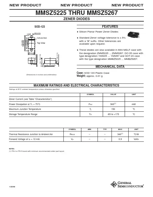
This is a complete series of zener diodes with limits and excellent operating characteristics that reflect the
the superior capabilities of silicon-oxide passivated junctions. It is designed for use in hybrid thick and thin
film circuits.
Maximum Ratings
Characteristics Symbol Max Unit
Total Device Dissipation @T
A=25℃
P
tot 500 mW
Storage Temperature Tstg -65 to +175
°C
Junction Temperature Tj 175
°C
Mini-Melf 元器件交易网www.cecb2b.com
CYStech Electronics Corp.
Spec. No. : C326SM
Issued Date : 2003.07.31
Revised Date :
Page No. : 2/3
ZMM55CXXSM series
CYStek Product Specification Electrical Characteristics
(T
L=30℃, unless otherwise noted, V
F=1.0V Max @I
F=100mA for all types.)
Test
Current Maximum Zener
Impedance
(Note 2) Maximum Reverse
Leakage Current
Device Nominal
Zener
Voltage
Vz at Iz
T
(V)
(Note1) I
ZT(mA) Z
ZT at
I
ZT
(Ω) Z
ZK at
I
ZK=1mA
(Ω) Typical
Temperature
Coefficient
(%/℃)
I
R
(μA) Test
Voltage
(V) Maximum
Regulation
Current
I
ZM(mA)
(Note 3)
ZMM55C2V4 2.28-2.56 5 85 600 -0.070 50 1.0 150
ZMM55C2V7
2.5-2.9 5 85 600 -0.070
10 1.0 135
ZMM55C3V0
2.8-3.2 5 85 600 -0.070
4 1.0 125
ZMM55C3V3
3.1-3.5 5
85 600 -0.065 2 1.0
115
ZMM55C3V6
3.4-3.8 5
85 600 -0.060 2 1.0
105
ZMM55C3V9
3.7-4.1 5
85 600 -0.050 2 1.0
95
ZMM55C4V3
4.0-4.6 5
75 600 -0.025 1 1.0
90
ZMM55C4V7
4.4-5.0 5
60 600 -0.010 0.5 1.0
85
ZMM55C5V1
4.8-5.4 5
35 550 +0.015 0.1 1.0
80
ZMM55C5V6
5.2-6.0 5
25 450 +0.025 0.1 1.0
70
ZMM55C6V2 5.8-6.6 5
10 200 +0.035 0.1 2.0 64
ZMM55C6V8 6.4-7.2 5
8 150 +0.045 0.1 3.0 58
ZMM55C7V5 7.0-7.9 5 7 50 +0.050 0.1 5.0 53
ZMM55C8V2 7.7-8.7 5 7 50 +0.050 0.1 6.0 47
ZMM55C9V1 8.5-9.6 5 10 50 +0.060 0.1 7.0 43
ZMM55C10 9.4-10.6 5 15 70 +0.070 0.1 7.5 40
ZMM55C11
10.4-11.6 5 20 70 +0.070 0.1 8.5 36
ZMM55C12
11.4-12.7 5 20 90 +0.070 0.1
9.0 32
ZMM55C13
12.4-14.1 5
26 110 +0.070
0.1
10 29
ZMM55C15
13.8-15.6 5
30 110 +0.070
0.1
11 27
ZMM55C16
15.3-17.1 5
40 170 +0.070
0.1
12 24
ZMM55C18
16.8-19.1 5
50 170 +0.070
0.1
14 21
ZMM55C20
18.8-21.2 5
55 220 +0.070 0.1
15 20
ZMM55C22 20.8-23.3 5 55 220 +0.070 0.1 17 18
ZMM55C24
22.8-25.6 5 80 220 +0.080 0.1
18 16
ZMM55C27
25.1-28.9 5
80 220 +0.080
0.1
20 14
ZMM55C30
28-32 5
80 220 +0.080
0.1
22 13
ZMM55C33
31-35 5
80 220 +0.080
0.1
24 12
ZMM55C36
34-38 5
80 220 +0.080
0.1
27 11
ZMM55C39
37-41 2.5 90 500 +0.080
0.1
30 10
ZMM55C43
40-46 2.5
90 600 +0.080
0.1
33 9.2
ZMM55C47
44-50 2.5
110 700 +0.080
0.1
36 8.5
Note: 1.The type numbers listed have zener voltage min/max as shown. Device tolerance of ±2% are indicated by a “B”
instead of a “C”. Zener voltage is measured with the device junction in thermal equilibrium at the lead temperature
of 30℃±1℃.
2.Z
ZT and Z
ZK are measured by dividing the ac voltage drop across the device by the ac current applied. The specified
limits are for I
Z(ac) =0.1I
Z(dc) with the ac frequency = 1k Hz.
3.This data was calculated using nominal voltages. The maximum current handling capability on a worse case basis is
limited by the actual zener voltage at the operating point and the powered derating curve.
元器件交易网www.cecb2b.com