
机器视觉数字式LED光源控制器使用说明书
- 格式:pdf
- 大小:735.64 KB
- 文档页数:10

. NETWORK PARING:1. Pairing with Zigbee HubFUNCTIONS OF DIFFERENT INDICATOR COLORS SHOWN AS FOLLOWING TABLE :(RGBCCT >RGBW >RGB >CCT >DIMMER >RGBCCT)Add the device to a zigbee network via coordinator or hub① Please ensure the device wasn’t be paired.Otherwise, please “RESET” the device according to the part Ⅱ “RESET”.③ Open the zigbee App (hue or Amazon Alexa), add the device.② After STEP 1, there will be a pairing process about 90s.Once times out, you need to repeat the ①.Different color indicators correspond to different functions.② ResetShort press once to switch frequency; Short press twice to enter find and binding;Short press three times to enter touchlink; Short press four times to clear the zigbee network.③ OPTShort press once to switch the function; Press and hold for more than 5 seconds to set the power-on status.④ If the pairing done successfully after the above steps, the device will blink 3 times.③④2. TouchLink to a Zigbee Remote Control / Touch Panel ① Please make sure the distance between the device and remote control/ touch panel less than 10cm;Method 2: Re-power on the device, Touchlink Commissioning will start after 15 seconds if it’s not added to a ZigBee network, 165 seconds timeout. Or start immediately if it’s already added to a network, 180 seconds timeout. Once timeout, repeat the operation.② Method 1: Please short press key “Reset” 3 times or power on/off the device 3 times to enter into “Touchlink Commissioning” mode, the device will blink 5 times.(Flash 3 times)<10cm③ Set the remote / touch panel to enter “Touchlink Commissioning”.Please refer to the manual of the corresponding remote / touch panel.④ There shall be indication on the remote or touch panel for successful pairing, the device will blink 2 times. Now the device shall be controllable via the remote / touch panel.*Note:① If the device & remote control in different zigbee network, each remote can link with one device.② If the device & remote control in the same zigbee network, max 30 remotes can link with one device.③ For the Philips Hue /Amazon Echo Plus, the device & remote control should in the same network before TouchLink.3. Find and Bind Mode4. Pairing with 2.4GHz RF Remote Control / Touch Panel*Note: Make sure that the device & remote are in the same network.Please refer to the manual of the corresponding remote / touch panel.The device will blink twice , and start “Find and Bind” mode to nd the “Target Node”.① Short press “Reset” button (or re-power on the device)for 2 times.① The pairing will be timeout after 4 seconds when the device powered on.③ The indications from the device will blink 3 times.② The pairing will be done successfully by pressing any zone “On” key of the 2.4G RF Remote or touch panel.② Set the remote control / touch panel (target node) to enter the “Find and Bind” mode to search for “Bind Initiator”.Now the device shall be remote control / touch panel controllable.③ “Find and Bind” is completed, the remote / touch panel shall have indication.Any zone “On”Short press once(Power on the device, within 4s)SPECIFICATIONInput VoltageDC12-24-36-48-54 V Size 125x37x24mm Model NO.Product Name GL-C-001P 5 in 1 Smart LED Controller Max Protection Rate IP20Total Power 270 W Max Total Output Current 5 A Max Operating TemperatureCommon Anode Constant Voltage-20℃~45℃600Hz800Hz 1000Hz 2000Hz 4000Hz 8000Hz Flashing times123456. RESET:1. RESET the Zigbee Network2. Frequency Settings1. RGBCCT: . FACTORY RESET:(Short press for 4 times)(Long press for 5 seconds)① Method 1: Delete the device on theAPP, the device will blink 3 times.② Method 2: Short press key “Reset” 4 times (Or re-power on the device 4 times) to unpair the network, the device will blink 3 times.Method 1:Method 2:Method 1:Method 2:2. RESET the 2.4GHz RF Network① Method 1: Short press the Master “On” key 5 times within 4 seconds after the device powered on, the device will blink 3 times.Under RGBCCT function, the RGBCCT strip can be connected to the device.2. RGBW:Under RGBW function, the RGBW strip can be connected, without any connection to “N” terminal.4. CCT:Under CCT function, two pieces of CCT strips can be connected, without any connection to “N” terminal.In order to be applicable to different power supplies, the frequency of device is selectable as 600Hz 、800Hz 、1000Hz 、2000Hz 、4000Hz 、8000Hz with default frequency 1000HZ. Once short pressing “Reset” key , the frequency will switch into the next one. The indicator will flash in Pink color and resume to previous color after “off” for 2 seconds. The rule of indicator flashing times for different frequency please refer to table.1. Power-on Status Settings3. RGB:Under RGB function, the RGB strip can be connected, without any connection to “N” terminal.② Method 2: Short press continuously 5 times the Zone “On” key the device being paired within 4 seconds after the device powered on, the device will blink 3 times.Short press for 5 times(Power on the device, within 4s)Short press for 5 times(Power on the device, within 4s)“On” button of Zone 1-6 which is pairingThe Factory Reset will be done successfully by long pressing “Reset” key more than 5 seconds (or re-power on the device 5 times or more). All configuration parameters will be reset after the device is reset or removed from the network, including ZigBee and 2.4G RF Network. The indicator will flash firstly 3 times in the color of corresponding function selected, and turn into default White color (Default RGBCCT function) after flashing 4 times again .. WIRING DIAGRAM:POWER ON STATUS & FREQUENCY SETTINGS. SATURATION CONTROL FUNCTION VIA 2.4G RF REMOTE CONTROL. V+R G B C W5. DIMMER:1000Hz > 2000Hz > 4000Hz > 8000Hz > 600Hz >800Hz > 1000HzUnder dimmer function, five pieces of single color strips can be connected.Long press “opt” key for more than 5 seconds , the indicator will flash in light blue color and resume to previous color after “off” for 4 seconds to complete power-on status setting. The default power-on status is light on. The indicator flashing 3 times in light blue means light on under power-on status, flashing 4 times in light blue means light off under power-on status.。
LED显示屏控制软件操作手册☞您使用LED显示屏控制软件,本软件适用于常规类LED控制卡(例如U盘LED控制卡,串口LED控制卡,网口LED控制卡等)。
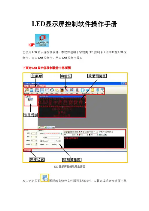
下面为LED显示屏控制软件主界面图LED显示屏控制软件主界面双击光盘里面图标的安装包文件即可安装软件,安装完成后会在桌面出现图标,双击图标,即可进入LED显示屏控制软件的主界面。
☞下面是软件详细的操作说明控制卡查找和显示屏设置控制卡连接好显示屏和电脑后点击工具栏里面的查找屏查找屏使用串口卡或者网口卡连接会在红色字体区域自动显示控制卡的型号和版本号▲(注:使用U盘控制卡可以忽略查找屏步骤,直接设置屏参,编辑好节目点击发送即可)①点击屏参设置按钮设置屏参②输入密码168输入密码③设置好屏参后点击设置屏参按钮屏参设置▲(注:设置屏参里面有一些常用的单元板参数供参考选择)☞下面是一些常见的LED单元板的参数设置推荐1,如果是户外P10的屏,接口是12接口的:(单色)屏参为:数据极性:低,OE极性:高扫描方式: 1/4 扫描,默认4.1扫描方式2,如果是户外P16的屏,接口是12接口的:屏参为:数据极性:低,OE极性:高扫描方式: 1/4 扫描中的4.3扫描方式3,如果是户内φ3.75,φ5 的屏,接口是08接口的:屏参为:数据极性:低,OE极性:低扫描方式: 1/16 扫描4,如果是车载屏P7.62的屏,接口是08接口的:屏参为:数据极性:低,OE极性:低扫描方式: 1/8 扫描▲(注:以上推荐参数都是市面LED单元板的常见参数设置,不排除特殊规格的LED单元板,请以实际情况为准)编辑节目和节目类型介绍①设置好屏参后首先点击工具栏里面的节目按钮即可进入节目编辑节目②点击节目编号可以设置节目播放时段和次数③在工具栏选择不同的节目类型可以进一步详细编辑节目内容1.字幕型节目,在超文本RTF型文件节目中,RTF超文本可对每个字符设置字体、大小,不同的颜色,并可以单独保持该节目的超文本文件,以便以后恢复使用。

一、概述SWP-LED数字显示控制仪适用于各种温度、压力、液位、速度、长度等的测量控制。
采用微处理器进行数学运算,可对各种非线性信号进行高精度的线性矫正。
SWP-LED数字显示控制仪向用户开启了仪表内部参数(包括输入类型、运算方式、输出参数、通讯参数等)的设定界面。
SWP-LED数字显示控制仪可切换输入十九种分度号。
采用先进的无跳线技术,更改输入分度号时,不用更改跳线或开关。
整个仪表改型过程不需断电,只需设定仪表的分度号及相关参数,即可在线完成输入分度号的更改。
SWP-LED数字显示控制仪支持多机通讯,具有多种标准串行双向通讯功能,可选择多种通讯接口方式(如RS-232C、RS-485、RS-422等),通讯波特率300-9600bps仪表内部参数自由设定。
可与各种带串行输入输出的设备(如电脑、PLC、DCS等)进行通讯,构成智能管理系统。
配用数据采集器和组态王等诸多工控组态软件,可方便的实现多台仪表与上位机进行联网管理。
二、主要特点1、全新概念的计算机数字自动调校.测量值零点迁移功能.测量值增益放大功能.冷端补偿值零点迁移功能.冷端补偿增益放大功能.变送输出值零点迁移功能.变送输出值增益放大功能2、清晰明确的测量值显示.高清晰LED数字显示测量值3、支持多机网络通讯,通讯协议可任意自由设定4、独特的全开放式用户自设定界面.输入信号类型设定.测量值零点与量程范围设定.报警方式设定.输出方式设定5、设定参数断电永久保留及参数密码锁定6、全数字化冷端补偿.可选择外接冷端补偿(适用于高精度测量场合).可选择仪表内部冷端补偿7、七种规格外形结构尺寸仪表型号SWP-C80SWP-S80SWP-C90仪表外形外形尺寸160×80×140mm80×160×140mm96×96×140mm 开孔尺寸152×76mm76×152mm92×92mm仪表型号SWP-C40SWP-S40SWP-C70SWP-C10仪表外形外形尺寸96×48×140mm48×96×140mm72×72×110mm48×48×110mm 开孔尺寸92×46mm46×92mm68×68mm44×44mm三、输入信号与适配传感器1、热电偶输入B、S、K、E、J、T、WRe分度号2、热电阻输入Pt100、Cu503、标准电流输入0-10mA(输入阻抗≤500Ω)4-20mA(输入阻抗≤250Ω)4、标准电压输入0-5V(输入阻抗≥250kΩ)1-5V(输入阻抗≥250kΩ)5、电阻(远传压力表)输入30-350Ω6、其他电流输入0-20mA等电流信号(按用户要求定制)7、其他电压输入0-10V、0-100V等电压信号(按用户要求定制)四、主要技术指标输入信号热电偶标准热电偶B、S、K、E、J、T、WRe等电阻标准热电阻Pt10、Pt100、Cu50和远传压力表电阻输出电流0-10mA、4-20mA、0-20mA等(输入阻抗≤250Ω)电压0-5V、1-5V、0-10V、0-100V等(输入阻抗≥250kΩ)测量范围-1999~9999字测量精度0.5%FS±1字分辨率热电偶输入时为1字(显示值为整数、无小数点)Pt100.1电阻输入(量程为-99.9~199.9℃)时为0.1字Pt100、Cu50、Pt10电阻输入时为1字远传压力表输入时为1字电流和电压输入时可选1字、0.1字、0.01字和0.001字温度补偿0-50℃显示方式-1999~9999测量值显示-1999~9999设定值显示发光二极管工作状态显示控制方式位式ON/OFF带回差输出信号模拟量输出0-10mA(负载能力≤750Ω)4-20mA(负载能力≤500Ω)0-5V(输出能力≤250Ω)1-5V(输出能力≤250Ω)开关量输出继电器控制输出(继电器ON/OFF带回差)触点容量AC220V/3A;DC24V/6A(阻性负载)可控硅控制输出SCR可控硅过零触发脉输出,可触发可控硅400V/100A固态继电器输出SSR固态继电器控制信号输出(6-24V/30mA,电压不可调)通讯输出接口方式标准通信接口RS-485,RS-232C,RS-422等波特率300-9600bps内部自由设定馈电输出DC24V,负载能力≤30mA控制方式可选择1-4个继电器输出(ON/OFF带回差)控制精度±1字报警方式可选择1-4个继电器输出(ON/OFF带回差)报警精度±1字温度补偿0-50℃数字式温度自动补偿参数设定面板轻触式按键数字设定参数设定值断电后永久保存参数设定值密码锁定保护方式输入回路断线报警(热电偶或电阻输入时),状态LED指示输入超/欠量程报警电源欠压自动复位工作异常自动复位(Watch Dog)联机通讯通讯接口为二线制、三线制或四线制(如RS-485、RS-232C、RS-422等),亦可由用户特殊要求,波特率300-9600bps可由仪表内部参数自由设定。

cst光源控制器说明书
1、工作模式0,将该通道设置为软件触发常亮模式。
可由按键触发和通信触发。
工作模式0为最常规的工作模式,也是目前市场上的标准模式,在此模式下,光源接驳到数字光源控制器上属于常亮的,我们通过PWM调节脉宽的方式来调节光源的亮度。
2、工作模式1,将改通道设置为软件触发闪光模式。
可由按键触发和通信触发。
工作模式1,设计此模式的目的是通过软件的方式模拟接触到外部硬件触发信号的方式来控制光源瞬间进行通断。
3、工作模式2,将该通道设置为外部触发闪光模式,上升沿触发。
只能由输入端口触发。