诺基亚6500C官方拆机教程
- 格式:doc
- 大小:1.37 MB
- 文档页数:20
《转帖》:只是让大家参观,千万不要拿自己的爱机开刀!!!诺基亚E71可以说是当前在市面上非常受到大家关注的一款商务机型,其金属的机身,灵巧的身形再搭配上QWERTY的全键盘以及320万像素的自动对焦摄像头均让大家垂涎不已,面对与这款诺基亚的超强商务机,对其很有一种蠢蠢欲动想拆了它看窥探下内部结构的的冲动,然而可怜的是尽管周边有不少朋友在用E71,但是就没一个肯借给我拆,而偶又舍不得扔弃自己的胖子(palm)去入手一台E71。
呜呜呜呜!为了要满足自己的拆机兽欲,偶四处寻找商家看是否有机可拆,最后在软磨硬泡之下从某商家手上抢到了这款正在正常服务的E71!于是乎......螺丝刀、铁锤、铁钳所有工具都找了出来,早已把商家“要小心好好对待我的爱机啊”之类的话语抛于脑后,脑袋中一直是如何拆机,拆开后会是怎样的内容。
在一堆工具中,发现只需要螺丝刀就能够吧诺基亚E71拆开,哪么其他工具全统统收起来吧,下面我们便来看看整个拆解的步骤以及E71的全钢结构吧。
为诺基亚E71默哀一番先吧螺丝刀的第一作用,拆下四颗螺丝这两个小金属扣是关键哦。
否则拆不开E71拆开上盖了,拆上盖有点难度哦螺丝刀第二作用,继续拆两颗螺丝这款金属挡板拆了1分钟才能完好的拆下,倒扣扣的很紧挡板拆掉了......终于都看下拆下来的上面板,金属质感一流的呢背面还是很具金属感拆Qwerty键盘咯Qwerty键盘连体形很好Qwerty为了保持手感,添加了不锈钢金属框架的支持继续拆,想看主板,不过必须先把屏幕拆开拆开屏幕排线,发现屏幕和键盘是连在一齐的E71键盘和屏幕是紧贴在不锈钢中板上的哦拆掉键盘连接主板的排线把屏幕键盘拿下来拆掉屏幕和键盘后的E71只剩主板贴在钢板上的屏幕和键盘感觉非常的安全诺基亚E71的听筒也在钢板上外壳不锈钢,中层不锈钢,看来E71非常的硬钢板结构稳重,拗一下...真的很硬侧面的按键也贴在钢板上E71的直板做工很好,接口配件质量优秀金属屏蔽罩把芯片都盖住了想拆了屏蔽罩看下芯片都没法看,很郁闷哦E71还有红外线接口,之前都没什么发现30万像素的视频摄像头非常的小...这颗就是E71上的320万像素自动对焦摄像头了把摄像头拆下来看看才行oh...yeah...320万像素自动对焦的摄像头只是TF卡的一半大小这样看起来没有什么反转过来后...很多外接设备拆完了...看下诺基亚E71的拆解全家福吧拆机总结:对于这款大家极为关注的诺基亚E71,通过拆机后我们发现其不仅机身的外壳采用了金属结构,并且机身的内部也采用了金属的框架来支撑,构造非常的合理,理论上会非常的耐用和耐摔,在此我们也体验到了诺基亚的精湛工艺。
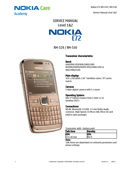
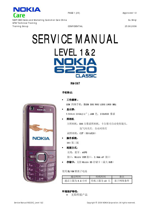
SERVICE MANUALLevel 1&2RM-529 / RM-530Transceiver characteristicsBand:GSM/EDGE 850/900/1800/1900WCDMA/HSDPA/HSUPA 850/1900/2100 or 900/1900/2100Main display:320 x 240 QVGA 2.36" 16million colors, TFT active matrixCamera:5 Mpix digital camera with 5 x zoomOperating System:S60 3rd Edition Feature Pack 2 (S60 3.2.3) Symbian OS9.3Connections:WLAN, Bluetooth 2.0 EDR, 3.5 mm Nokia Audio connecor, High-Speed 2.0 Micro-USB, Micro SD card (4GB in sales package)Transceiver with - battery packTalk timeStandbyGSM: 12 h 30 min GSM: 492 h Note:Talk times are dependant on network parameters and phone settingsTable of contents1. Change history (3)2. Copyright (4)3. Warnings and cautions (5)3.1 Warnings (5)3.2 Cautions (5)4. ESD protection (6)5. Care and maintenance (7)6. Battery information (8)7. Exploded view (9)8. Service devices (10)9. SW-update (11)10. Disassembly instructions (12)11. Assembly hints (19)12. Solder components (20)1.CHANGE HISTORYDate Comments Status VersionNo.Approved 1.0 31.8.2009The purpose of this document is to help NOKIA service levels 1 and 2 workshop technicians tocarry out service to NOKIA products. This Service Manual is to be used only by authorized NOKIAservice suppliers, and the content of it is confidential. Please note that NOKIA provides also otherguidance documents (e.g. Service Bulletins) for service suppliers, follow these regularly andcomply with the given instructions.While every endeavor has been made to ensure the accuracy of this document, some errors mayexist. If you find any errors or if you have further suggestions, please notify NOKIA using theaddress below:CMO Operation & LogisticsTraining and Vendor DevelopmentMultimedia Creation & Supportmailto:Service.Manuals@Please keep in mind also that this documentation is continuously being updated and modified,so watch always out for the newest version.2.COPYRIGHTCopyright © 2009 Nokia. All rights reserved.Reproduction, transfer, distribution or storage of part or all of the contents in this document inany form without the prior written permission of Nokia is prohibited.Nokia, Nokia Connecting People, and Nokia X and Y are trademarks or registered trademarks ofNokia Corporation. Other product and company names mentioned herein may be trademarks ortradenames of their respective owners.Nokia operates a policy of continuous development. Nokia reserves the right to make changesand improvements to any of the products described in this document without prior notice.Under no circumstances shall Nokia be responsible for any loss of data or income or any special,incidental, consequential or indirect damages howsoever caused.The contents of this document are provided “as is”. Except as required by applicable law, nowarranties of any kind, either express or implied, including, but not limited to, the impliedwarranties of merchantability and fitness for a particular purpose, are made in relation to theaccuracy, reliability or contents of this document. Nokia reserves the right to revise thisdocument or withdraw it at any time without prior notice.The availability of particular products may vary by region.IMPORTANTThis document is intended for use by qualified service personnel only.3.WARNINGS AND CAUTIONSPlease refer to the phone’s user guide for instructions relating to operation, care andmaintenance including important safety information. Note also the following:3.1Warnings1.CARE MUST BE TAKEN ON INSTALLATION IN VEHICLES FITTED WITH ELECTRONIC ENGINEMANAGEMENT SYSTEMS AND ANTI–SKID BRAKING SYSTEMS. UNDER CERTAIN FAULT CONDITIONS,EMITTED RF ENERGY CAN AFFECT THEIR OPERATION. IF NECESSARY, CONSULT THE VEHICLEDEALER/MANUFACTURER TO DETERMINE THE IMMUNITY OF VEHICLE ELECTRONIC SYSTEMS TO RFENERGY.2.THE HANDPORTABLE TELEPHONE MUST NOT BE OPERATED IN AREAS LIKELY TO CONTAINPOTENTIALLY EXPLOSIVE ATMOSPHERES, EG PETROL STATIONS (SERVICE STATIONS), BLASTINGAREAS ETC.3.OPERATION OF ANY RADIO TRANSMITTING EQUIPMENT, INCLUDING CELLULAR TELEPHONES, MAYINTERFERE WITH THE FUNCTIONALITY OF INADEQUATELY PROTECTED MEDICAL DEVICES. CONSULTA PHYSICIAN OR THE MANUFACTURER OF THE MEDICAL DEVICE IF YOU HAVE ANY QUESTIONS.OTHER ELECTRONIC EQUIPMENT MAY ALSO BE SUBJECT TO INTERFERENCE.3.2Cautions1.Servicing and alignment must be undertaken by qualified personnel only.2. Ensure all work is carried out at an anti–static workstation and that an anti–static wriststrap is worn.e only approved components as specified in the parts list.4.Ensure all components, modules screws and insulators are correctly re–fitted after servicingand alignment.5.Ensure all cables and wires are repositioned correctly4.ESD PROTECTIONNokia requires that service points have sufficient ESD protection (against staticelectricity) when servicing the phone.Any product of which the covers are removed must be handled with ESDprotection. The SIM card can be replaced without ESD protection if the productis otherwise ready for use.To replace the covers ESD protection must be applied.All electronic parts of the product are susceptible to ESD. Resistors, too, can bedamaged by static electricity discharge.All ESD sensitive parts must be packed in metallized protective bags duringshipping and handling outside any ESD Protected Area (EPA).Every repair action involving opening the product or handling the productcomponents must be done under ESD protection.ESD protected spare part packages MUST NOT be opened/closed out of an ESDProtected Area.For more information and local requirements about ESD protection and ESDProtected Area, contact your local Nokia After Market Services representative.5.CARE AND MAINTENANCEThis product is of superior design and craftsmanship and should be treated with care. Thesuggestions below will help you to fulfil any warranty obligations and to enjoy this product formany years.∙Keep the phone and all its parts and accessories out of the reach of small children.∙Keep the phone dry. Precipitation, humidity and all types of liquids or moisture can contain minerals that will corrode electronic circuits.∙Do not use or store the phone in dusty, dirty areas. Its moving parts can be damaged.∙Do not store the phone in hot areas. High temperatures can shorten the life of electronic devices, damage batteries, and warp or melt certain plastics.∙Do not store the phone in cold areas. When it warms up (to its normal temperature), moisture can form inside, which may damage electronic circuit boards.∙Do not drop, knock or shake the phone. Rough handling can break internal circuit boards.∙Do not use harsh chemicals, cleaning solvents, or strong detergents to clean the phone.∙Do not paint the phone. Paint can clog the moving parts and prevent proper operation.∙Use only the supplied or an approved replacement antenna. Unauthorised antennas, modifications or attachments could damage the phone and may violate regulationsgoverning radio devices.All of the above suggestions apply equally to the product, battery, charger or any accessory.6.BATTERY INFORMATIONNote: A new battery’s full performance is achieved only after two or three complete charge anddischarge cycles! The battery can be charged and discharged hundreds of times but it willeventually wear out.When the operating time (talk-time and standby time) is noticeably shorter than normal, it istime to buy a new battery. Use only batteries approved by the phone manufacturer andrecharge the battery only with the chargers approved by the manufacturer.Unplug the charger when not in use. Do not leave the battery connected to a charger for longerthan a week, since overcharging may shorten its lifetime.If left unused a fully charged battery will discharge itself over time Temperature extremes canaffect the ability of your battery to charge.For good operation times with Ni-Cd/NiMh batteries, discharge the battery from time to time byleaving the product switched on until it turns itself off (or by using the battery discharge facilityof any approved accessory available for the product).Do not attempt to discharge the battery by any other means Use the battery only for itsintended purpose.Never use any charger or battery which is damaged.Do not short-circuit the battery. Accidental short-circuiting can occur when a metallic object(coin, clip or pen) causes direct connection of the + and - terminals of the battery (metal stripson the battery) for example when you carry a spare battery in your pocket or purse.Shortcircuiting the terminals may damage the battery or the connecting object.Leaving the battery in hot or cold places, such as in a closed car in summer or winter conditions,will reduce the capacity and lifetime of the battery. Always try to keep the battery between 15°Cand 25°C (59°F and 77°F).A phone with a hot or cold battery may temporarily not work, even when the battery is fullycharged. Batteries’ performance is particularly limited in temperatures well below freezing.Do not dispose batteries in a fire! Dispose of batteries according to local regulations (e.g.recycling).Do not dispose as household waste.7.EXPLODED VIEWOnly available as assemblyThese parts can not be reused after removalVer.1.0A1=UI SHIELD ASSY (I0005-I0008)A2=LIGHT SWAP PACKAGE (I0010-I0011)A3=B-COVER ASSY (I0016-I0025)A-COVER ASSYI0001LCD AM COG 240x320I0004AUDIO GASKETI0007POWER KEYI0017SIDE-KEYSI0014AV-FLEX ASSEMBLYI0018SD DOOR I0016SCREW 1.8x5.0I0027GPS BT WLAN ANTENNA MODULEI0024EARP 32R 8x12x2I0008IHF SPEAKERI0020IHF SPEAKER GASKETI0021CAM MOD 5MPI0012OPERATOR COVER ASSY I0002SCREW M1.4X5.0TORX PLUS 4IP I0009KEYMAT I0003UI-FLEX ASSEMBLY I0005UI SHIELD I0006LIGHT SWAP PWB I0010BATTERY COVER I0028ANTENNA ASSY I00262YD FLASH LED ASSY I0013TYPE LABEL I0011DC-JACK I0023B COVER I0025USB DOOR I00158. SERVICE DEVICESFLS-5 Flash DeviceCA-101 Service CableAC-3 Travel ChargerBL-4S BatteryNMP standard toolkit (v2) For more information, refer to the Service Bulletin (SB-011) on NOKIA Online. Supplier or manufacturer contacts for tool re-order can be found in “Recommended service equipment” document on NOKIA Online.9.SW-UPDATEFlash concept- (Point of Sales)To use the FLS-5 Flash Dongle, follow the user guide inside the sales package.Please check always for the latest version of flash software, wich is available on Nokia Online.10.DISASSEMBLY INSTRUCTIONS1) Nokia E72 disassembly.2) You must use the Nokia Standard Toolkit version2 + the SS-210 camera removal tool.3) To open the BATTERY COVER slide the release button to the direction shown. Then lift up the bottom end of the BATTERY COVER and remove it to the shown direction.4) Unscrew the two TORX + size 4 screws in theorder shown. Do not use them again.4) Insert the SRT-6 between the A-COVER ASSEMBLY and the B-COVER ASSEMBLY. Slide it from top to bottom to release the clip holding the A-COVER ASSEMBLY.6) Using the same procedure release also the clip onopposite side of the A-COVER.7) Finally release the clip on the bottom side of the device by sliding the SRT-6 along the edge. Then separate the A-COVER ASSEMBLY by first lifting the bottom side up and then pulling it towards the keymat.8) Separate the A-COVER and the KEYMAT.9) Carefully loosen the adhesive between the A-COVER and the OPERATOR COVER ASSEMBLY and separate them. Do not use the OPERATOR COVER ASSEMBLY again. Discard it10) Protect both sides of the A-COVER window withprotective film.11) Protect the LCD with protective film.12) Open the LCD connector with the SS-93. Be careful not to damage the connector or thecomponents nearby!13) Unscrew the four TORX + size 6 screws in the order shown. Note that these screws can be reused. Do not discard them!14) Lift up the UI SHIELD ASSY together with the LCDas shown.15) Open the UI FLEX connector with the SS-93. Be careful not to damage the connector or nearby components!16) Remove the UI SHIELD ASSY with LCD.17) Carefully press with fingers through the UI SHIELD ASSY opening so that the LCD releases.18) Remove the LCD.19) Use the dental tool to release the EARPIECE. Be careful not to injure yourself with the sharp end of the dental tool! Remove the earpiece with tweezers. Do not use it again. 20) Remove also the AUDIO GASKET with the dental tool. Discard the AUDIO GASKET. Discard also the UISHIELD ASSEMBLY21) Before the PWB can be removed, the USB DOORhas to be opened.22) Remove the PWB.23) Insert the SS-210 camera removal tool on top ofthe CAMERA. A) Press the CAMERA down a little bitwith the black plastic parts of the SS-210, otherwisesocket locking pins are damaged when metal platesare pressed down. B) Press metal sheets down, asshown in small picture.24) Press metal plates from the sides to tightenthem to the CAMERA and then lift up the CAMERA.25) Remove the SIDE KEYS with tweezers.26) Push the USB DOOR holder through the small hole and remove the USB DOOR.27) Remove the FLASH LED ASSEMBLY with tweezers. Do not use it again. Discard it.28) Remove the POWER KEY with tweezers.29) Lever out the DC JACK with the dental tool and remove it with tweezers. Discard it.30) Lift up the ANTENNA ASSEMBLY with the dental tool and remove it.31) Carefully release the small part of the AV FLEX ASSEMBLY attached to the B-COVER with dental tool. Then lever out the AV FLEX ASSEMBLY with the dental tool.32) Remove the AV FLEX ASSEMBLY with tweezers.33) Carefully lift up the IHF SPEAKER with the dental tool and remove it with tweezers. Discard it. Do not use it again. 34) Release also the IHF MESH with the dental tool. Remove it with tweezers and discard it. Do not useit again.35) To release the GPS BT WLAN ANTENNA first leverit out with the dental tool as shown …36) … and then remove it with tweezers.37) Finally rotate the SD CARD DOOR to vertical position and pull the holder through the small opening.38) Nokia E72 disassembly is now complete.-END OF DISASSEMBLY-11.ASSEMBLY HINTS1) Tighten the two TORX + size 4 screws to the torque of 12 Ncm in the order shown. 2) Tighten the four TORX + size 6 screws to the torque of 25 Ncm in the order shown.12.SOLDER COMPONENTSF1400F3300X1501X7550X2401F2000X2450G2200X7551X1500S2400Ver.1.0。

对于这款4英寸屏幕,搭载Symbian^3操作系统的顶级商务手机诺基亚E7来说,无论是诺基亚,还是我们广大的玩家,都对诺基亚E7给予了很高的期望。
相信有不少朋友已经入手诺基亚E7了,但对于一些玩家来说,用手机是次要的,最主要的还是对手机进行“暴力”拆机,而这也是大家想要看到。
今天给大家带来的就是诺基亚E7的拆机教程图解,不知道看过之后你会不会也有一种想要拆机的冲动呢!下面进入正题。
拆机前的准备工序:1、将手机关机2、取出SIM卡槽3、准备工具:六角T5螺丝刀、最小号十字螺丝刀、镊子、拆机拨片、风枪(也可用电吹风代替)首先打开诺基亚E7顶部的HDMI接口盖用T5螺丝刀拧下螺丝:然后用拨片或者指甲掀开HDMI右侧的盖板(下面用双面胶链接,掀开时请小心):然后用拨片或者指甲掀开HDMI右侧的盖板(下面用双面胶链接,掀开时请小心):然后用拨片或者指甲掀开HDMI右侧的盖板(下面用双面胶链接,掀开时请小心):拧下盖板下面的螺丝拧下来后双手攥住手机,然后用两个拇指向前推动盖板部位(因为作者要留一个手拍照,所以无法解放双手):不用很大力气就推下来了。
如果此处吃力,可以尝试用指甲等工具从上盖两侧边先向外翘下:然后我们来拆底部的盖子,首先要小心的揭下这个盖板(也是用双面胶粘的):先用刀片或者镊子之类的翘起一个角,然后慢慢的掀起来:之后拧下底部露出来的这颗螺丝,然后按照下图放方式推开底盖:上下端盖都拆掉了,我们可以看到大后盖的螺丝了:分别拧下这四个角的螺丝:接下来我们来拆键盘,首先拧开顶部的转轴锁定螺丝:此时转轴已经可以90°翻开了,然后掀开手机,用最小号的十字螺丝刀拧下键盘上面的4颗螺丝:螺丝全部拧下后再由上边开始掀开键盘,要慢慢的向外用力,因为键盘下面有少许双面胶粘合。
由于键盘为金属制造,所以要保证不能使金属变形:键盘拿下来后就可以看到键盘的电路板了:然后用指甲或者拨片从边上轻轻的撬开铝合金外壳边缘:掀开铝合金后盖(注意:此处是从侧面掀开的,掀开时不要用力过猛,让铝合金外壳变形就麻烦了):看到电池了:如果大家只是为了换电池,那么看到这里就可以了,电池已经可以完全的拿下来了,如果您还有更高层次的追求,那么请随悟空继续往下拆。

Symbians60v3格机教程-诺基亚6120C论坛6122C论坛-塞班智能...Symbian s60v3格机教程有很多朋友都在使用塞班平台的智能手机。
智能手机可以安装各种用途的软件,使用很方便,然而软件带来的问题也比较多。
据统计,智能手机80%以上的问题都是由软件造成,比如无故的关机,某些程序打不开等。
软件问题的原因比较复杂,所以不宜解决,而格式化手机就成了比较快捷有效的方法了,所以本人整理了一下格式化手机的方法在这分享一下。
当你的手机出现问题时,先不要发愁,也不要忙着找售后,自己先格式化试试。
首先要纠正两点误区:1.有人认为格式化手机是很危险的,弄不好手机就变砖头了,其实这并不正确,只要你操作正确,格式化手机是很安全的,就像开关机一样。
2.有人说格式化手机是高手做的事,其实也不是,格式化手机是很简单的,只要五分钟你就能学会。
在此有必要解释一下格式化手机的原理:多数塞班第三版的手机内都有四个盘符,个别机型有五个,我们以大多数的四个盘符为例,分别为C盘、D盘、E盘、Z盘,一般情况下这些盘符是看不见的,只要下载一个第三方的文件管理器就能看到了。
C盘就是系统盘,相等于电脑的C盘;D盘是缓存盘,就是RAM,相当于电脑的内存;E盘就是你的储存卡;Z盘是只读的ROM盘,里面存有手机系统的原始数据。
而我们要格的就是手机的C盘,而格式化的过程就是将Z盘数据覆盖C盘数据的过程,原理和电脑的重装系统差不多。
现在我们要做的就是格式化之前的准备了,这是最重要的,不然可能产生严重的后果。
1.备份手机里的有用的数据,包括电话本,信息,储存在手机内(储存卡内的没关系)的相片、歌曲等文件,因为格式化手机后,手机内的所有数据将丢失。
2.格机前请先删除你自己安装的所有软件,因为格机后部分程序储存在手机里的数据将丢失,可能会造成程序用不了又删不掉的情况,当然,这不会对手机产生什么不良后果,不过还是删掉好。
2.格式化之前一定要保证手机电量充足,中途没电手机就真变砖头啦!3.格机时不要插充电器。

诺基亚6700S官方拆机教程更多原装配件,可登录以下网址/?userId=&shopId=35322983&view_type=& order_type=&search出师表两汉:诸葛亮先帝创业未半而中道崩殂,今天下三分,益州疲弊,此诚危急存亡之秋也。
然侍卫之臣不懈于内,忠志之士忘身于外者,盖追先帝之殊遇,欲报之于陛下也。
诚宜开张圣听,以光先帝遗德,恢弘志士之气,不宜妄自菲薄,引喻失义,以塞忠谏之路也。
宫中府中,俱为一体;陟罚臧否,不宜异同。
若有作奸犯科及为忠善者,宜付有司论其刑赏,以昭陛下平明之理;不宜偏私,使内外异法也。
侍中、侍郎郭攸之、费祎、董允等,此皆良实,志虑忠纯,是以先帝简拔以遗陛下:愚以为宫中之事,事无大小,悉以咨之,然后施行,必能裨补阙漏,有所广益。
将军向宠,性行淑均,晓畅军事,试用于昔日,先帝称之曰“能”,是以众议举宠为督:愚以为营中之事,悉以咨之,必能使行阵和睦,优劣得所。
亲贤臣,远小人,此先汉所以兴隆也;亲小人,远贤臣,此后汉所以倾颓也。
先帝在时,每与臣论此事,未尝不叹息痛恨于桓、灵也。
侍中、尚书、长史、参军,此悉贞良死节之臣,愿陛下亲之、信之,则汉室之隆,可计日而待也。
臣本布衣,躬耕于南阳,苟全性命于乱世,不求闻达于诸侯。
先帝不以臣卑鄙,猥自枉屈,三顾臣于草庐之中,咨臣以当世之事,由是感激,遂许先帝以驱驰。
后值倾覆,受任于败军之际,奉命于危难之间,尔来二十有一年矣。
先帝知臣谨慎,故临崩寄臣以大事也。
受命以来,夙夜忧叹,恐托付不效,以伤先帝之明;故五月渡泸,深入不毛。
今南方已定,兵甲已足,当奖率三军,北定中原,庶竭驽钝,攘除奸凶,兴复汉室,还于旧都。
此臣所以报先帝而忠陛下之职分也。
至于斟酌损益,进尽忠言,则攸之、祎、允之任也。
愿陛下托臣以讨贼兴复之效,不效,则治臣之罪,以告先帝之灵。
若无兴德之言,则责攸之、祎、允等之慢,以彰其咎;陛下亦宜自谋,以咨诹善道,察纳雅言,深追先帝遗诏。
SERVICE MANUALLevel 1&2RM-484 / RM-485 / RM-486Transceiver characteristicsBand:RM-484:WCDMA 900/1900/2100 + WLAN + GSM/ GPRS/ EGPRSGSM 850/900/1800/1900 MHzRM-485:WCDMA 850/1900/2100 + WLAN + GSM/ GPRS/ EGPRSGSM 850/900/1800/1900 MHzRM-486:GSM/ GPRS/ EGPRS 850/900/1800/1900 MHzDisplay:2.6" QVGA 320x240 AM OLED, 16 M coloursKeypad:Alphanumeric keypad and Multimedia keypadCamera:8 MP AF Carl Zeiss, Dual LED Flash with Heptagonmicro-optics lens, secondary camera CIFOperating System:S60 3rd edition, feature pack 3 (PPD 53.32 R3)Connections:2 mm charger, 3,5 mm AV connector, Bluetooth 2.0EDR, Micro USB 2,0, A-GPS, WLAN 802.11b/g, TV outTransceiver with BL-5K battery packTalk time Standby NoteGSM:Up to 6.3 hours WCDMA:Up to 3.9 hours GSM:Up to 315 hoursWCDMA:Up to 275 hoursTalk times aredependant onnetworkparameters andphone settingsTable of contents1. Change history (3)2. Copyright (4)3. Warnings and cautions (5)3.1 Warnings (5)3.2 Cautions (5)4. ESD protection (6)5. Care and maintenance (7)6. Battery information (8)7. Exploded view (9)8. Service devices (10)9. SW-update (11)10. Disassembly instruction (12)11. Assembly hints (19)12. Solder components (20)1.CHANGE HISTORYDate Comments Status VersionNo.Approved 1.0 22.04.2009The purpose of this document is to help NOKIA service levels 1 and 2 workshop technicians tocarry out service to NOKIA products. This Service Manual is to be used only by authorized NOKIAservice suppliers, and the content of it is confidential. Please note that NOKIA provides also otherguidance documents (e.g. Service Bulletins) for service suppliers, follow these regularly andcomply with the given instructions.While every endeavor has been made to ensure the accuracy of this document, some errors mayexist. If you find any errors or if you have further suggestions, please notify NOKIA using theaddress below:CMO Operation & LogisticsTraining and Vendor DevelopmentMultimedia Creation & Supportmailto:Service.Manuals@Please keep in mind also that this documentation is continuously being updated and modified,so watch always out for the newest version.2.COPYRIGHTCopyright © 2009 Nokia. All rights reserved.Reproduction, transfer, distribution or storage of part or all of the contents in this document inany form without the prior written permission of Nokia is prohibited.Nokia, Nokia Connecting People, and Nokia X and Y are trademarks or registered trademarks ofNokia Corporation. Other product and company names mentioned herein may be trademarks ortradenames of their respective owners.Nokia operates a policy of continuous development. Nokia reserves the right to make changesand improvements to any of the products described in this document without prior notice.Under no circumstances shall Nokia be responsible for any loss of data or income or any special,incidental, consequential or indirect damages howsoever caused.The contents of this document are provided “as is”. Except as required by applicable law, nowarranties of any kind, either express or implied, including, but not limited to, the impliedwarranties of merchantability and fitness for a particular purpose, are made in relation to theaccuracy, reliability or contents of this document. Nokia reserves the right to revise thisdocument or withdraw it at any time without prior notice.The availability of particular products may vary by region.IMPORTANTThis document is intended for use by qualified service personnel only.3.WARNINGS AND CAUTIONSPlease refer to the phone’s user guide for instructions relating to operation, care andmaintenance including important safety information. Note also the following:3.1Warnings1.CARE MUST BE TAKEN ON INSTALLATION IN VEHICLES FITTED WITH ELECTRONIC ENGINEMANAGEMENT SYSTEMS AND ANTI–SKID BRAKING SYSTEMS. UNDER CERTAIN FAULT CONDITIONS,EMITTED RF ENERGY CAN AFFECT THEIR OPERATION. IF NECESSARY, CONSULT THE VEHICLEDEALER/MANUFACTURER TO DETERMINE THE IMMUNITY OF VEHICLE ELECTRONIC SYSTEMS TO RFENERGY.2.THE HANDPORTABLE TELEPHONE MUST NOT BE OPERATED IN AREAS LIKELY TO CONTAINPOTENTIALLY EXPLOSIVE ATMOSPHERES, EG PETROL STATIONS (SERVICE STATIONS), BLASTINGAREAS ETC.3.OPERATION OF ANY RADIO TRANSMITTING EQUIPMENT, INCLUDING CELLULAR TELEPHONES, MAYINTERFERE WITH THE FUNCTIONALITY OF INADEQUATELY PROTECTED MEDICAL DEVICES. CONSULTA PHYSICIAN OR THE MANUFACTURER OF THE MEDICAL DEVICE IF YOU HAVE ANY QUESTIONS.OTHER ELECTRONIC EQUIPMENT MAY ALSO BE SUBJECT TO INTERFERENCE.3.2Cautions1.Servicing and alignment must be undertaken by qualified personnel only.2. Ensure all work is carried out at an anti–static workstation and that an anti–static wriststrap is worn.e only approved components as specified in the parts list.4.Ensure all components, modules screws and insulators are correctly re–fitted after servicingand alignment.5.Ensure all cables and wires are repositioned correctly4.ESD PROTECTIONNokia requires that service points have sufficient ESD protection (against static electricity) when servicing the phone.Any product of which the covers are removed must be handled with ESD protection. The SIM card can be replaced without ESD protection if the product is otherwise ready for use.To replace the covers ESD protection must be applied.All electronic parts of the product are susceptible to ESD. Resistors, too, can be damaged by static electricity discharge.All ESD sensitive parts must be packed in metallized protective bags during shipping and handling outside any ESD Protected Area (EPA).Every repair action involving opening the product or handling the product components must be done under ESD protection.ESD protected spare part packages MUST NOT be opened/closed out of an ESD Protected Area.For more information and local requirements about ESD protection and ESD Protected Area, contact your local Nokia After Market Services representative.5.CARE AND MAINTENANCEThis product is of superior design and craftsmanship and should be treated with care. Thesuggestions below will help you to fulfil any warranty obligations and to enjoy this product formany years.∙Keep the phone and all its parts and accessories out of the reach of small children.∙Keep the phone dry. Precipitation, humidity and all types of liquids or moisture can contain minerals that will corrode electronic circuits.∙Do not use or store the phone in dusty, dirty areas. Its moving parts can be damaged.∙Do not store the phone in hot areas. High temperatures can shorten the life of electronic devices, damage batteries, and warp or melt certain plastics.∙Do not store the phone in cold areas. When it warms up (to its normal temperature), moisture can form inside, which may damage electronic circuit boards.∙Do not drop, knock or shake the phone. Rough handling can break internal circuit boards.∙Do not use harsh chemicals, cleaning solvents, or strong detergents to clean the phone.∙Do not paint the phone. Paint can clog the moving parts and prevent proper operation.∙Use only the supplied or an approved replacement antenna. Unauthorised antennas, modifications or attachments could damage the phone and may violate regulationsgoverning radio devices.All of the above suggestions apply equally to the product, battery, charger or any accessory.6.BATTERY INFORMATIONNote: A new battery’s full performance is achieved only after two or three complete charge anddischarge cycles! The battery can be charged and discharged hundreds of times but it willeventually wear out.When the operating time (talk-time and standby time) is noticeably shorter than normal, it istime to buy a new battery. Use only batteries approved by the phone manufacturer andrecharge the battery only with the chargers approved by the manufacturer.Unplug the charger when not in use. Do not leave the battery connected to a charger for longerthan a week, since overcharging may shorten its lifetime.If left unused a fully charged battery will discharge itself over time Temperature extremes canaffect the ability of your battery to charge.For good operation times with Ni-Cd/NiMh batteries, discharge the battery from time to time byleaving the product switched on until it turns itself off (or by using the battery discharge facilityof any approved accessory available for the product).Do not attempt to discharge the battery by any other means Use the battery only for itsintended purpose.Never use any charger or battery which is damaged.Do not short-circuit the battery. Accidental short-circuiting can occur when a metallic object(coin, clip or pen) causes direct connection of the + and - terminals of the battery (metal stripson the battery) for example when you carry a spare battery in your pocket or purse.Shortcircuiting the terminals may damage the battery or the connecting object.Leaving the battery in hot or cold places, such as in a closed car in summer or winter conditions,will reduce the capacity and lifetime of the battery. Always try to keep the battery between 15°Cand 25°C (59°F and 77°F).A phone with a hot or cold battery may temporarily not work, even when the battery is fullycharged. Batteries’ performance is particularly limited in temperatures well below freezing.Do not dispose batteries in a fire! Dispose of batteries according to local regulations (e.g.recycling).Do not dispose as household waste.7.EXPLODED VIEWOnly available as assemblyVer. 1.0These parts can not be reused after removalEARPIECE I0003DUSTNET EARPIECEI0002DISPLAY OLED AM 240x320I0007CROSS SLOTTED SCREWI0103MM KEYMAT DOMESHEETI0203LIGHT SWAP PWBI0205CAMERA MOD CMOS 8MPI0207AV-JACK I02082SS 2ND ENGINE MODULEI0214CAMERA BEZEL ASSYI0215TEST PAD COVER LABELI0216IHF SPEAKERI0210IHF ADHESIVEI0209SCREW TORX+ 6I0218C-COVER ASSYI0219SLIDE FPC ASSY I0101SLIDE MODULE I0102ITU-T KEYMAT I0201TYPE LABEL I0206IHF SPEAKER I0210IHF ADHESIVE I0209B-COVER I0211ANTENNA ASSY I0212WATERINGRESS LABEL I9998CONNECTION FLEX ASSY I0213SCREW TORX+ 4I0217SCREW TORX+ 6I0202ITU-T KEYMAT DOMESHEET I0202S60 FPC ASSY I0004A-COVER I0001A1 =A-COVER ASSY (I0001-I0004)A3 =B-COVER ASSY (I0208-I0215, I9998)A2 = LIGHT SWAP CTR (ENGINE) GLOBAL (I0203-I0206)8.SERVICE DEVICESFLS-5 Flash Device CA-101 Service Cable AC-10 Travel ChargerBL-5K Battery SS-182 Camera Removal ToolNMP standard toolkit (v2)For more information, refer to theService Bulletin (SB-011) on NOKIAOnline. Supplier or manufacturercontacts for tool re-order can befound in “Recommended serviceequipment” document on NOKIAOnline.9.SW-UPDATEFlash concept- (Point of Sales)To use the FLS-5 Flash Dongle, follow the user guide inside the sales package.Please check always for the latest version of flash software, wich is available on Nokia Online.10.DISASSEMBLY INSTRUCTION1) Nokia N86 8MP disassembly 1) You must use the Nokia Standard Toolkit version2 and the SS-182 camera removal tool.3) Protect the front cover with a protective film. 4) Release the BATTERY COVER and remove it.5) Turn the phone and slide it open. 6) Use the SS-93 to release the keymat and removeit by pulling it.7) Close the slide. 8) Unscrew the four TORX+ size 6 screws in theorder shown. Do not use them again.9) Then unscrew these two TORX + size 4 screws inthe order shown. Do not use them again.10) Lift the upper block to gain access to the SLIDEFPC assy connector.11) Disconnect the SLIDE FPC assy from the engineboard. Be careful to not to damage the connector ornearby components.12) Remove the upper block.13) Unscrew the two TORX + size 6 screws in the order shown. Do not use them again.14) Carefully lift up the LIGHT SWAP PWB to gainaccess to the CONNECTION FLEX ASSY.15) Carefully disconnect the CONNECTION FLEX from the PWB with the SS-93.16) The LIGHT SWAP PWB can now be removed.17) Release the ITU-T DOMESHEET and the MMDOMESHEET with the dental tool and peel them off. Do not use them again.18) Detach the first clip of the CAMERA BEZELassembly with the sharp end of the SS-93.19) Turn the lower block and release the second clip of the CAMERA BEZEL assembly. Then remove the assembly.20) Use the sharp end of the SS-93 to release the2SS 2ND ENGINE MODULE from B-COVER ASSY.while removing the 2nd engine module.22) Use the dental tool to release the IHF speaker. The IHF adhesive cannot be reused.23) Use the dental tool to release the second IHF speaker. The IHF adhesive cannot be reused.24) Push out the AV connector with the AV plug and remove the connector with the tweezers.25) Use the SS-93 to detach the antenna and then remove it. 26) Disconnect the CONNECTION FLEX from the 2SS 2ND ENGINE MODULE with the SS-93. Be careful withthe components around the connector!27) Unscrew the two Phillips size 00 screws in theorder shown. Do not use them again.28) Drag the slide to the opposite side.29) Then unscrew these two Phillips size 00 screwsin the order shown. These screws cannot be usedagain.30) Detach the SLIDE MODULE from the A-COVER assyby lifting it up with the SS-93.31) Lift up the SLIDE MODULE slightly and use the SS-93 to disconnect the SLIDE FPC assembly. Be careful to not to damage the connector.32) The slide assy can now be removed.33) Disconnect the LCD connector with the SS-93. 34) Lift the LCD up with the SS-93 and remove theLCD.35) Lift up the EARPIECE with the dental tool andthen remove it. Remove the DUSTNET EARPIECE withthe tweezers. It cannot be reused.36) Carefully detach the S 60 FPC assembly with theSS-93 and remove the assembly.37) Release the SLIDE FPC ASSY with the SS-93. Do not use it again. Discard it.38) Nokia N86 8MP disassembly is now complete.-END OF DISASSEMBLY-11.ASSEMBLY HINTS1) INDIGO VARIANT: Tighten the two Phillips size 00 screws to the torque of 6 Ncm in the order shown.WHITE VARIANT: Tighten the two Phillips size 00 screws to the torque of 8 Ncm in the order shown.2) Drag the slide to the opposite direction.INDIGO VARIANT: Tighten the two Phillips size 00 screws to the torque of 6 Ncm in the order shown.WHITE VARIANT: Tighten the two Phillips size 00 screws to the torque of 8 Ncm in the order shown.3) Tighten the two TORX + size 6 screws to the torque of 16 Ncm in the order shown.4) Tighten the two TORX + size 4 screws to thetorque of 10 Ncm in the order shown.two5) Tighten the four TORX + size 6 screws to the torque of 18 Ncm in the order shown.12. SOLDER COMPONENTSSolder components only for Level 2V2422S2542S2541X7551X7550S2543X3300F3300V2427Ver. 1.0V2420X1000V2428V2429V2421。
SERVICE MANUAL Level 1&2RM-465Transceiver characteristicsBand:GSM 850/900/1800/1900 WCDMA 900/1900/2100Display:2,4" QVGA (320x240), 16M coloursKeypad:Full QWERTY keyboardCamera:Main camera: 3,2 Mpix Secondary camera; VGAOperating System:Series 60 release 3.2Connections:2 mm charger, 3,5 mm AV connector, Bluetooth 2.0 EDR, USB 2.0 (Micro USB), A-GPS, WLAN 802.11b/gTransceiver with BL-4U battery packTalk timeStandby NoteGSM:up to 5,3 hours WCDMA :Up to 4.2 hours GSM: Up to 300 hours WCDMA: Up to 270 hours Talk times are dependant on networkparameters andphone settingsTable of contents1. Change history (3)2. Copyright (4)3. Warnings and cautions (5)3.1 Warnings (5)3.2 Cautions (5)4. ESD protection (6)5. Care and maintenance (7)6. Battery information (8)7. Exploded view (9)8. Service devices (10)9. SW-update (11)10. Disassembly instruction (12)11. Assembly hints (19)12. Solder components (21)1.CHANGE HISTORYDate Comments Status VersionNo.Approved 1.0 24.04.2009The purpose of this document is to help NOKIA service levels 1 and 2 workshop technicians tocarry out service to NOKIA products. This Service Manual is to be used only by authorized NOKIAservice suppliers, and the content of it is confidential. Please note that NOKIA provides also otherguidance documents (e.g. Service Bulletins) for service suppliers, follow these regularly andcomply with the given instructions.While every endeavor has been made to ensure the accuracy of this document, some errors mayexist. If you find any errors or if you have further suggestions, please notify NOKIA using theaddress below:CMO Operation & LogisticsTraining and Vendor DevelopmentMultimedia Creation & Supportmailto:Service.Manuals@Please keep in mind also that this documentation is continuously being updated and modified,so watch always out for the newest version.2.COPYRIGHTCopyright © 2009 Nokia. All rights reserved.Reproduction, transfer, distribution or storage of part or all of the contents in this document inany form without the prior written permission of Nokia is prohibited.Nokia, Nokia Connecting People, and Nokia X and Y are trademarks or registered trademarks ofNokia Corporation. Other product and company names mentioned herein may be trademarks ortradenames of their respective owners.Nokia operates a policy of continuous development. Nokia reserves the right to make changesand improvements to any of the products described in this document without prior notice.Under no circumstances shall Nokia be responsible for any loss of data or income or any special,incidental, consequential or indirect damages howsoever caused.The contents of this document are provided “as is”. Except as required by applicable law, nowarranties of any kind, either express or implied, including, but not limited to, the impliedwarranties of merchantability and fitness for a particular purpose, are made in relation to theaccuracy, reliability or contents of this document. Nokia reserves the right to revise thisdocument or withdraw it at any time without prior notice.The availability of particular products may vary by region.IMPORTANTThis document is intended for use by qualified service personnel only.3.WARNINGS AND CAUTIONSPlease refer to the phone’s user guide for instructions relating to operation, care andmaintenance including important safety information. Note also the following:3.1Warnings1.CARE MUST BE TAKEN ON INSTALLATION IN VEHICLES FITTED WITH ELECTRONIC ENGINEMANAGEMENT SYSTEMS AND ANTI–SKID BRAKING SYSTEMS. UNDER CERTAIN FAULT CONDITIONS,EMITTED RF ENERGY CAN AFFECT THEIR OPERATION. IF NECESSARY, CONSULT THE VEHICLEDEALER/MANUFACTURER TO DETERMINE THE IMMUNITY OF VEHICLE ELECTRONIC SYSTEMS TO RFENERGY.2.THE HANDPORTABLE TELEPHONE MUST NOT BE OPERATED IN AREAS LIKELY TO CONTAINPOTENTIALLY EXPLOSIVE ATMOSPHERES, EG PETROL STATIONS (SERVICE STATIONS), BLASTINGAREAS ETC.3.OPERATION OF ANY RADIO TRANSMITTING EQUIPMENT, INCLUDING CELLULAR TELEPHONES, MAYINTERFERE WITH THE FUNCTIONALITY OF INADEQUATELY PROTECTED MEDICAL DEVICES. CONSULTA PHYSICIAN OR THE MANUFACTURER OF THE MEDICAL DEVICE IF YOU HAVE ANY QUESTIONS.OTHER ELECTRONIC EQUIPMENT MAY ALSO BE SUBJECT TO INTERFERENCE.3.2Cautions1.Servicing and alignment must be undertaken by qualified personnel only.2. Ensure all work is carried out at an anti–static workstation and that an anti–static wriststrap is worn.e only approved components as specified in the parts list.4.Ensure all components, modules screws and insulators are correctly re–fitted after servicingand alignment.5.Ensure all cables and wires are repositioned correctly4.ESD PROTECTIONNokia requires that service points have sufficient ESD protection (against static electricity) when servicing the phone.Any product of which the covers are removed must be handled with ESD protection. The SIM card can be replaced without ESD protection if the product is otherwise ready for use.To replace the covers ESD protection must be applied.All electronic parts of the product are susceptible to ESD. Resistors, too, can be damaged by static electricity discharge.All ESD sensitive parts must be packed in metallized protective bags during shipping and handling outside any ESD Protected Area (EPA).Every repair action involving opening the product or handling the product components must be done under ESD protection.ESD protected spare part packages MUST NOT be opened/closed out of an ESD Protected Area.For more information and local requirements about ESD protection and ESD Protected Area, contact your local Nokia After Market Services representative.5.CARE AND MAINTENANCEThis product is of superior design and craftsmanship and should be treated with care. Thesuggestions below will help you to fulfil any warranty obligations and to enjoy this product formany years.∙Keep the phone and all its parts and accessories out of the reach of small children.∙Keep the phone dry. Precipitation, humidity and all types of liquids or moisture can contain minerals that will corrode electronic circuits.∙Do not use or store the phone in dusty, dirty areas. Its moving parts can be damaged.∙Do not store the phone in hot areas. High temperatures can shorten the life of electronic devices, damage batteries, and warp or melt certain plastics.∙Do not store the phone in cold areas. When it warms up (to its normal temperature), moisture can form inside, which may damage electronic circuit boards.∙Do not drop, knock or shake the phone. Rough handling can break internal circuit boards.∙Do not use harsh chemicals, cleaning solvents, or strong detergents to clean the phone.∙Do not paint the phone. Paint can clog the moving parts and prevent proper operation.∙Use only the supplied or an approved replacement antenna. Unauthorised antennas, modifications or attachments could damage the phone and may violate regulationsgoverning radio devices.All of the above suggestions apply equally to the product, battery, charger or any accessory.6.BATTERY INFORMATIONNote: A new battery’s full performance is achieved only after two or three complete charge anddischarge cycles! The battery can be charged and discharged hundreds of times but it willeventually wear out.When the operating time (talk-time and standby time) is noticeably shorter than normal, it istime to buy a new battery. Use only batteries approved by the phone manufacturer andrecharge the battery only with the chargers approved by the manufacturer.Unplug the charger when not in use. Do not leave the battery connected to a charger for longerthan a week, since overcharging may shorten its lifetime.If left unused a fully charged battery will discharge itself over time Temperature extremes canaffect the ability of your battery to charge.For good operation times with Ni-Cd/NiMh batteries, discharge the battery from time to time byleaving the product switched on until it turns itself off (or by using the battery discharge facilityof any approved accessory available for the product).Do not attempt to discharge the battery by any other means Use the battery only for itsintended purpose.Never use any charger or battery which is damaged.Do not short-circuit the battery. Accidental short-circuiting can occur when a metallic object(coin, clip or pen) causes direct connection of the + and - terminals of the battery (metal stripson the battery) for example when you carry a spare battery in your pocket or purse.Shortcircuiting the terminals may damage the battery or the connecting object.Leaving the battery in hot or cold places, such as in a closed car in summer or winter conditions,will reduce the capacity and lifetime of the battery. Always try to keep the battery between 15°Cand 25°C (59°F and 77°F).A phone with a hot or cold battery may temporarily not work, even when the battery is fullycharged. Batteries’ performance is particularly limited in temperatures well below freezing.Do not dispose batteries in a fire! Dispose of batteries according to local regulations (e.g.recycling).Do not dispose as household waste.7. EXPLODED VIEWOnly available as assemblyVer. 1.0These parts can not be reused after removalA1=LIGHT SWAP PACKAGE (I0204-I0206, I9998)A2=B-COVER ASSEMBLY (I0211-I0214)EARPIECE HOLDER METALI0007T9 KEYMAT ASSEMBLY I0003LCD AM 240x320I0006SLIDE MODULEI01012RS UI FLEX ASSEMBLY I0009EARPIECE I0008LIGHT SWAP PWBI0205QWERTY DOMESHEET ASSY I0204TYPE LABEL I02062RP AV FLEX ASSYI0207VOLUME SIDE KEY ASSYI0217GPS/BT WLAN ANTENNAI0215B-COVER I0214ANTENNA ASSEMBLY I0216USB/SD-DOOR I0218DONAU SPEAKERI0212IHF FRONT GASKETI0213AUDIO ACCENT BAND I0219SCREW 1.4X3.4I0011SCREW RF1.6X4.5I01042RT CAMERA FLEX ASSEMBLY I0208BATTERY COVERI0223SCREW 1.4X2.5I0010FLEX SLIDER I01032RU DYNAMIC FLEX I0102FLEX PLANE I0201SCREW 1.8X3I0221SCREW 1.4X4.5I0222QWERTY KEYMAT I0202ACCENT BAND QWERTY I0203DC JACK I0211A-COVER ASSEMBLY I0002WINDOW ASSYI00018. SERVICE DEVICESFLS-5 Flash DeviceCA-101 Service CableAC-4 Travel ChargerBL-4U BatterySS-198 UI flex assembly jigNMP standard toolkit (v2) For more information, refer to the Service Bulletin (SB-011) on NOKIA Online. Supplier or manufacturer contacts for tool re-order can be found in “Recommended service equipment” document on NOKIA Online.9.SW-UPDATEFlash concept- (Point of Sales)To use the FLS-5 Flash Dongle, follow the user guide inside the sales package.Please check always for the latest version of flash software, wich is available on Nokia Online.10.DISASSEMBLY INSTRUCTION1) Nokia 5730 XpressMusic disassembly.2) You must use the Nokia Standard Toolkit version2.3) Remove the BATTERY COVER.4) Slide the phone open. Unscrew the first TORX+ 4 (M1,8 x 3) screw. Then unscrew the three TORX+ 4 (M1,4 x 2,5) screws in the order shown. Discardthem.5) Release the A-COVER ASSEMBLY from the SLIDE MODULE using the SRT-6. Carefully open the shown corner.6) Carefully lift up the top side of the A-COVER and at the same time push it to the left so that ITU KEYMATlatches open. Check that ITU latches are not broken.7) Remember to protect the LCD with protective film.8) Separate the KEYMAT ASSEMBLY from the A-COVERASSEMBLY.9) Release the EARPIECE HOLDER and remove it with the tweezers. Then separate the EARPIECE from the EARPIECE HOLDER with the tweezers.10) Open the LCD connector from the 2 MX UI FLEX ASSEMBLY with the SS-93. Be careful not to damage the connector.11) Carefully release the LCD with the SRT-6.12) Carefully lift up the LCD and push it into direction shown.13) Slide the phone open. 14) Use the SRT-6 to release the clips holding theACCENT BAND QWERTY.15) Use the SS-93 to detach the QWERTY KEYMATadhesive on the right side. Pull the QWERTY KEYMATin the direction shown.16) Remove the USB-DOOR by pulling it to thedirection shown.17) Turn the phone and use the SRT-6 to remove theAUDIO ACCENT BAND from the B-Cover Assembly.TIP: Use the SRT-6 NOKIA text facing up.18) Separate the AUDIO ACCENT BAND.19) Unscrew these five TORX+ size 4 screws in the order shown. Discard them.20) Close the slide a bit until the two screwsbecome visible (small image). Unscrew these three TORX+ size 4 screws.21) Rotate the SLIDE ASSY and unscrew the TORX+ size 4 screw.22) Use the SS-93 to open the locking mechanism ofthe Camera connector. Take out the SIDEKEYFLEX with the tweezers.23) Pull out the Camera connector with the tweezers and remove the Camera Assembly. Be careful not to damage the connector.24) Open the locking mechanism of AV connector with the SS-93 and pull out the connector with the tweezers.25) Use the SS-93 to lift the engine module and carefully separate it from the B-COVER.26) Remove the FLEX PLANE from the engine board by opening a small clip with the dental tool.27) Open the DYNAMIC FLEX connector with the SRT-6. Be careful not to damage the connector.28) Separate the engine board and the SLIDEMODULE.29) Remove the FLEX SLIDER using the SS-93.30) Open the connector of the DYNAMIC FLEX and separate it from the SLIDE MODULE. Be careful to notto damage the connector.31) Detach the 2 MX UI FLEX ASSEMBLY from the SLIDE MODULE with the SS-93. Discard the 2MX UI FLEX ASSEMBLY, do not use it again. Remove the adhesive stains from the SLIDE MODULE. 32) Start releasing the QWERTY DOMESHEET with the dental tool. Carefully remove the QWERTY DOMESHEET. Make sure that the whole QWERTYDOMESHEET is removed.33) Lift up the AV FLEX ASSY with the SS-93 andremove the ASSY with the tweezers.34) Remove the GPS/BT WLAN ANTENNA with thetweezers.35) Remove the ANTENNA ASSEMBLY with thetweezers.36) Release the DC JACK with the charger and thenremove the DC JACK with the tweezers.37) Use the dental tool to release the IHF SPEAKER and the IHF SPEAKER gasket. 38) Carefully push both buttons of the SIDE KEY with SS-93 to release it. Then remove the SIDE KEY withthe tweezers.-END OF DISASSEMBLY- 39) Nokia 5730 XpressMusic disassembly is nowcomplete.11.ASSEMBLY HINTS1) When placing the QWERTY DOMESHEET make sure that these holes are aligned. 2) First push the DYNAMIC FLEX with the SS-93 into place against the FLEX PLANE as shown. Next,connect the connector to the PWB. Then slide theFLEX PLANE into the gap and fasten the small clip.3) When assembling the other end of the DYNAMIC FLEX make sure that the connector goes under the two clips shown. Connect the connector and then press the FLEX SLIDER into the correct place so that the small gap is facing the DYNAMIC FLEX.4) Tighten the screw to the torque of 16 Ncm.5) Tighten the screws to the torque of 16 Ncm in the order shown. After tightening the first screw close the slide a bit until the two screw holes become visible (small image). Tighten the two TORX+ size 4 screws.6) Tighten the five TORX+ size 4 to the torque of 20Ncm in the order shown.7) Tighten the first three TORX+ size 4 screws (M1,4 x 2,5) to the torque of 20 Ncm in the order shown. Then tighten the last TORX+ size 4 screw (M1,8 x 3) to the torque of 20 Ncm.Nokia 5730 XpressMusic RM-465Service Manual Level 1&221 Confidential ∙ Copyright © 2009 NOKIA ∙ All rights reservedVersion 1.0 ISSUE 1 12. SOLDER COMPONENTS V2431V2426V2427V2429X1000X1451X1001。
SERVICE MANUAL Level 1&2RM-465Transceiver characteristicsBand:GSM 850/900/1800/1900 WCDMA 900/1900/2100Display:2,4" QVGA (320x240), 16M coloursKeypad:Full QWERTY keyboardCamera:Main camera: 3,2 Mpix Secondary camera; VGAOperating System:Series 60 release 3.2Connections:2 mm charger, 3,5 mm AV connector, Bluetooth 2.0 EDR, USB 2.0 (Micro USB), A-GPS, WLAN 802.11b/gTransceiver with BL-4U battery packTalk timeStandby NoteGSM:up to 5,3 hours WCDMA :Up to 4.2 hours GSM: Up to 300 hours WCDMA: Up to 270 hours Talk times are dependant on networkparameters andphone settingsTable of contents1. Change history (3)2. Copyright (4)3. Warnings and cautions (5)3.1 Warnings (5)3.2 Cautions (5)4. ESD protection (6)5. Care and maintenance (7)6. Battery information (8)7. Exploded view (9)8. Service devices (10)9. SW-update (11)10. Disassembly instruction (12)11. Assembly hints (19)12. Solder components (21)1.CHANGE HISTORYDate Comments Status VersionNo.Approved 1.0 24.04.2009The purpose of this document is to help NOKIA service levels 1 and 2 workshop technicians tocarry out service to NOKIA products. This Service Manual is to be used only by authorized NOKIAservice suppliers, and the content of it is confidential. Please note that NOKIA provides also otherguidance documents (e.g. Service Bulletins) for service suppliers, follow these regularly andcomply with the given instructions.While every endeavor has been made to ensure the accuracy of this document, some errors mayexist. If you find any errors or if you have further suggestions, please notify NOKIA using theaddress below:CMO Operation & LogisticsTraining and Vendor DevelopmentMultimedia Creation & Supportmailto:Service.Manuals@Please keep in mind also that this documentation is continuously being updated and modified,so watch always out for the newest version.2.COPYRIGHTCopyright © 2009 Nokia. All rights reserved.Reproduction, transfer, distribution or storage of part or all of the contents in this document inany form without the prior written permission of Nokia is prohibited.Nokia, Nokia Connecting People, and Nokia X and Y are trademarks or registered trademarks ofNokia Corporation. Other product and company names mentioned herein may be trademarks ortradenames of their respective owners.Nokia operates a policy of continuous development. Nokia reserves the right to make changesand improvements to any of the products described in this document without prior notice.Under no circumstances shall Nokia be responsible for any loss of data or income or any special,incidental, consequential or indirect damages howsoever caused.The contents of this document are provided “as is”. Except as required by applicable law, nowarranties of any kind, either express or implied, including, but not limited to, the impliedwarranties of merchantability and fitness for a particular purpose, are made in relation to theaccuracy, reliability or contents of this document. Nokia reserves the right to revise thisdocument or withdraw it at any time without prior notice.The availability of particular products may vary by region.IMPORTANTThis document is intended for use by qualified service personnel only.3.WARNINGS AND CAUTIONSPlease refer to the phone’s user guide for instructions relating to operation, care andmaintenance including important safety information. Note also the following:3.1Warnings1.CARE MUST BE TAKEN ON INSTALLATION IN VEHICLES FITTED WITH ELECTRONIC ENGINEMANAGEMENT SYSTEMS AND ANTI–SKID BRAKING SYSTEMS. UNDER CERTAIN FAULT CONDITIONS,EMITTED RF ENERGY CAN AFFECT THEIR OPERATION. IF NECESSARY, CONSULT THE VEHICLEDEALER/MANUFACTURER TO DETERMINE THE IMMUNITY OF VEHICLE ELECTRONIC SYSTEMS TO RFENERGY.2.THE HANDPORTABLE TELEPHONE MUST NOT BE OPERATED IN AREAS LIKELY TO CONTAINPOTENTIALLY EXPLOSIVE ATMOSPHERES, EG PETROL STATIONS (SERVICE STATIONS), BLASTINGAREAS ETC.3.OPERATION OF ANY RADIO TRANSMITTING EQUIPMENT, INCLUDING CELLULAR TELEPHONES, MAYINTERFERE WITH THE FUNCTIONALITY OF INADEQUATELY PROTECTED MEDICAL DEVICES. CONSULTA PHYSICIAN OR THE MANUFACTURER OF THE MEDICAL DEVICE IF YOU HAVE ANY QUESTIONS.OTHER ELECTRONIC EQUIPMENT MAY ALSO BE SUBJECT TO INTERFERENCE.3.2Cautions1.Servicing and alignment must be undertaken by qualified personnel only.2. Ensure all work is carried out at an anti–static workstation and that an anti–static wriststrap is worn.e only approved components as specified in the parts list.4.Ensure all components, modules screws and insulators are correctly re–fitted after servicingand alignment.5.Ensure all cables and wires are repositioned correctly4.ESD PROTECTIONNokia requires that service points have sufficient ESD protection (against static electricity) when servicing the phone.Any product of which the covers are removed must be handled with ESD protection. The SIM card can be replaced without ESD protection if the product is otherwise ready for use.To replace the covers ESD protection must be applied.All electronic parts of the product are susceptible to ESD. Resistors, too, can be damaged by static electricity discharge.All ESD sensitive parts must be packed in metallized protective bags during shipping and handling outside any ESD Protected Area (EPA).Every repair action involving opening the product or handling the product components must be done under ESD protection.ESD protected spare part packages MUST NOT be opened/closed out of an ESD Protected Area.For more information and local requirements about ESD protection and ESD Protected Area, contact your local Nokia After Market Services representative.5.CARE AND MAINTENANCEThis product is of superior design and craftsmanship and should be treated with care. Thesuggestions below will help you to fulfil any warranty obligations and to enjoy this product formany years.∙Keep the phone and all its parts and accessories out of the reach of small children.∙Keep the phone dry. Precipitation, humidity and all types of liquids or moisture can contain minerals that will corrode electronic circuits.∙Do not use or store the phone in dusty, dirty areas. Its moving parts can be damaged.∙Do not store the phone in hot areas. High temperatures can shorten the life of electronic devices, damage batteries, and warp or melt certain plastics.∙Do not store the phone in cold areas. When it warms up (to its normal temperature), moisture can form inside, which may damage electronic circuit boards.∙Do not drop, knock or shake the phone. Rough handling can break internal circuit boards.∙Do not use harsh chemicals, cleaning solvents, or strong detergents to clean the phone.∙Do not paint the phone. Paint can clog the moving parts and prevent proper operation.∙Use only the supplied or an approved replacement antenna. Unauthorised antennas, modifications or attachments could damage the phone and may violate regulationsgoverning radio devices.All of the above suggestions apply equally to the product, battery, charger or any accessory.6.BATTERY INFORMATIONNote: A new battery’s full performance is achieved only after two or three complete charge anddischarge cycles! The battery can be charged and discharged hundreds of times but it willeventually wear out.When the operating time (talk-time and standby time) is noticeably shorter than normal, it istime to buy a new battery. Use only batteries approved by the phone manufacturer andrecharge the battery only with the chargers approved by the manufacturer.Unplug the charger when not in use. Do not leave the battery connected to a charger for longerthan a week, since overcharging may shorten its lifetime.If left unused a fully charged battery will discharge itself over time Temperature extremes canaffect the ability of your battery to charge.For good operation times with Ni-Cd/NiMh batteries, discharge the battery from time to time byleaving the product switched on until it turns itself off (or by using the battery discharge facilityof any approved accessory available for the product).Do not attempt to discharge the battery by any other means Use the battery only for itsintended purpose.Never use any charger or battery which is damaged.Do not short-circuit the battery. Accidental short-circuiting can occur when a metallic object(coin, clip or pen) causes direct connection of the + and - terminals of the battery (metal stripson the battery) for example when you carry a spare battery in your pocket or purse.Shortcircuiting the terminals may damage the battery or the connecting object.Leaving the battery in hot or cold places, such as in a closed car in summer or winter conditions,will reduce the capacity and lifetime of the battery. Always try to keep the battery between 15°Cand 25°C (59°F and 77°F).A phone with a hot or cold battery may temporarily not work, even when the battery is fullycharged. Batteries’ performance is particularly limited in temperatures well below freezing.Do not dispose batteries in a fire! Dispose of batteries according to local regulations (e.g.recycling).Do not dispose as household waste.7. EXPLODED VIEWOnly available as assemblyVer. 1.0These parts can not be reused after removalA1=LIGHT SWAP PACKAGE (I0204-I0206, I9998)A2=B-COVER ASSEMBLY (I0211-I0214)EARPIECE HOLDER METALI0007T9 KEYMAT ASSEMBLY I0003LCD AM 240x320I0006SLIDE MODULEI01012RS UI FLEX ASSEMBLY I0009EARPIECE I0008LIGHT SWAP PWBI0205QWERTY DOMESHEET ASSY I0204TYPE LABEL I02062RP AV FLEX ASSYI0207VOLUME SIDE KEY ASSYI0217GPS/BT WLAN ANTENNAI0215B-COVER I0214ANTENNA ASSEMBLY I0216USB/SD-DOOR I0218DONAU SPEAKERI0212IHF FRONT GASKETI0213AUDIO ACCENT BAND I0219SCREW 1.4X3.4I0011SCREW RF1.6X4.5I01042RT CAMERA FLEX ASSEMBLY I0208BATTERY COVERI0223SCREW 1.4X2.5I0010FLEX SLIDER I01032RU DYNAMIC FLEX I0102FLEX PLANE I0201SCREW 1.8X3I0221SCREW 1.4X4.5I0222QWERTY KEYMAT I0202ACCENT BAND QWERTY I0203DC JACK I0211A-COVER ASSEMBLY I0002WINDOW ASSYI00018. SERVICE DEVICESFLS-5 Flash DeviceCA-101 Service CableAC-4 Travel ChargerBL-4U BatterySS-198 UI flex assembly jigNMP standard toolkit (v2) For more information, refer to the Service Bulletin (SB-011) on NOKIA Online. Supplier or manufacturer contacts for tool re-order can be found in “Recommended service equipment” document on NOKIA Online.9.SW-UPDATEFlash concept- (Point of Sales)To use the FLS-5 Flash Dongle, follow the user guide inside the sales package.Please check always for the latest version of flash software, wich is available on Nokia Online.10.DISASSEMBLY INSTRUCTION1) Nokia 5730 XpressMusic disassembly.2) You must use the Nokia Standard Toolkit version2.3) Remove the BATTERY COVER.4) Slide the phone open. Unscrew the first TORX+ 4 (M1,8 x 3) screw. Then unscrew the three TORX+ 4 (M1,4 x 2,5) screws in the order shown. Discardthem.5) Release the A-COVER ASSEMBLY from the SLIDE MODULE using the SRT-6. Carefully open the shown corner.6) Carefully lift up the top side of the A-COVER and at the same time push it to the left so that ITU KEYMATlatches open. Check that ITU latches are not broken.7) Remember to protect the LCD with protective film.8) Separate the KEYMAT ASSEMBLY from the A-COVERASSEMBLY.9) Release the EARPIECE HOLDER and remove it with the tweezers. Then separate the EARPIECE from the EARPIECE HOLDER with the tweezers.10) Open the LCD connector from the 2 MX UI FLEX ASSEMBLY with the SS-93. Be careful not to damage the connector.11) Carefully release the LCD with the SRT-6.12) Carefully lift up the LCD and push it into direction shown.13) Slide the phone open. 14) Use the SRT-6 to release the clips holding theACCENT BAND QWERTY.15) Use the SS-93 to detach the QWERTY KEYMATadhesive on the right side. Pull the QWERTY KEYMATin the direction shown.16) Remove the USB-DOOR by pulling it to thedirection shown.17) Turn the phone and use the SRT-6 to remove theAUDIO ACCENT BAND from the B-Cover Assembly.TIP: Use the SRT-6 NOKIA text facing up.18) Separate the AUDIO ACCENT BAND.19) Unscrew these five TORX+ size 4 screws in the order shown. Discard them.20) Close the slide a bit until the two screwsbecome visible (small image). Unscrew these three TORX+ size 4 screws.21) Rotate the SLIDE ASSY and unscrew the TORX+ size 4 screw.22) Use the SS-93 to open the locking mechanism ofthe Camera connector. Take out the SIDEKEYFLEX with the tweezers.23) Pull out the Camera connector with the tweezers and remove the Camera Assembly. Be careful not to damage the connector.24) Open the locking mechanism of AV connector with the SS-93 and pull out the connector with the tweezers.25) Use the SS-93 to lift the engine module and carefully separate it from the B-COVER.26) Remove the FLEX PLANE from the engine board by opening a small clip with the dental tool.27) Open the DYNAMIC FLEX connector with the SRT-6. Be careful not to damage the connector.28) Separate the engine board and the SLIDEMODULE.29) Remove the FLEX SLIDER using the SS-93.30) Open the connector of the DYNAMIC FLEX and separate it from the SLIDE MODULE. Be careful to notto damage the connector.31) Detach the 2 MX UI FLEX ASSEMBLY from the SLIDE MODULE with the SS-93. Discard the 2MX UI FLEX ASSEMBLY, do not use it again. Remove the adhesive stains from the SLIDE MODULE. 32) Start releasing the QWERTY DOMESHEET with the dental tool. Carefully remove the QWERTY DOMESHEET. Make sure that the whole QWERTYDOMESHEET is removed.33) Lift up the AV FLEX ASSY with the SS-93 andremove the ASSY with the tweezers.34) Remove the GPS/BT WLAN ANTENNA with thetweezers.35) Remove the ANTENNA ASSEMBLY with thetweezers.36) Release the DC JACK with the charger and thenremove the DC JACK with the tweezers.37) Use the dental tool to release the IHF SPEAKER and the IHF SPEAKER gasket. 38) Carefully push both buttons of the SIDE KEY with SS-93 to release it. Then remove the SIDE KEY withthe tweezers.-END OF DISASSEMBLY- 39) Nokia 5730 XpressMusic disassembly is nowcomplete.11.ASSEMBLY HINTS1) When placing the QWERTY DOMESHEET make sure that these holes are aligned. 2) First push the DYNAMIC FLEX with the SS-93 into place against the FLEX PLANE as shown. Next,connect the connector to the PWB. Then slide theFLEX PLANE into the gap and fasten the small clip.3) When assembling the other end of the DYNAMIC FLEX make sure that the connector goes under the two clips shown. Connect the connector and then press the FLEX SLIDER into the correct place so that the small gap is facing the DYNAMIC FLEX.4) Tighten the screw to the torque of 16 Ncm.5) Tighten the screws to the torque of 16 Ncm in the order shown. After tightening the first screw close the slide a bit until the two screw holes become visible (small image). Tighten the two TORX+ size 4 screws.6) Tighten the five TORX+ size 4 to the torque of 20Ncm in the order shown.7) Tighten the first three TORX+ size 4 screws (M1,4 x 2,5) to the torque of 20 Ncm in the order shown. Then tighten the last TORX+ size 4 screw (M1,8 x 3) to the torque of 20 Ncm.Nokia 5730 XpressMusic RM-465Service Manual Level 1&221 Confidential ∙ Copyright © 2009 NOKIA ∙ All rights reservedVersion 1.0 ISSUE 1 12. SOLDER COMPONENTS V2431V2426V2427V2429X1000X1451X1001。