
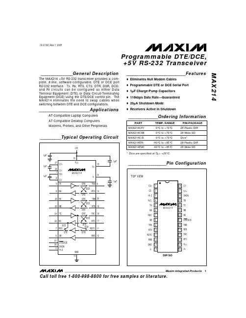
MAX214EWI-T中文资料
- 格式:pdf
- 大小:136.53 KB
- 文档页数:12


WiFi 6 high performance PoE Powered wireless connectivity for Small Office and Home OfficeThe NETGEAR WiFi 6 AX1800 PoE Wireless Access Point (AP) delivers 802.11ax high performance wireless connectivity for Small Office and Home Office (SOHO) deployments and supports dual band concurrent WiFi 6 operationsat 2.4GHz and 5GHz with a combinedthroughput of 1.8Gbps (600Mbps at2.4GHz and 1200Mbps at 5GHz). TheWAX214 WiFi 6 Access Point providesstandalone configuration with easy setup fora reliable, WiFi 6 802.11ax high performance,and cost effective wireless solution.The WAX214 can be powered by Power-over-Ethernet or a DC power adapter. FeaturesEasy to Configure• Simple setup in minutes with intuitive Graphical User Interface (GUI)• Comprehensive monitoring and management through a local web portal user interface802.11ax high performance and superior coverage• WiFi 6 802.11ax technology• Dual band concurrent operation between 2.4GHz and 5GHz frequency ranges• Maximize coverage for optimal deployment for SOHO Comprehensive security• Supports wireless security features(WPA, WPA2 and WPA3)• MAC based Access Control List toprotect against intruders• Block unwanted sites and servicesConvenient Deployment• Hardware harness included for easyceiling and wallmount installation• Flexible options for power source,either by a DC power adapter (includedin the WAX214PA model only) or by aPoE Ethernet switchInteroperate with both new andlegacy clients• Support latest WiFi 6 802.11ax wirelessclients to achieve maximum speed• Backward compatible to allow legacydevices to connect at their fastest speedSample Deployment Use CasesWAX214 Deployment ScenarioMicro Business Dental OfficesCar Repair ShopExample ApplicationWAX214 Deployment ScenarioLaptop PC, Tablet and SmartphoneConnects to desktop PC Cable/DSL modemPrinter and Surveillance CameraTechnical SpecificationsPhysical CharacteristicsPower Supply12V/1.5A (18W) Power adapter (included with WAX214PA model only) or PoE/PoE+ Switch Physical SpecificationsDimensions (L x W x H) 6.33 x 6.33 × 1.31 in160.9 × 160.9 x 33.28 mmWeight 0.84lb (380g)Mounting options Ceiling or WallmountNetwork InterfacesEthernet Ports One (1) 10/100/1000Mbps Ethernet (RJ-45) port with Auto Uplink™ (Auto MDI-X) ButtonsHardware Buttons Default ResetLEDs 4 LEDs (Power, LAN, 2.4GHz, 5GHz)Environmental SpecificationsOperating T emperature 0C to 40C (32F to 104F)Storage T emperature -40 to 70COperating Relative Humidity 95%Storage Humidity5-95%MTBF @ 25C > 1,896,453 hours @ 45C > 378,702 hoursSafety Certification CB, EN60950, EN62368 RF CharacteristicsStandards IEEE 802.11ac specification IEEE 802.11n 2.0 specification IEEE 802.11gIEEE 802.11bIEEE 802.11aIEEE 802.11axFrequency Band 2.4GHz and 5GHz concurrent operationMaximum Theoretical Throughput 573.5Mbps (2.4GHz) 1201Mbps (5GHz)Maximum Number of Clients128 (2.4GHz 64, 5GHz 128) Network ManagementDeployment options Standalone Web UIAccess Point Antenna: 3 dBi (2.4GHz) 4 dBi (5GHz)Security WiFi Protected Access (WPA2/WPA3) MAC Address filtering4 SSID*This product comes with a limited warranty that is valid only if purchased from a NETGEAR authorized reseller, and covers unmodifi ed hardware, fans and internal power supplies – not software or external power supplies, and requires product registration using the Insight mobile app or Insight Cloud portal within 90 days of purchase; see https:///about/warranty for details. Intended for indoor use only.**The NETGEAR OnCall 24x7 contract provides unlimited phone, chat and email technical support for your networking product.NETGEAR and the NETGEAR logo are trademarks and/or registered trademarks of NETGEAR, Inc. and/or its subsidiaries in the United States and/or other countries. Other brand names mentioned herein are for identification purposes only and may be trademarks of their respective holder(s). Information is subject to change without notice. © 2020 NETGEAR, Inc. All rights reserved.D-WAX214_16Nov20Technical SpecificationsNetwork ManagementMAC ACL Yes VPN Pass-through No802.11e WMM(Wireless multimedia mode) for QoS Simultaneous Bridge/Client AssociationNoWarranty and SupportHardware Limited Warranty3 years Next-Business-Day (NBD) Replacement YesT echnical support (online, phone)90 days free from date of purchase*ProSUPPORT OnCall 24x7 Service Packs**Category S2PMB0S12 (1 yr)PMB0S32 (3 yrs)PMB0S52 (5 yrs)Package ContentsWAX214WiFi 6 AX1800 Dual Band Wireless AP (WAX214)Ethernet cable Installation guideWarranty/support information cardPower adapter, available in WAX214PA-100NAS SKU onlyOrdering Information WAX214-100NAS(DC Power adapter not included)United States WAX214PA-100NAS (Power adapter included)United StatesWAX214-100EUS(DC Power adapter not included)Europe and Selected Countries。
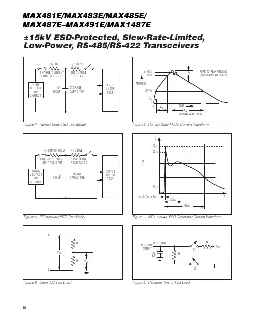
±15kV ESD-Protected, Slew-Rate-Limited,Low-Power, RS-485/RS-422 TransceiversFigure 6. IEC1000-4-2 ESD Test ModelFigure 8. Driver DC Test LoadFigure 7. IEC1000-4-2 ESD Generator Current WaveformFigure 9. Receiver Timing Test LoadFigure 4. Human Body ESD Test ModelFigure 5. Human Body Model Current Waveform MAX481E/MAX483E/MAX485E/MAX487E–MAX491E/MAX1487E10±15kV ESD-Protected, Slew-Rate-Limited, Low-Power, RS-485/RS-422 TransceiversIt takes the drivers and receivers longer to become enabled from the low-power shutdown state (t ZH(SHDN), t ZL(SHDN)) than from the operating mode (t ZH, t ZL). (The parts are in operating mode if the RE, DE inputs equal a logical 0,1 or 1,1 or 0, 0.)Driver Output Protection Excessive output current and power dissipation caused by faults or by bus contention are prevented by two mechanisms. A foldback current limit on the output stage provides immediate protection against short circuits over the whole common-mode voltage range (see Typical Operating Characteristics). In addition, a thermal shut-down circuit forces the driver outputs into a high-imped-ance state if the die temperature rises excessively.Propagation Delay Many digital encoding schemes depend on the differ-ence between the driver and receiver propagation delay times. Typical propagation delays are shown in Figures 19–22 using Figure 18’s test circuit.The difference in receiver delay times, t PLH- t PHL, is typically under 13ns for the MAX481E, MAX485E, MAX490E, MAX491E, and MAX1487E, and is typically less than 100ns for the MAX483E and MAX487E–MAX489E.The driver skew times are typically 5ns (10ns max) for the MAX481E, MAX485E, MAX490E, MAX491E, and MAX1487E, and are typically 100ns (800ns max) for the MAX483E and MAX487E–MAX489E.Typical Applications The MAX481E, MAX483E, MAX485E, MAX487E–MAX491E, and MAX1487E transceivers are designed for bidirectional data communications on multipoint bus transmission lines. F igures 25 and 26 show typical net-work application circuits. These parts can also be used as line repeaters, with cable lengths longer than 4000 feet. To minimize reflections, the line should be terminated at both ends in its characteristic impedance, and stub lengths off the main line should be kept as short as possi-ble. The slew-rate-limited MAX483E and MAX487E–MAX489E are more tolerant of imperfect termination. Bypass the V CC pin with 0.1µF.Isolated RS-485 For isolated RS-485 applications, see the MAX253 and MAX1480 data sheets.Line Length vs. Data Rate The RS-485/RS-422 standard covers line lengths up to 4000 feet. Figures 23 and 24 show the system differen-tial voltage for the parts driving 4000 feet of 26AWG twisted-pair wire at 110kHz into 100Ωloads.Figure 18. Receiver Propagation Delay Test Circuit MAX481E/MAX483E/MAX485E/MAX487E–MAX491E/MAX1487E Maxim Integrated13。