ROBOT程序例子
- 格式:pdf
- 大小:469.03 KB
- 文档页数:10

基于ROBOTSTUDIO的龙门焊接机器人的离线编程及虚拟装配简介近年来,随着工业自动化的不断发展,焊接机器人在制造业中得到了广泛应用。
传统的龙门焊接机器人通常需要在实际生产环境中进行编程和调试,这样会占用大量的时间和资源。
为了提高生产效率和降低成本,离线编程和虚拟装配成为了焊接机器人领域研究的热点。
本文将介绍基于ROBOTSTUDIO的龙门焊接机器人的离线编程及虚拟装配方法,以及其中的优势和应用。
ROBOTSTUDIO简介ROBOTSTUDIO是ABB公司推出的专业机器人离线编程软件,它可以用于模拟、优化和调试机器人系统,提供灵活的离线编程能力。
通过ROBOTSTUDIO,用户可以在计算机上进行机器人系统的设计、仿真和调试工作,减少了将机器人带入实际生产环境进行编程和调试的时间和成本。
ROBOTSTUDIO支持各种类型的机器人,包括龙门焊接机器人。
它提供了直观的用户界面和强大的功能,使用户能够轻松地完成离线编程和虚拟装配工作。
离线编程的优势离线编程是指在计算机上进行机器人程序的编写和调试,而不是在实际生产环境中。
离线编程具有以下几个优势:1.节省时间和成本:离线编程可以在计算机上进行,无需将机器人带入实际生产环境,因此可以节省大量的时间和成本。
2.提高安全性:离线编程可以在虚拟环境中进行,避免了在实际生产环境中进行编程时可能出现的安全风险。
3.提高生产效率:离线编程可以在不中断实际生产的情况下进行,可以在机器人实际操作之前进行优化和调试,从而提高生产效率。
4.便于修改和优化:离线编程可以随时进行修改和优化,无需将机器人带入实际生产环境,操作更加灵活方便。
龙门焊接机器人的离线编程及虚拟装配步骤步骤1:模型导入在ROBOTSTUDIO中,首先需要导入龙门焊接机器人的模型。
可以通过导入CAD文件或手动创建模型来完成这一步骤。
导入模型后,需要对模型进行正确的设置,包括定义关节坐标、工具和工件坐标等。
步骤2:程序编写在ROBOTSTUDIO中,可以使用ABB提供的RoboGuide语言进行程序编写。

FANUC机器人如何编写程序Robot 为自动化设备,但在自动化运转之前,必须先告诉Robot 要自动完成哪些动作,透过「撰写Robot 程序」可达到此目的。
Robot 程序主要由「动作指令」构成,只要熟悉手动操作Robot 的方式,将Robot 移动到欲记錄的位置,即可在「教点」的同时完成动作指令与Robot 程序。
本单元将介绍如何撰写简单的Robot 程序。
一、建立新程序(CREATE)与许多计算机软件一样,首先需要「开新档案」,建立一个新的Robot 程序。
按下进入Robot 程序选择一览表。
此时功能应显示为CREATE,若不是,请按切F1~F5的功能键至下一列,即可出现CREATE。
上图画面中,的右方有「>」符号,代表F1~F5 功能键有其他功能可供换。
按下CREATE 以建立一个新的Robot程序,此时显示以下画面等待输入程序名称:程序名称有以下限制:1. 不可与其他已存在的程序名称相同。
2. 由英文大写字母、數字、_(底线)组成。
3. 共1~8 个字符。
4. 第1个字必须是英文字母。
5. 中间不可有空格。
请先将教示盘的开关切换到ON的位置,程序名称输入完成请按兩次,进入程序编辑画面。
出现此画面代表新程序建立完成。
二、点位教导(Teaching)此时功能应显示为POINT,若不是,请按切换F1~F5 的功能键至下一列,即可出POINT。
切换到手动模式,将Robot 手动移动到需求的位置。
按下POINT,将出现4 个选项。
虽然这些选项各有其不同意义,但目前请任意选其中一个,例如选。
即可记錄现在Robot 的位置,并同时撰写一行动作指令。
如上图。
接下來继续手动移动Robot 到下一个位置,按下+POINT,即可记錄第2 个位置,并撰写第2行动作指令。
+POINT 代表上述4 个选项中,沿用上次选择的选项。
如此重复进行每一个位置的点位教导,即可完成如下的程序。
此程序会使Robot 执行如下的动作,从Robot现在位置移动到第1 个记錄位置,然后移动到第2个记錄位置,再移动到第3 个记錄位置。

机器人编程入门学习使用编程语言控制机器人机器人编程入门学习使用编程语言控制机器人机器人已经在我们的生活中扮演着越来越重要的角色,无论是在生产制造中还是在日常生活中,机器人的运用已经变得常见。
要掌握机器人的操作与控制,学习使用编程语言是必不可少的。
本文将介绍机器人编程入门的基本知识,帮助你学习使用编程语言来控制机器人。
一、什么是机器人编程?机器人编程是通过编程语言给机器人指定一系列的指令,从而使机器人能够完成特定的任务。
编程语言是机器人与人交互的桥梁,通过学习和使用编程语言,我们可以控制机器人的行为、动作和反应。
二、常见的机器人编程语言1. PythonPython是一种高级编程语言,以其简洁、易读和强大的特性而受到广泛的欢迎。
Python的语法简单易懂,是学习编程的入门语言之一。
Python也有许多专门用于机器人编程的库,比如ROS(机器人操作系统)。
2. C/C++C/C++是一种面向过程的编程语言,也是用于机器人编程的常用语言之一。
C++是C语言的扩展,相较于C语言来说,C++更加强大和灵活。
许多机器人开发商选用C/C++作为机器人的编程语言。
3. JavaJava是一种跨平台的、面向对象的编程语言。
它具有广泛的应用领域,包括机器人编程。
Java的特点是易学易用,且具有很强的代码重用能力,适合大规模软件开发。
三、机器人编程的基本原理1. 硬件连接在编写机器人程序之前,首先需要将机器人与电脑或控制器相连接。
这通常涉及到串口通信、蓝牙或Wi-Fi等方式,具体根据机器人的类型和控制方式而定。
2. 编写程序编写机器人程序时,需要了解机器人的硬件结构和控制接口。
你可以通过阅读机器人的文档和使用手册来了解机器人编程的具体要求。
3. 调试测试编写完程序后,需要进行调试和测试。
通过调试和测试,你可以发现和纠正程序中的错误,并确保机器人按照你预期的方式运行。
四、机器人编程实践案例下面是一个简单的机器人编程实践案例,使用Python语言编写一个控制机器人移动的程序。
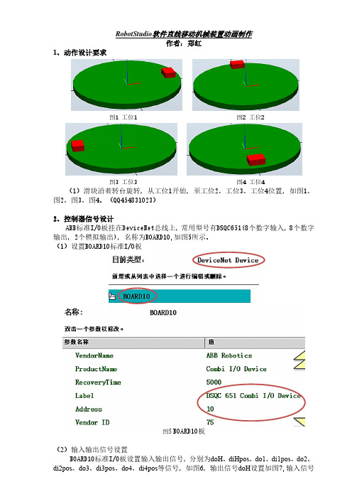
RobotStudio软件直线移动机械装置动画制作作者:郑红1、动作设计要求图1 工位1 图2 工位2图3 工位3 图4 工位4 (1)滑块沿着转台旋转,从工位1开始,至工位2、工位3、工位4位置,如图1、图2、图3、图4。
(QQ454831023)2、控制器信号设计ABB标准I/O板挂在DeviceNet总线上,常用型号有DSQC651(8个数字输入,8个数字输出,2个模拟输出),名称为BOARD10,如图5所示。
(1)设置BOARD10标准I/O板图5 BOARD10板(2)输入输出信号设置diHpos设置如图8。
图6 输入输出信号图7 输出信号doH图8 输入信号diHpos3、布局图94、“转台”机械装置设置(1)建模|创建机械装置,如图10;设定机械装置模型名称及类型,如图11;双击“链接”,打开对话框,如图12,按1-2-3-4-5顺序设置L1;如图13,按1-2-3-4顺序设置L2;设置好如图14。
图10图11 图12图13 图14(2)双击图11的“接点”,打开对话框,按1-2-3-4-5-6顺序设置J1,如图15;设置好后如图16;单击“编译机械装置”,如图17;单击“添加”,如图18;如图19,按1-2顺序设置好“姿态1”;如图20,按1-2顺序设置好“姿态2”;如图21,按1-2顺序设置好“姿态3”;如图22,按1-2顺序设置好“姿态4”;设置好后如图23。
图15 图16图17 图18 图19图20 图21图22 图23(3)如图24,单击“手动关节”激活按钮,然后用鼠标按住滑块,即可旋转移动滑块,并会显示旋转角度,如图25。
图24 图255、功能组件及信号设计(1)功能组件及信号设计图26 (2)I/O信号设置图27 (3)I/O信号连接图28(4)功能组件旋转动作设置图29 PoseMover姿态1动作设置图30 PoseMover-2姿态2动作设置图31 PoseMover-3姿态3动作设置图32 PoseMover-4姿态4动作设置6、工作站逻辑设计图33 工作站与功能组件信号连接7、程序设计PROC main()Reset do1;Reset do2;!控制器信号全部复位为0Reset do3;Reset do4;WaitTime 0.5;!暂停0.5(s)Set do1;!控制器信号do1置位为1WaitDI di1pos,1;WaitTime 3; !暂停3(s)Set do2; !控制器信号do2置位为1WaitDI di2pos,1;WaitTime 3; !暂停3(s)Set do3;!控制器信号do3置位为1WaitDI di3pos,1;WaitDI di4pos,1;WaitTime 3; !暂停3(s)Reset do1;Reset do2; !控制器信号全部复位为0Reset do3;Reset do4;WaitTime 0.5;ENDPROC8、播放动画单击“播放”按钮即可播放动画,如图34。

声明:本文档作为KUKA机器人编程规范指导,要求供应商按照相关定义编写程序结构和符号命名,具体逻辑和程序漏洞供应商自行检查,有发现问题请及时提出并统一修改,如有供应商编写程序直接抄写本文档造成的事故和其它原因对机器人造成的损害,责任由供应商承担。
机器人程序编写必须遵守当地国家和地区的标准,满足海斯坦普安全、工艺、电气规范等相关标准。
目录1.程序的存放: (4)1.1.\KRC\R1\MainProg文件里面放车型的主程序 (4)1.2.\KRC\R1\Application 存放焊接,抓放件,抓放抓手等应用子程序(如果车型较多可以按车型分开存放) (5)2.程序的调用 (5)3.轨迹程序命名: (6)3.1.焊接程序:WeldV339、WeldV466 (6)3.2.抓件程序:Pick###From xxx (6)3.3.放件程序:Drop###To xxx (6)3.4.服务程序: (6)3.5.常用点的起名: (7)3.6.Tool 的命名和使用: (7)3.7.Base 的命名和使用: (8)3.8.干涉区说明: (8)3.9.Seg 说明: (9)4.程序例子: (9)4.1.主程序:Cell (9)4.2.车型主程序:P01 (10)4.3.焊接子程序 (11)4.4.点焊包后台焊点计数,用于判断修模预警 (12)4.5.抓件程序 (12)4.6.修磨: (14)4.7.换帽: (15)4.8.服务位: (16)4.9.涂胶序(SCA): (17)4.10.螺柱焊 (19)4.11.激光焊接程序 (20)5.编写程序细节要求: (22)1.程序的存放:1.1.\KRC\R1\MainProg文件里面放车型的主程序例如:P01 车型1工作路径P02 车型2工作路径P201 焊枪1修磨P202 焊枪2修磨P211 焊枪1更换电极帽P212 焊枪2更换电极帽P221 枪维修程序1P222 枪维修程序2P141 维修抓手P161 维修换枪盘P250 抱闸测试P251 安全标定1.2.\KRC\R1\Application 存放焊接,抓放件,抓放抓手等应用子程序(如果车型较多可以按车型分开存放)2.程序的调用宏程序放在KRC/R1/TP/FUCTION里3.轨迹程序命名:3.1. 焊接程序:WeldV339、WeldV466V339、V466 为焊接零件号或焊接车型二次补焊程序:WeldV339_Respot、WeldV466_RespotV339_Respot、V466_Respot为焊接零件号或焊接车型二次补焊(例如抓手抓起空中补焊)3.2. 抓件程序:Pick###From xxx### 为工件号xxx 为工位号例如:PickPartV339FromOP50 从Op50 工位抓工件V339PickPartV466FromStand 从放置台抓工件V4663.3. 放件程序:Drop###To xxx### 为工件号xxx 为工位号例如:DropPartV339ToOP50 放件工件V339到OP50 工位DropPartV466ToStand 放件工件V466到放置台3.4. 服务程序:a)修磨程序TipDressGun1 焊枪1修磨TipDressGun2 焊枪2修磨b)换电极程序TipChangeGun1 焊枪1更换电极帽TipChangeGun2 焊枪2更换电极帽c)维修程序MaintGun1 焊枪1去维修MaintGun2 焊枪1去维修MaintGripV339 V339车型抓手去维修MaintGripV466 V466车型抓手去维修3.5. 常用点的起名:1)Home 位:Home2)机器人等待位:WaitPos(如果有多个等待可为WaitPos2等等)3)焊枪修磨位:Gun1TipDressPos4)焊枪更换电极帽位:Gun1TipChangePos (如果有多个焊枪多个修磨器可为Gun2TipChangePos 等等,该位置调试时候要考虑人为更换电极帽的方便性且避开线槽等电缆,如果空间允许尽量避开与其他机器人焊接干涉区)5)焊枪服务位:Gun1ServicePos 如果有多个焊枪可为Gun2ServicePos 等等,该位置调试时候要考虑维修的方便性,如果空间允许尽量避开与其他机器人干涉区)6)抓手服务位:GripV339ServicePos 如果有多个焊枪可为GripV466ServicePos 等等,该位置调试时候要考虑维修的方便性,如果空间允许尽量避开与其他机器人干涉区)7)抓件点:Pick###Pos1### 为工件号例如:PickPartV339Pos1(如果有多个位置为PickPartV339Pos2)8) 放件点:Drop###Pos1###为工件号例如:DropPartV339Pos1(如果有多个位置为DropPartV339Pos2)9) 焊点:严格按照提供的工艺文件来标注,每一个焊点调用一套参数;10) 过度点:Pxxxxxx 为0~999999(为阿拉伯数字,同一个程序中过渡点名字不可重复)3.6.Tool 的命名和使用:Tool1 Gun1 焊枪1Tool2 Gun2 焊枪2Tool3 GripV339WithoutPart 抓手V339不带件(不带件负载数据存放在这里)Tool4 GripV466WithoutPart 抓手V466不带件(不带件负载数据存放在这里)Tool7 GripV339WithPart 抓手V339带件(带件负载数据存放在这里)Tool8 GripV466WithPart 抓手V466带件(带件负载数据存放在这里)Tool16 ToolChange X:0,Y:0,Z:+100;A:0;B:0,C:0;Mess:20KG(换枪盘重量);其中Z为换枪盘厚度,+Z方向为垂直于法兰盘向外;换枪盘厚度重量可能不一样,需确认1、焊枪TCP 方向:(焊枪静臂电极帽)2、抓手TCP方向:(抓手定位销)3.7.Base 的命名和使用:BASE1 V339(车型或零件号名称)BASE2 V466(车型或零件号名称)BASE11 ExternalGun1 固定焊枪1BASE12 ExternalGun1 固定焊枪23.8.干涉区说明:退出干涉区点必须为精确到达,指令中去掉CONT注释在干涉区之前,且注释清楚和哪台机器人几号干涉区做什么任务例如:;EnterZone 1 with R3 WeldV339 进入干涉区1和R3机器人焊接V339车型干涉EnterZone(1);ExitZone2 With R3 DropPartV339ToUB30 退出干涉区1和R3机器人放件V339车型去UB30工位ExitZone(1)3.9.Seg 说明:注释在Seg之前,且注释清楚机器人要去做什么任务例如:;go to weld 去焊接WaitForSegment (1) 等待seg1EndSegment (1) 完成seg1;go to pickpartV339 去抓车型V339WaitForSegment (2) 等待seg24.程序例子:4.1. 主程序:Cell例如:INITBASISTECH INICHECK HOMEPTP HOME Vel= 100 % DEFAULTInitSignal() 初始化信号AUTOEXT INILOOPP00 (#EXT_PGNO,#PGNO_GET,DMY[],0 )SWITCH PGNO ; Select with ProgramnumberCASE 1P00 (#EXT_PGNO,#PGNO_ACKN,DMY[],0 ); Reset Progr.No.-Request P01 (); V339 //调用车型V339程序,后面需备注车型CASE 201P00 (#EXT_PGNO,#PGNO_ACKN,DMY[],0 ); Reset Progr.No.-RequestP201(); TipDressGun1 //调用修磨程序,后面需备注CASE 211P00 (#EXT_PGNO,#PGNO_ACKN,DMY[],0 ); Reset Progr.No.-RequestP211(); TipChangeGun1 //调用换帽程序,后面需备注CASE 221P00 (#EXT_PGNO,#PGNO_ACKN,DMY[],0 ); Reset Progr.No.-RequestP221(); MaintGun1 //调用焊枪维修程序,后面需备注DEFAULTP00 (#EXT_PGNO,#PGNO_FAULT,DMY[],0 )ENDSWITCHENDLOOPEND4.2. 车型主程序:P01DEF P01()INIPTP HOME Vel= 100 % DEFAULTToolChange.Couple Tool Number 1 配对1号工具,如果当前拿的不是1号工具则去切换工具PickPartV339FromFDL30 ( )WeldV339 ( )DropPartV339ToRack ( )PTP HOME Vel= 100 % DEFAULTTaskComplete ;工作完成Inisystem 初始化IF I[1]>400 THENIF EG_WEAR[1]>7.6 THENTipChangeGun1 ( )ELSETipDressGun1 ( )ENDIFENDIF 4.3. 焊接子程序DEF WeldV339INICheckForTool(1) 检测1号工具WaitForSegment (1) ;等待Seg1OUT 257 'O_WeldOn' State=TRUE 开水WaitFor IN 258 State=TURE 等待水流量正常PTP P1 Vel=100 % PDAT1 Tool[2]:Gripper_CD101 Base[1]:EX_GUN1 extTCPEnterZone (1) ;等待进入干涉区1PTP P3 CONT Vel=100 % PDAT4 Tool[2]:Gripper_CD101 Base[1]:EX_GUN1 extTCP OUT 23 State=TURE 机器人停止Wait For IN 23 State=False 等待取消暂停OUT 23 State=False 机器人停止取消 PTP SG2 Vel=100 % PDAT7 ProgNr=1 ServoGun=1 Cont=CLS OPN Part=1.9 mm Force=2.2 kN ApproxDist=5 mm SpotOffset=0 mm Tool[2]:Grip_S401Base[1]:EX_GUN1 extTCP ;焊点编号为SE2,焊点后退距离调用子程序 焊点数量超过400且修磨量大于7.6时,调用换帽程序;焊点数量超过400且修磨量不大于7.6时,调用修磨程序;为5,焊点偏移值为0,整个焊接程序中选用的工具号需要一致,并且使用正确的负载数据PTP P12 CONT Vel=100 % PDAT15 Tool[2]:Gripper_CD101 Base[2]:GUN1_CD101/Mra2 extTCPExitZone(1) ;退出干涉区1EndSegment (1) ;结束Seg1END*************************************************************************** 4.4. 点焊包后台焊点计数,用于判断修模预警GLOBAL DEF EG_POST_SPOT ();----------------------------------------;post spot handling;----------------------------------------IF EG_EXTAX_ACTIVE==1 THENCOUNT1=COUNT1+1 ;GUN1 焊点计数ENDIFIF EG_EXTAX_ACTIVE==2 THENCOUNT2=COUNT2+1 ;GUN2 焊点计数ENDIFIF EG_EXTAX_ACTIVE==3 THENCOUNT3=COUNT3+1 ;GUN3 焊点计数ENDIFIF EG_EXTAX_ACTIVE==4 THENCOUNT4=COUNT4+1 ;GUN4 焊点计数ENDIF*************************************************************************** 4.5. 抓件程序DEF PickPartV339FromL010FX01()INIPTP HOME Vel= 100 % DEFAULTCheckForTool(2) ;检测2号工具号WaitForSegment (1) ;等待Seg1允许进入No_Part_Present (2,2) ;检测2号抓手2个工件传感器都无工件感应Release_Part (2,1,TRUE);打开2号工具的夹爪(2号工具,1组气缸,TRUE检测打开到位) EnterZone(1) ;请求进入1号干涉区PTP P4 CONT Vel=100 % PDAT2 Tool[3]:Grip_S401 Base[0]PTP P2 CONT Vel=100 % PDAT7 Tool[3]:Grip_S401 Base[0];Before PICK PART POSTION ;备注抓件前一个点,并且需要使用直线指令LIN P8 CONT Vel=2 m/s CPDAT5 Tool[3]:Grip_S401 Base[0];PICK PART V339 Pos ;备注抓件点,并且需要使用直线指令精准到达LIN P11 Vel=1 m/s CPDAT6 Tool[3]:Grip_S401 Base[0]Part_Present (2,1) ;检测2号抓手,1组传感器感应到Grip_Part(2,1,TRUE) ;夹紧(2号抓手,第一组阀,检测夹紧到位)EndSegment (1)WaitForSegment (2)LIN P12 Vel=1 m/s CPDAT7 Tool[3]:Grip_S401 Base[0]PTP P7 CONT Vel=100 % PDAT4 Tool[3]:Grip_S401 Base[0]PTP P14 CONT Vel=100 % PDAT10 Tool[3]:Grip_S401 Base[0]PTP P15 CONT Vel=100 % PDAT11 Tool[3]:Grip_S401 Base[0]PTP P10 Vel=100 % PDAT8 Tool[3]:Grip_S401 Base[0]EndSegment (2) ;结束Seg2ExitZone(1) ;退出干涉区1END***************************************************************************4.6. 修磨:DEF tipdress()INIOUT 257 O_startwater ' State= FALSE ;修模前关水PTP HOME Vel= 100 % DEFAULTPTP P1 CONT Vel=100 % PDAT1 Tool[1]:Gun1 Base[0]PTP P4 CONT Vel=100 % PDAT4 Tool[1]:GUN1 Base[0]PTP p5 CONT Vel=100 % PDAT22 Tool[1]:GUN1 Base[0]PTP p6 CONT Vel=100 % PDAT23 Tool[1]:GUN1 Base[0]PTP p18 CONT Vel=100 % PDAT28 Tool[1]:Gun1 Base[0]OUT 258 'O_STARTTIPDRESSER ' State= TRUE ;修模机旋转OUT 314 'O_IFNOWELD ' State= TRUE ;无电模式开启PTP SG0000006 Vel=100 % PDAT30 TipDress ProgNr=1 ServoGun=1 Part=7.5 mm Force=0.5 kN ApproxDist=5 mm SpotOffset=0 mm Tool[1]:Gun1 Base[0]OUT 258'O_STARTTIPDRESSER ' State= FALSE ;修模机旋转停止PTP p7 CONT Vel=100 % PDAT21 Tool[1]:GUN1 Base[0]PTP p8 Vel=100 % PDAT11 Tool[1]:GUN1 Base[0]PTP p16 Vel=100 % PDAT26 Tool[1]:GUN1 Base[0]PTP INIT ServoGun=1 Same ;旧电极帽修模补偿计算PTP p17 Vel=100 % PDAT27 Tool[1]:GUN1 Base[0]PTP p9 CONT Vel=100 % PDAT20 Tool[1]:GUN1 Base[0]PTP p10 CONT Vel=100 % PDAT19 Tool[1]:GUN1 Base[0]PTP p19 CONT Vel=100 % PDAT31 Tool[1]:Gun1 Base[0]PTP p1 CONT Vel=100 % PDAT32 Tool[1]:Gun1 Base[0]PTP HOME Vel=100 % DEFAULTweld_count=0 ;焊点计数清零OUT 314 'O_IFNOWELD ' State= FALSE 无电模式关闭OUT 257 O_startwater ' State= TURE 开水END*************************************************************************** 4.7. 换帽:DEF TipChange_gun1()INIOUT 257 'O_startwater' State=FALSE ;换帽关水OUT 27 State=TRUE ;进入换帽区域PTP HOME Vel= 100 % DEFAULTPTP P1 CONT Vel=100 % PDAT1 Tool[1]:Gun1 Base[0]PTP P4 CONT Vel=100 % PDAT4 Tool[1]:GUN1 Base[0]PTP p5 CONT Vel=100 % PDAT22 Tool[1]:GUN1 Base[0];TipChange PosPTP p6 Vel=100 % PDAT23 Tool[1]:Gun1 Base[0]Halt ;wait for change tip ;换帽位置OUT 26 State=TUREWait for $IN[26] ;等待换帽确认$OUT[26]=FALSE ;换帽位置关闭PTP p18 CONT Vel=100 % PDAT28 Tool[1]:Gun1 Base[0]PTP p8 Vel=100 % PDAT11 Tool[1]:GUN1 Base[0]PTP p16 Vel=100 % PDAT26 Tool[1]:GUN1 Base[0]PTP INIT ServoGun=1 New ;旧电极帽修模补偿计算PTP p17 Vel=100 % PDAT27 Tool[1]:GUN1 Base[0]PTP p9 CONT Vel=100 % PDAT20 Tool[1]:GUN1 Base[0]PTP p10 CONT Vel=100 % PDAT19 Tool[1]:GUN1 Base[0]PTP p19 CONT Vel=100 % PDAT31 Tool[1]:Gun1 Base[0]PTP p1 CONT Vel=100 % PDAT32 Tool[1]:Gun1 Base[0]PTP HOME Vel=100 % DEFAULTOUT 27 State=FALSEEND*************************************************************************** 4.8. 服务位:DEF Server_gun1()INIOUT 257 'O_startwater' State=FALSE 关水OUT 27 State=TRUE ;进入维修区域PTP HOME Vel= 100 % DEFAULTPTP P1 CONT Vel=100 % PDAT1 Tool[1]:Gun1 Base[0]PTP P4 CONT Vel=100 % PDAT4 Tool[1]:GUN1 Base[0]PTP p5 CONT Vel=100 % PDAT22 Tool[1]:GUN1 Base[0];Server PosPTP p6 Vel=100 % PDAT23 Tool[1]:Gun1 Base[0]Halt ;wait for change tip ;服务位置OUT 22 State=TUREWait for $IN[22] ;等待维修确认$OUT[22]=FALSE ;维修位置关闭PTP p18 CONT Vel=100 % PDAT28 Tool[1]:Gun1 Base[0]PTP p8 Vel=100 % PDAT11 Tool[1]:GUN1 Base[0]PTP p16 Vel=100 % PDAT26 Tool[1]:GUN1 Base[0]PTP INIT ServoGun=1 New ;旧电极帽修模补偿计算PTP p17 Vel=100 % PDAT27 Tool[1]:GUN1 Base[0]PTP p9 CONT Vel=100 % PDAT20 Tool[1]:GUN1 Base[0]PTP p10 CONT Vel=100 % PDAT19 Tool[1]:GUN1 Base[0]PTP p19 CONT Vel=100 % PDAT31 Tool[1]:Gun1 Base[0]PTP p1 CONT Vel=100 % PDAT32 Tool[1]:Gun1 Base[0]PTP HOME Vel=100 % DEFAULTOUT 27 State=FALSEEND***************************************************************************4.9. 涂胶序(SCA):DEF GlueV339L010( )INIPTP HOME Vel=100 % DEFAULTIF NOT $IN[629] THEN IN629_Heat readyPULSE 607 'OUT607_Retrigger Heat' State=TRUE Time=0.2 secPULSE 608 'OUT608_Retrigger Pump' State=TRUE Time=0.2 secWAIT FOR ( IN 629 ' IN629_Heat ready ' )ENDIFIF $IN[602] THEN IN602_purge requestPurge COMPLETE System=1 With Air=NO Component=A Gun=1ENDIFWAIT FOR ( IN 4 'IN4_DRY_RUN_NO_PART' ) OR ( IN 593 'IN593_General fault' AND IN 597 'IN597_Fault System' AND IN 600 'IN600_Ready to oper.' ) 等待空循环,或胶机状态正常如果加热未准备好则输出加热指令 如果有请求冲洗则输出冲洗胶机状态设定Initialize And Start System 1 Fill Doser=Yes Set Program No=1 Param No=1 BeadData=1LIN P56 CONT Vel=0.5 m/s CPDAT50 Tool[7]:GRIPS21WITHPART Base[22]:GLUE GUN extTCP ;Glue Line 1LIN P22 Vel=0.2 m/s CPDAT18 GlueOn Distance=0 mm Gun=1 Check PrePressure=YesTool[7]:GRIPS21WITHPART Base[22]:GLUE GUN extTCP 开枪LIN P2 CONT Vel=0.02 m/s CPDAT1 Tool[7]:GRIPS21WITHPART Base[22]:GLUE GUN extTCPLIN P45 Vel=0.15 m/s CPDAT40 GlueOff Distance=5 mm End Measurement=No Change Doser=No Tool[7]:GRIPS21WITHPART Base[22]:GLUE GUN extTCP 关枪;Glue Line 2LIN P24 Vel=0.2 m/s CPDAT20 GlueOn Distance=0 mm Gun=1 Check PrePressure=YesTool[7]:GRIPS21WITHPART Base[22]:GLUE GUN extTCP 开枪LIN P3 CONT Vel=0.02 m/s CPDAT2 Tool[7]:GRIPS21WITHPART Base[22]:GLUE GUN extTCPLIN P25 Vel=0.15 m/s CPDAT21 GlueOff Distance=5 mm End Measurement=No Change Doser=No Tool[7]:GRIPS21WITHPART Base[22]:GLUE GUN extTCP 关枪PTP P12 CONT Vel=100 % PDAT2 Tool[7]:GRIPS21WITHPART Base[22]:GLUE GUN extTCP PTP HOME Vel=100 % DEFAULTIF NOT($IN[4] OR $OUT[3])T1 THENOUT 593 'OUT593_Start' State=FALSE WAIT Time=0.2 secOUT 604 'OUT604_Cycle end' State=TRUE WAIT Time=0.2 secOUT 604 'OUT604_Cycle end' State=FALSE WAIT FOR ( IN 599 'IN599_Application OK' ) ENDI 如果不在空循环或T1模式,则输出涂胶循环结束等指令,等待胶机 涂胶OK信号反馈4.10. 螺柱焊DEF Stud_S700_11_01()INIPTP P005 Vel=100 % P_OLP14 Tool[15] Base[27]:S700_60PTP P010 CONT Vel=100 % P_OLP2 Tool[15]" " Base[27]" "PTP P015 CONT Vel=100 % P_OLP3 Tool[15]" " Base[27]" "PTP P020 CONT Vel=100 % P_OLP4 Tool[15]" " Base[27]" "PTP Stud133020 CONT Vel=100 % P_OLP5 Tool[15]" " Base[27]" " StudWeld(1,1);螺柱焊枪1,焊接程序1PTP Stud133018 CONT Vel=100 % P_OLP6 Tool[15]" " Base[27]" " StudWeld(1,2) ;螺柱焊枪1,焊接程序2PTP Stud133096 CONT Vel=100 % P_OLP7 Tool[15]" " Base[27]" " StudWeld(1,3) ;螺柱焊枪1,焊接程序3PTP Stud133009 CONT Vel=100 % P_OLP8 Tool[15]" " Base[27]" " StudWeld(1,4) ;螺柱焊枪1,焊接程序4PTP P025 CONT Vel=100 % P_OLP9 Tool[15]" " Base[27]" "PTP Stud132054 CONT Vel=100 % P_OLP10 Tool[15]" " Base[27]" " StudWeld(1,5) ;螺柱焊枪1,焊接程序5PTP P030 CONT Vel=100 % P_OLP11 Tool[15]" " Base[27]" "PTP P035 CONT Vel=100 % P_OLP12 Tool[15]" " Base[27]" "PTP P040 CONT Vel=100 % P_OLP13 Tool[15]" " Base[27]" ";#START_TRAILERPTP HOME Vel= 100 % DEFAULTEND4.11. 激光焊接程序DEF AS26_SidePlateWd_NEW0211( )INIPTP HOME Vel=20 % DEFAULTLaser_init(1); 1号光路信号初始化PTP P31 CONT Vel=30 % PDAT22 Tool[1]:Scanner Base[0]PTP P27 Vel=30 % PDAT18 Tool[1]:Scanner Base[0]LaserON(1);激光开光(程序号1)LIN ADR1_1 Vel=0.1 m/s CPDAT1 Tool[1]:Scanner Base[1]:ScanlabWeldBase1 LIN ADR1_2 Vel=0.1 m/s CPDAT5 Tool[1]:Scanner Base[1]:ScanlabWeldBase1 LaserOff();关激光PTP P28 Vel=30 % PDAT19 Tool[1]:Scanner Base[0]LaserON(2);激光开光(程序号1)LIN ADR2_1 Vel=0.1 m/s CPDAT2 Tool[1]:ScannerBase[2]:ScanlabWeldBase2 LIN ADR2_2 Vel=0.1 m/s CPDAT8 Tool[1]:Scanner ase[2]:ScanlabWeldBase2 LaserOff();关激光PTP P6 CONT Vel=30 % PDAT5 Tool[1]:Scanner Base[0]OUT 1441 'finish seg2' State=TRUEPTP P32 CONT Vel=30 % PDAT23 Tool[1]:Scanner Base[0]LaserEND();激光焊接结束,安全信号锁定PTP HOME Vel=30 % DEFAULTInitSignal()4.12无焊接电流程序检查W AIT FOR NOT($POWER_FAIL)TORQUE_MONITORING();FOLD BACKUPMANAGER PLCIF BM_ENABLED THENBM_OUTPUTSIGNAL = BM_OUTPUTV ALUEENDIF;ENDFOLD (BACKUPMANAGER PLC);FOLD USER PLC;Make your modifications hereIF ($IN[7]==TRUE)OR($IN[4]==TRUE) THEN 如果空循环或者不出电流$OUT[5]=TRUE 空运行信号输出$LOOP_MSG[]=" "ELSE$OUT[5]=FALSE 空运行信号关闭$LOOP_MSG[]=" "ENDIF;ENDFOLD (USER PLC)ENDLOOP5.编写程序细节要求:1.在修模换帽应用上,焊点由机器人自己计数实现功能2.每一个焊点调用一套焊接参数,焊点编号不能重复3.自动区域开门请求进入信号PLC发给机器人,机器人收到该信号后完成当前轨迹小段程序后,在不影响工艺的情况下停止,并反馈停止信号给PLC,PLC才可解锁开门。

abb搬运码垛程序目录:1、简介2、系统硬件2.12.2 码垛工作台3、系统软件3.1 ABB RobotStudio3.2 码垛程序4、编程步骤4.1 创建工作目录4.2 连接4.3 创建码垛程序4.4 算法设计4.5 编写程序代码4.6 调试程序5、运行程序6、附件1、简介:本文档将介绍ABB在搬运和码垛任务中的程序开发方法。
通过使用ABB RobotStudio软件,结合和码垛工作台的硬件设备,可以实现自动化的搬运码垛操作。
2、系统硬件:2.1 :- 品牌:ABB- 型号:- 功能:搬运和码垛任务2.2 码垛工作台:- 品牌:- 型号:- 功能:提供码垛操作的工作平台,包括传送带、传感器等附件3、系统软件:3.1 ABB RobotStudio:- 版本:- 功能:用于程序的开发、调试和仿真3.2 码垛程序:- 开发环境:ABB RobotStudio- 功能:实现在搬运和码垛任务中的运动控制和路径规划4、编程步骤:4.1 创建工作目录:- 在ABB RobotStudio中创建新的工作目录,用于存放码垛程序和相关文件4.2 连接:- 使用ABB RobotStudio中的连接功能,将开发环境与实际的进行连接4.3 创建码垛程序:- 在工作目录中创建新的码垛程序- 设定的起始位置和姿态- 设置码垛工作台的位置和尺寸参数4.4 算法设计:- 根据具体的码垛任务需求,设计相应的算法- 包括货物识别、路径规划、运动控制等方面的算法设计4.5 编写程序代码:- 使用ABB RobotStudio提供的编程语言,编写的运动控制和路径规划代码- 根据算法设计的结果,将相应的命令和参数写入程序4.6 调试程序:- 在ABB RobotStudio中进行程序的调试和仿真- 检查程序的正确性和稳定性,进行必要的修改和优化5、运行程序:- 将调试好的程序至实际的系统- 配置工作环境,包括码垛工作台的准备、传感器的调整等 - 运行程序,观察的运动和码垛任务的执行情况6、附件:本文档涉及的附件包括:- ABB RobotStudio软件安装包- 和码垛工作台的规格参数文档 - 码垛程序源代码文件- 算法设计文档和相关说明7、法律名词及注释:(待补充)。
robotframework介绍Robot Framework介绍1. 什么是Robot Framework?Robot Framework是一个开源的自动化测试框架。
它提供了一种简单而灵活的方式来编写测试用例,并且支持关键字驱动测试(Keyword Driven Testing)。
它使用简洁的语法和易于理解的表格格式,使得非技术人员也能够编写自动化测试用例。
2. Robot Framework的特点2.1 关键字驱动Robot Framework允许使用关键字来描述测试步骤。
这些关键字可以是已编写好的关键字库,也可以是用户自定义的关键字。
通过使用关键字,我们可以将测试过程的细节隐藏起来,使得测试用例更加清晰和易于阅读。
2.2 多种测试库支持Robot Framework支持多种测试库,包括Selenium、Appium、Requests等。
这使得Robot Framework可以用于不同类型的应用程序和系统的测试。
2.3 插件机制Robot Framework支持插件机制,允许用户定制自己的扩展库,以满足特定的测试需求。
这个机制也使得Robot Framework具有良好的可扩展性。
2.4 灵活的结果输出Robot Framework可以以多种形式输出测试结果,包括、XML和日志文件。
这些输出格式可以帮助开发人员和测试人员快速定位和解决问题。
2.5 易于集成Robot Framework可以很容易地与其他工具集成,如Jenkins和Git。
这样可以方便地进行持续集成和版本控制。
3. Robot Framework的使用场景Robot Framework适用于各种类型的自动化测试,包括Web应用程序、移动应用程序、API测试等。
它还可以用于功能测试、回归测试和端到端测试。
4. Robot Framework的安装和使用要安装Robot Framework,可以使用pip命令进行安装:pip install robotframework安装完成后,可以使用以下命令运行测试用例:robot testcases.robot其中,`testcases.robot`是测试用例文件的路径。
ABB 机器人经典小程序介绍本文档集中收集了一批ABB 机器人编程的小程序,这些小程序在很多场合下可能对对于大家的编程有益,能够解决大家在各个场合下的应用,这些程序中包含了各种各样的函数计算,圆心寻找,以及各中函数计算。
如果大家赶兴趣,可以在百度文库付费文档中找到“ABB机器人编程经典小程序.pdf”,该文档中将各种小程序的函数进行了详细的介绍。
下面是提供的程序的主要用途和功能的介绍。
1. UTL_alignToPointAligns the robot around tcp to an orientation of a known point.2. UTL_calcOrg Afunction which calculates the origin from two points on x-axis and one point on y-axis.3. UTL_defObjDefinition of object frame in a work object from two points on x-axis and one point on y-axis.4. call_routineIndirect call via reg.5. UTL_eulerFrPointTranslates orientation of as point to euler angles.6. UTL_eulerFrToolTranslates orientation of a tool to euler angles.7. UTL_eulerToObjDefinition of orientation of an object frame from three euler angles.8. UTL_ eulerToPointDefinition of orientation of a point from three euler angles.9. UTL_ eulerToToolDefinition of orientation of a tool from three euler angles.10. UTL_eulerToUsrDefinition of orientation of user frame from three euler angles.11. UTL_mirSetOffset/UTL_mirSetPlaneDefinition of mirror planes, parallel with main planes or arbitrary.12. UTL_quatFrEulerTranslation from euler angles to quaternion values.13. UTL_quatToEulerTranslation from quaternion values to euler angles.14. UTL_recalcPointRecalculates a point corresponding to the difference between two workobjects or thedefference between two tools.15. UTL_scalFunction which returns the scalar product of two vectors.16. UTL_toolDefFixDefinition of a room fixed (stationary) tool.17. UTL_toolDefPointDefinition of a tool with the help of a predefined reference point.18. UTL_toolDefWobjDefinition of a tool with the help of a predefined work object.19. UTL_toolUpdateThe tool value (tcp) is updated with the help of a predefined reference point. See alsoUTL_toolAutoUpd below.20. UTL_wobjOriUpdThe orientation of an object frame of a work object is updated by jogging the robot to a correctorientation.21. UTL_cirRadiFunction to calculate the radius of a circle given by three points on the circumference.22. UTL_cirCentrFunction to calculate the centre of a circle given by three points on the circumference.23. UTL_MoveCCRoutine which will move the robot in a complete circle, where thestart point and the centre point is given24.UTL_DefDFrameFunction which will be similar to the installed DefDFrame, but give a better accuracy.25.UTL_toolAutoUpdProcedure to update a tool with the difference between two given points. See alsoUTL_toolUpdate26.UTL_moveTurnProcedure to perform a simple search movement, which breaks the search movement and movesthe robot to an other position, when an input is activated.27.UTL_wobjAdjustProcedure to adjust the orientation of a workobject, so that the z-axis will point in a new wanteddirection.28. UTL_toolFixUpdThe tool value (tcp) of a stationary, room fixed tool is updated with the help of a predefinedreference point.29. UTL_baseFrAdjThis procedure may be used to adjust the base frame of a coordinated manipulator, e.g. asingle rotational axis, so that the z-axis of the coordinated work object, user part, will be inline with the rotational axis.30. UTL_ imdPosThis function will calculate an intermediate point on the line between two points and on aspecified distance from the first point.31. UTL_recalcPFixProcedure: Recalculates a point expressed with one tool and one workobject,to be expressed with another roomfixed tool and in another workobject.232. UTL_distThe function will calculate the distance between two robtarget positions.33. UTL_orDifThe function will calculate the rotation angle in degrees between the orientations of tworobtarget positions.34. UTL_checkPointProcedure: Check if the distance between the current position of the robot andthe given point is within a fixed value. If not, the robot is moved to the point with a MoveJinstruction. The allowed difference is 70 mm resp. 30 degrees for orientation.35. f_ToolCalcThe function will take two tooldata, e.g. the tooldata values for two pins, one short and onelong, and then calculate a new tool orientation where the z axis will point from the shorter tipto the longer tip. It will also calculate a new tcp value, based on the length of the longer pinand a new tool.31 UTL_alignToPointGeneralThe routine may be used to reorient the robot and its tool in the current position, so that the orientation ofthe tool will coincide with the orientation of a given point, e.g. p120.Please observe, that before this routine is used, be sure that the used tool, e.g. grip, and work object, e.g.wobj1, are "active" (check in jog window).Working sequence1. Execute the routine UTL_alignToPoint as described below:Choose the test window by pressing the function button Test. Choose the menu Special/4 Move PP toRoutine.Search for the routine UTL_alignToPoint and mark this. Press OK.Then press the function button Start to start the execution.2. Now you are asked to give the name of the point whose orientation you want to use, e.g. p120, and thename of the tool and work object you are using, e.g. grip and wobj1. These names should be put intothe marked instruction atp pnt, u_tool, u_wobj;Press the right arrow, so that pnt is marked, press enter. Then choose p120 and press Next. Thenchoose grip and press Next. Then choose wobj1 and press OK.Check that the instruction now will look like:atp p120, grip, wobj1;3 Press Start and the robot will reorient to the desired orientation with a slow speed.42 UTL_calcOrg()GeneralThis function is suitable to use in combination e.g. with the function DefDFrame at the calculation of aprogram displacement after a search operation. Suppose, for instance, that you want to localize a box withthree search movements, search1 - search3, as shown in the figure below:With the box in its original position, three searches will give the points p1 - p3. After a displacement thesame search movements will give the three points p4 - p6. Now it's not possible to use directly the functionDefDFrame with the points p1 - p6 to get the displacement frame, since p1 and p4 doesn't correspond to thesame point on the box, which it should be. Instead of these two points, a better choice would be the corner Ato be used as the argument OldP1 and NewP1.The location of the corner A may be calculated from the points p1 - p3 with the function UTL_calcOrg. Inthe displaced position the corner is calculated from the points p4 - p6. The UTL_calcOrg routine accordinglycalculates the point of intersection between the line through p1 and p2 and a line through p3 perpendicularto the first line. This function takes as input-arguments three robtargets, and returns an other robtarget. Working sequenceTo achieve a search operation of an object as described above, please follow the steps below:1. It is supposed that the points p1 - p3 are known.Then make a search routine with three searches according to the figure above, to get the points p4 - p6,e.g. as below:MoveL *, v200, z10, tool1; (start point)SearchL *, sensor1, p4, v50, tool1; (p4=search point)MoveL *, v200, z10, tool1; (start point)SearchL *, sensor1, p5, v50, tool1; (p5=search point)MoveL *, v200, z10, tool1; (start point)SearchL *, sensor1, p6, v50, tool; (p6=search point)2. Calculate the corner A with the function UTL_calcOrg, first in the original position, p7, and then in thedisplaced position, p8.p7 := UTL_calcOrg(p1, p2, p3);p8 := UTL_calcOrg(p4, p5, p6);3. Calculate the displacement frame, frame1, and make it active:frame1 := DefDFrame(p7, p2, p3, p8, p5, p6);PDispSet frame1;563 UTL_defObjGeneralThe routine may be used to define the object frame of a moveable work object, i.e. a work object which iscoordinated to a manipulator, e.g. a turn table.Of course, the routine may be used to define the object frame also of a normal work object.Working sequence1. Suppose that the work object to be defined is wobj1. This may be moveable or fixed. Check that theobject frame (oframe) is cleared, i.e. x=0, y=0, z=0, q1=1, q2=0, q3=0, q4=0.2. Execute the routine UTL_defObj as described below:Choose the test window by pressing the function button Test. Choose the menu Special/4 Move PP toRoutine.Search for the routine UTL_defObj and mark this. Press OK.Then press the function button Start to start the execution.3. Now you are asked to activate the tool and work object. This is done by shifting to the jogwindow, andthere choose a known tool with a tip, and the work object wobj1. Then press Start.ONLY RW2.0:4. You are asked to decide where to place the origin. This might be placed in three different points, in p1,in p2, or so that the y-axis is going through p3.Press the desired function button.5 Jog the robot to the first position p1, placed on the x-axis, and press Start.6. Jog the robot to the second position p2, placed in the positive direction on the x-axis, and press Start.7. Jog the robot to the third position p3, placed in the positive direction in the xy-plane, and press Start.8. - 9. -ONLY M94A:4. Jog the robot to the first position p1, placed where you want the origin to be located.5. Mark the argument p1 in the instructioncal_obj p1, p2, p3, u_wobj;Press ModPos.6. Jog the robot to the second position p2, placed in the positive direction on the x-axis.7. Mark the argument p2 in the instructioncal_obj p1, p2, p3, u_wobj;Press ModPos.8. Jog the robot to the third position p3, placed in the positive direction in the xy-plane.9. Mark the argument p3 in the instructioncal_obj p1, p2, p3, u_wobj;Press ModPos.7BOTH RW2.0 AND M94A:10. Mark the argument u_wobj in the instructioncal_obj p1, p2, p3, u_wobj;Change it to wobj1.11. Press Start again, and the work object will be updated.84 call_routineGeneralThis routine may be used to make so called indirect program call, i.e. what in S3 is known as program callvia register.Working sequence1. Create the routines, which you want to make indirect calls to and give them appropriate names likeroutine1, routine2, routine3 etc.2. Open the routine call_routine under View/Routines. You may have to choose "Routine/In System"before.3. Mark the branchCase 1:<SMT>and press the function button Copy.4. Make as many Paste as you have routines you want to call.5. Mark <SMT> in the first branch and change this to the routine1, by choosing ProcCall in theinstructions pick list, and then choose routine1 in the routine list.6. Repeat item 5 for the other branches and put in routine2 etc.7. When you want to make an indirect routine call in your program, you choose ProcCall and markcall_routine and press Enter.Now you will have the choice to give a numeric argument, which might be a numeric constant like 2.This means that routine2 should be called. You may also choose a register or an other numeric variablelike reg2 as an argument. This means that the routine will be called, which corresponds to the value inreg2. If the value is 3, the routine3 will be called etc.95 UTL_eulerFrPointGeneralThe routine may be used to read the orientation for a point expressed in three angle values, for rotationaround the new x-axis, in this order.Working sequence1. Execute the routine UTL_eulerFrPoint as described below:Choose the test window by pressing the function button Test. Choose the menu Special/4 Move PP toRoutine.Search for the routine UTL_eulerFrPoint and mark this. Press OK.Then press the function button Start to start the execution.2. Now you are asked to give the name of the point you want to read, e.g. p30. This name should be putinto the marked instructionefp pnt;Press the right arrow, so that pnt is marked, press enter. Then choose p30 and press OK.Check that the instruction now will look like:efp p30;3. Press Start again.4. Now the corresponding values for z-angle, y-angle and x-angle are shown on the display, given indegrees.5. You are asked if you want to proceed with more points or not.106 UTL_eulerFrToolGeneralThe routine may be used to read the orientation for a tool expressed in three angle values, for rotation aroundthe z-axis, around the new y-axis and around the new x-axis, in this order.Working sequence1. Execute the routine UTL_eulerFrTool as described below:Choose the test window by pressing the function button Test. Choose the menu Special/4 Move PP toRoutine.Search for the routine UTL_eulerFrTool and mark this. Press OK.Then press the function button Start to start the execution.2. Now you are asked to give the name of the tool you want to read, e.g. grip. This name should be putinto the marked instructioneft u_tool;Press the right arrow, so that u_tool is marked, press enter. Then choose grip and press OK.Check that the instruction now will look like:eft grip;3. Press Start again.4. Now the corresponding values for z-angle, y-angle and x-angle are shown on the display, given indegrees.5. Press OK to finish.117 UTL_eulerToObjGeneralThe routine may be used to define the orientation of the object frame (oframe) of a work object by givingthree angle values, for rotation around the z-axis, around the new y-axis and around the new x-axis, in thisorder.Working sequence1. Execute the routine ULT_eulerToObj as described below:Choose the test window by pressing the function button Test. Choose the menu Special/4 Move PP toRoutine.Search for the routine UTL_eulerToObj and mark this. Press OK.Then press the function button Start to start the execution.2. Now you are asked to give the name of the work object you want to update, e.g. wobj10. This nameshould be put into the marked instructionetwo u_wobj;Press the right arrow, so that u_wobj is marked, press enter. Then choose wobj10 and press OK.Check that the instruction now will look like:etwo wobj10;3. Press Start again.4. Now you are asked to put in the values for z-angle, y-angle and x-angle.These are given in degrees.5. Press Start again, and the orientation in wobj10 will be updated.128 UTL_eulerToPointGeneralThe routine may be used to change the orientation for a point by giving three angle values, for rotationaround the z-axis, around the new y-axis and around the new x-axis, in this order.Working sequence1. Execute the routine UTL_eulerToPoint as described below:Choose the test window by pressing the function button Test. Choose the menu Special/4 Move PP toRoutine.Search for the routine UTL_eulerToPoint and mark this. Press OK.Then press the function button Start to start the execution.2. Now you are asked to give the name of the point you want to update, e.g. p30. (Please observe that thispoint must be a VAR or PERS, not a CONST)This name should be put into the marked instructionetp pv;Press the right arrow, so that pv is marked, press enter. Then choose p30 and press OK.Check that the instruction now will look like:etp p30;3. Press Start again.4. Now you are asked to put in the values for z-angle, y-angle and x-angle.These are given in degrees.5. Press Start again, and the orientation in p30 will be updated.139 UTL_eulerToToolGeneralThe routine may be used to change the orientation for a tool by giving three angle values, for rotation aroundthe z-axis, around the new y-axis and around the new x-axis, in this order.Working sequence1. Execute the routine UTL_eulerToTool as described below:Choose the test window by pressing the function button Test. Choose the menu Special/4 Move PP toRoutine.Search for the routine UTL_eulerToTool and mark this. Press OK.Then press the function button Start to start the execution.2. Now you are asked to give the name of the tool you want to updated, e.g. grip. This name should be putinto the marked instructionett u_tool;Press the right arrow, so that u_tool is marked, press enter. Then choose grip and press OK.Check that the instruction now will look like:ett grip;3. Press Start again.4. Now you are asked to put in the values for z-angle, y-angle and x-angle.These are given in degrees.5. Press Start again, and the orientation in grip will be updated.1410 UTL_eulerToUsrGeneralThe routine may be used to define the orientation of the user frame (uframe) of a work object by giving threeangle values, for rotation around the z-axis, around the new y-axis and around the new x-axis, in this order. Working sequence1. Execute the routine UTL_eulerToUsr as described below:Choose the test window by pressing the function button Test. Choose the menu Special/4 Move PP toRoutine.Search for the routine UTL_eulerToUsr and mark this. Press OK.Then press the function button Start to start the execution.2. Now you are asked to give the name of the work object you want to update, e.g. wobj10. This nameshould be put into the marked instructionetwu u_wobj;Press the right arrow, so that u_wobj is marked, press enter. Then choose wobj10 and press OK.Check that the instruction now will look like:etwu wobj10;3. Press Start again.4. Now you are asked to put in the values for z-angle, y-angle and x-angle.These are given in degrees.5. Press Start again, and the orientation in wobj10 will be updated.1511 UTL_mirSetOffset, UTL_mirSetPlaneGeneralTo facilitate the definitions of mirror planes, a some work objects for mirroring, MIRYZ and MIRXZ, seebelow, have been predefined. These may be used when you want to mirror in the main planes of the worldcoordinate system. Just choose e.g. MIRYZ etc. in the mirror dialog in the line for mirror frame.More over, some routines, UTL_mirSetOffset and UTL_mirSetPlane, may be used for automatic definitionof offset or to define an arbitrary mirror plane.These routines then may be used instead of the built in function under Special/Define Coord in the datawindow.Predefined work objects for mirror planes.In the system module utility two work objects are predefined for mirroring:miryz and mirxz.miryz is to be used when mirroring in a plane parallel to the yz-plane of the world coordinate system, andmirxz when mirroring in a plane parallel with the xz-plane of the world coordinate system. When mirroringin the xy-plane the wobj0 might be used.Mirroring with predefined work objects.In the dialog for mirroring, some of the work objects mentioned above, are given, resulting in the mirroringin the corresponding plane. See example below, where mirroring is done using mirxz:Automatic definition of offset for mirroringBy using a predefined help routine, UTL_mirSetOffset, the offset value may be calculated automatically andput into the predefined work object for mirroring, MIRROR_PLANE.See figure below:16Working sequence1. In the jogwindow, activate the wobj0.2. Execute the routine UTL_mirSetOffset as described below:Choose the test window by pressing the function button Test. Choose the menu Special/4 Move PP toRoutine.Search for the routine UTL_mirSetOffset and mark this. Press OK.Then press the function button Start to start the execution.3. First you will be asked to jog the robot to an original point in the original routine, e.g. A. When therobot is in position, press Start again.4. Then you will be asked to jog the robot to the corresponding mirrored point, wherever you want it to beplaced, e.g. B. When the robot is in position, press Start again, and the offset will be calculated (seefigure) and stored in the MIRROR_PLANE work object.5. After this, mark the routine to be mirrored under View/Routines and open the mirror dialog underSpecial/Mirror. In this dialog, use MIRROR_PLANE as the mirror plane. Then press OK and theroutine will be mirrored as in the figure.Please observe, that in this case, the mirror plane will be parallel to one of the main planes of worldcoordinate system, depending on how the original point and the mirrored point are defined.Automatic definition of an arbitrary mirror planeBy using a predefined help routine, UTL_mirSetPlane, an arbitrary plane may be calculated automaticallyand put into the predefined work object for mirroring, MIRROR_PLANE. See figure below:17Working sequence1. In the jogwindow, activate the wobj0.2. Execute the routine UTL_mirSetPlane as described below:Choose the test window by pressing the function button Test. Choose the menu Special/4 Move PP toRoutine.Search for the routine UTL_mirSetPlane and mark this. Press OK.Then press the function button Start to start the execution.3. First you will be asked to jog the robot to an original point in the original routine, e.g. A. When therobot is in position, press Start again.4. Then you will be asked to jog the robot to the corresponding mirrored point, wherever you want it to beplaced, e.g. B. When the robot is in position, press Start again, and the new mirror plane will becalculated (see figure) and stored in the MIRROR_PLANE work object.5. After this, mark the routine to be mirrored under View/Routine and open the mirror dialog underSpecial/Mirror. In this dialog, use MIRROR_PLANE as the mirror plane. Then press OK and the routinewill be mirrored as in the figure.1812 UTL_quatFrEulerGeneralBy giving three angle values, for rotation around the z-axis, around the new y-axis and around the new x-axis, in this order, a corresponding orientation expressed with four quaternion values, q1 - q4, will becalculated.Working sequence1. Execute the routine UTL_quatFrEuler as described below:Choose the test windows by pressing the function button Test. Choose the menu Special/4 Move PP toRoutine.Search for the routine UTL_quatFrEuler and mark this. Press OK.Then press the function button Start the execution.2. Now you are asked to put in the values for z-angle, y-angle and x-angle. These are given in degrees.3. The corresponding quaternion is shown on the display.1913 UTL_quatToEulerGeneralBy giving four quaternion values, q1 - q4, a corresponding orientation expressed with three angle values, forrotation around the z-axis, around the new y-axis and around the new x-axis, in this order, will be calculated. Working sequence1. Execute the routine UTL_quatToEuler as described below:Choose the test window by pressing the function button Test. Choose the menu Special/4 Move PP toRoutine.Search for the routine UTL_quatToEuler and mark this. Press OK.Then press the function button Start to start the execution.2. Now you are asked to put in the values for q1, q2, q3 and q4.3. The corresponding angle values are shown on the display.2014 UTL_recalcPointGeneralIn some cases it might be necessary to recalculate the positions used in movement instructions.Suppose for instance that you have made a program with no work object, i.e. with wobj0, and then you wantto use a wobj1. Then you want all your positions to be expressed relative to wobj1 instead of relative towobj0 (or world). The normal way is to use Modpos. Then you first execute each instruction stepwise to theright position. Then you add the wobj1 argument to the instruction. Then you open the jog window andactivate wobj1. Then you go back to the program window and press Modpos, and the position will beupdated.Now there is a better way by using the UTL_recalcPoint routine to recalculate the positions. This will take asinput the old wobj and the new wobj and the point to recalculate. You may repeat the calculation for allpoints you want to recalculate.This routine also takes an old tool and a new tool as input arguments, if you want to recalculate the pointbecause you had a wrong tooldefinition when you made your program (perhaps you used tool0).If the tool is not changed, just leave these arguments as tool0 and tool0.Unfortunately there is a problem. All positions (robtargets) are normally declared as constants (CONST),which may not be changed from the program routine. To make the routine work, all positions must beredeclared into persistents (PERS). This is recommended to do off-line in a PC. After the recalculations,they should be changed back to CONST.IMPORTANT!When you have recalculated positions, don't forget to add or change the tool ot wobj in the movementinstructions which are using the positions. For instance, if you first had no wobj in your instructions andmade a recalculation corresponding to wobj1, then you have to add wobj1 to all your instructions. To do this,first activate wobj1 in the jog window, then add the optional argument \WObj to your instructins. It willautomatically be set to wobj1.Working sequence1. Execute the routine UTL_recalcPoint as described below:Choose the test window by pressing the function button Test. Choose the menu Special/4 Move PP toRoutine.Search for the routine UTL_recalcPoint and mark this. Press OK.Then press the function button Start to start the execution.2. Now you are asked to give the name of the point you want to update, e.g. p30. (Please observe that thispoint must be a PERS, not a CONST)This name should be put into the marked instructionrcp pnt,tool0,tool0,wobj0,wobj0;Press the right arrow, so that pnt is marked, press enter. Then choose p30 and press Next.Now you should choose the old tool, told, and press Next. If the tool is not changed just press Nextand keep tool0.Now you should choose the new tool, tnew, and press Next. If the tool is not changed just press Nextand keep tool0.Now you should choose the old wobj, wold, and press Next. If the wobj is not changed just press Nextand keep wobj0.Now you should choose the new wobj, wnew, and press Enter. If the wobj is not changed just keepwobj0.Press OK.Check that the instruction now will look like:rcp pnt, told, tnew, wold, wnew;3. Press Start again anf the point will be recalculated.4. If you want to recalculate more positions press YES.215. Repeat 2 - 3 for all points to be recalculated.2215 UTL_scal()GeneralThe function UTL_scal(p1, p2) calculates the scalar product of the two positions.In argument: two data p1 and p2 of the datatype POS.Return value: of the datatype num and equal to the scalar product, i.e.p1.x*p2.x + p1.y*p2.y + p1.z*p2.z.2316 UTL_toolDefFixGeneralUTL_toolDefFix is used to update tcp and orientation for a room fixed (stationary) tool.In principle, an earlier defined tool, refv in the figure below, is used to point cut the desired tcp andorientation of the stationary tool. The tool refv is jogged towards the stationary tool, until the tip (tcp) of refvcoincides with tcp of the stationary tool, and the desired orientation coincides with the orientation of refv.After this the routine is called. If only the orientation is to be updated, it doesn't matter where the tcp of thetool is placed in relation to the stationary tool, its tcp will not be changed. In other hand, if only the tcpshould be updated, then it doesn't matter how the tool is oriented.Working sequence1. The tool to be updated, e.g. fixv, must already be declared and defined in the system. Also the referencetool, refv above, which is to be used to define the stationary tool, must be declared and defined withgreat accuracy.2. In this position the routine UTL_toolDefFix is to be executed as described below:Choose the test window by pressing the function button Test. Choose the menu Special/4 Move PP toRoutine.Search for the routine UTL_toolDefFix and mark this. Press OK.Then press the function button Start to start the execution.3. Now you are asked to activate the reference tool, refv, in the jog window and to jog the robot with thistool until it is positioned in the desired way in relation to the stationary tool. Please observe, asdescribed above, that if only the tcp is to be updated, the orientation of the reference tool doesn't matter.Also observe that no work object must be active, e.g. wobj0 should be active.4. Press Start again.5. ONLY M94A:Now you are asked to change the tool in the marked instructionMoveL pnt, v10, z50, tool0.Change tool0 to the name of the reference tool, refv.6. ONLY M94A:After this make ModPos on the marked MoveL instruction. OBS Don't forget to make this ModPos,since otherwise the robot might make an erroneous movement!24。
robot(科技英语)1:简介本文档提供了关于Robot的详细信息和操作指南。
它包括了Robot的定义、应用领域、工作原理以及使用Robot的步骤和注意事项。
2: Robot定义Robot是一种自动化,它能执行预先设定的任务,替代人类完成一系列重复、危险或繁琐的工作。
Robot通常由机械、电子和计算机控制系统组成。
2.1 Robot的组成部分Robot包括以下几个主要组成部分:- 机械结构:Robot的机械结构决定了其能够进行的动作和工作空间。
- 传感器:Robot通过传感器来感知周围环境,包括摄像头、激光雷达等。
- 控制系统:Robot的控制系统接收传感器数据,并根据预先设定的程序来控制机械部件的运动。
- 电源系统:Robot使用电池或电源供电,确保其能够长时间稳定工作。
2.2 应用领域Robot在以下领域具有广泛的应用:- 制造业:Robot可以代替人工完成零件加工、装配和包装等工作,提高生产效率。
- 物流与仓储:Robot可以用于自动化仓库管理、货物搬运和分拣等任务。
- 医疗保健:Robot可以辅术、护理病人和提供身体辅助功能等。
- 农业:Robot可以用于农作物种植、采摘和农业环境监测等工作。
3:工作原理Robot的工作原理基于传感器反馈、决策和执行三个关键步骤。
3.1 传感器反馈Robot通过传感器感知自身和周围环境的状态。
常用的传感器包括视觉传感器、距离传感器、力传感器等。
3.2 决策Robot的控制系统根据传感器反馈的数据进行决策。
决策过程包括数据处理、路径规划和任务分配等。
3.3 执行Robot根据决策结果执行相应的动作。
执行过程中,机械部件根据控制信号进行运动,完成预定的任务。
4:使用Robot的步骤4.1 Robot设置- 连接电源并确保充电状态良好。
- 启动控制系统,并进行初始设置,包括校准传感器和标定工作空间。
4.2 编写程序- 使用Robot编程语言编写程序,描述Robot需要执行的任务和相应的动作。
ROBOT 程序说明 RSR0001 系统自动启动程序(不要修改或者改名) TYPE01 工作程序,不同工件对应不同名称的程序来实现工作,为RSR0001调用 FIX01 子程序,为TYPE01调用 MOV01 子程序,为TYPE01调用 FROMHOME 原位置运动至等待位置的程序 TOHOME 等待位置运动至原位置程序 ALM_OUT 将机器人报警输出至PLC DOOFF 清除数字输出信号 REGCLEAR 清除寄存器数据 CV_HP 机器人从传送带运动至原位置程序 DCM_HP 机器人从压铸机运动至原位置程序
对于所有的程序,更换工件后只需要修改红色的三个程序,其他程序可以不需要修改。 程序名称:RSR0001(ROBOT主程序,根据选择模具种类选择TYPE子程序) 行 程序 LBL号码注解 1 UFRAME_NUM=0 选择0号用户坐标系 2 UTOOL_NUM=1 选择1号工具坐标系 3 4 $WAITTMOUT=300 系统等待时间3s 5 WAIT DI[15:ROBOT HOME]=ON TIMEOUT,LBL[70] 等待输入DI[15]机械手原位置信号为ON 超时则跳转至标记[70] 6 7 OVERRIDE=50% 机械手实际运动速度为50% 8 9 CALL DOOFF 调用DOOFF子程序 10 CALL REGCLEAR 调用REGCLEAR子程序 11 12 R[2:TYPE NUMBER MEMO]= R[26:TYPE CODE INPUT] 工件种类记录寄存器R[2]等于种类代码 选择输入寄存器R[26] 13 SELECT R[2:TYPE NUMBER MEMO]=1, CALL TYPE01 当工件种类记录寄存器R[2]=1时, 调用TYPE01子程序 14 =2,CALL TYPE02 当工件种类记录寄存器R[2]=2时, 调用TYPE02子程序 15 =3,CALL TYPE03 当工件种类记录寄存器R[2]=3时, 调用TYPE03子程序 16 =4,CALL TYPE04 当工件种类记录寄存器R[2]=4时, 调用TYPE04子程序 17 =5,CALL TYPE05 当工件种类记录寄存器R[2]=5时, 调用TYPE05子程序 18 =6,CALL TYPE06 当工件种类记录寄存器R[2]=6时, 调用TYPE06子程序 19 =7,CALL TYPE07 当工件种类记录寄存器R[2]=7时, 调用TYPE07子程序 20 =8,CALL TYPE8 当工件种类记录寄存器R[2]=8时, 调用TYPE08子程序 21 =9,CALL TYPE9 当工件种类记录寄存器R[2]=9时, 调用TYPE09子程序 22 =10,CALL TYPE10 当工件种类记录寄存器R[2]=10时, 调用TYPE10子程序 23 =11,CALL TYPE11 当工件种类记录寄存器R[2]=11时, 调用TYPE11子程序 24 =12,CALL TYPE12 当工件种类记录寄存器R[2]=12时, 调用TYPE12子程序 25 =13,CALL TYPE13 当工件种类记录寄存器R[2]=13时, 调用TYPE13子程序 26 =14,CALL TYPE14 当工件种类记录寄存器R[2]=14时, 调用TYPE14子程序 27 =15,CALL TYPE15 当工件种类记录寄存器R[2]=15时, 调用TYPE15子程序 28 =16,CALL TYPE16 当工件种类记录寄存器R[2]=16时, 调用TYPE16子程序 29 =17,CALL TYPE17 当工件种类记录寄存器R[2]=17时, 调用TYPE17子程序 30 =18,CALL TYPE18 当工件种类记录寄存器R[2]=18时, 调用TYPE18子程序 31 =19,CALL TYPE19 当工件种类记录寄存器R[2]=19时, 调用TYPE19子程序 32 =20,CALL TYPE20 当工件种类记录寄存器R[2]=20时, 调用TYPE20子程序 33 =21,CALL TYPE21 当工件种类记录寄存器R[2]=21时, 调用TYPE21子程序 34 =22,CALL TYPE22 当工件种类记录寄存器R[2]=22时, 调用TYPE22子程序 35 =23,CALL TYPE23 当工件种类记录寄存器R[2]=23时, 调用TYPE23子程序 36 =24,CALL TYPE24 当工件种类记录寄存器R[2]=24时, 调用TYPE24子程序 37 =25,CALL TYPE25 当工件种类记录寄存器R[2]=25时, 调用TYPE25子程序 38 =26,CALL TYPE26 当工件种类记录寄存器R[2]=26时, 调用TYPE26子程序 39 =27,CALL TYPE27 当工件种类记录寄存器R[2]=27时, 调用TYPE27子程序 40 =28,CALL TYPE28 当工件种类记录寄存器R[2]=28时, 调用TYPE28子程序 41 =29,CALL TYPE29 当工件种类记录寄存器R[2]=29时, 调用TYPE29子程序 42 =30,CALL TYPE30 当工件种类记录寄存器R[2]=30时, 调用TYPE30子程序 43 =31,CALL TYPE31 当工件种类记录寄存器R[2]=31时, 调用TYPE31子程序 44 =32,CALL TYPE32 当工件种类记录寄存器R[2]=32时, 调用TYPE32子程序 45 =33,CALL TYPE33 当工件种类记录寄存器R[2]=33时, 调用TYPE33子程序 46 =34,CALL TYPE34 当工件种类记录寄存器R[2]=34时, 调用TYPE35子程序 47 =36,CALL TYPE36 当工件种类记录寄存器R[2]=36时, 调用TYPE36子程序 48 =37,CALL TYPE37 当工件种类记录寄存器R[2]=37时, 调用TYPE37子程序 49 =38,CALL TYPE38 当工件种类记录寄存器R[2]=38时, 调用TYPE38子程序 50 =39,CALL TYPE39 当工件种类记录寄存器R[2]=39时, 调用TYPE39子程序 51 =40,CALL TYPE40 当工件种类记录寄存器R[2]=40时, 调用TYPE40子程序 52 =41,CALL TYPE41 当工件种类记录寄存器R[2]=41时, 调用TYPE41子程序 53 =42,CALL TYPE42 当工件种类记录寄存器R[2]=42时, 调用TYPE42子程序 54 =43,CALL TYPE43 当工件种类记录寄存器R[2]=43时, 调用TYPE43子程序 55 =44,CALL TYPE44 当工件种类记录寄存器R[2]=44时, 调用TYPE44子程序 56 =45,CALL TYPE45 当工件种类记录寄存器R[2]=45时, 调用TYPE45子程序 57 =46,CALL TYPE46 当工件种类记录寄存器R[2]=46时, 调用TYPE46子程序 58 =47,CALL TYPE47 当工件种类记录寄存器R[2]=47时, 调用TYPE47子程序 59 =48,CALL TYPE48 当工件种类记录寄存器R[2]=48时, 调用TYPE48子程序 60 =49,CALL TYPE49 当工件种类记录寄存器R[2]=49时, 调用TYPE49子程序 61 =50,CALL TYPE50 当工件种类记录寄存器R[2]=50时, 调用TYPE50子程序 62 =51,CALL TYPE51 当工件种类记录寄存器R[2]=51时, 调用TYPE51子程序 63 =52,CALL TYPE52 当工件种类记录寄存器R[2]=52时, 调用TYPE52子程序 64 =53,CALL TYPE53 当工件种类记录寄存器R[2]=53时, 调用TYPE53子程序 65 =54,CALL TYPE54 当工件种类记录寄存器R[2]=54时, 调用TYPE54子程序 66 =55,CALL TYPE55 当工件种类记录寄存器R[2]=55时, 调用TYPE55子程序 67 =56,CALL TYPE56 当工件种类记录寄存器R[2]=56时, 调用TYPE56子程序 68 =57,CALL TYPE57 当工件种类记录寄存器R[2]=57时, 调用TYPE57子程序 69 =58,CALL TYPE58 当工件种类记录寄存器R[2]=58时, 调用TYPE58子程序 70 =59,CALL TYPE59 当工件种类记录寄存器R[2]=59时, 调用TYPE59子程序 71 =60,CALL TYPE60 当工件种类记录寄存器R[2]=60时, 调用TYPE60子程序 72 =61,CALL TYPE61 当工件种类记录寄存器R[2]=61时, 调用TYPE61子程序 73 =62,CALL TYPE62 当工件种类记录寄存器R[2]=62时, 调用TYPE62子程序 74 =63,CALL TYPE63 当工件种类记录寄存器R[2]=63时, 调用TYPE63子程序 75 =64,CALL TYPE64 当工件种类记录寄存器R[2]=64时, 调用TYPE64子程序 76 =65,CALL TYPE65 当工件种类记录寄存器R[2]=65时, 调用TYPE65子程序 77 =66,CALL TYPE66 当工件种类记录寄存器R[2]=66时, 调用TYPE66子程序 78 =67,CALL TYPE67 当工件种类记录寄存器R[2]=67时, 调用TYPE67子程序 79 =68,CALL TYPE68 当工件种类记录寄存器R[2]=68时, 调用TYPE68子程序 80 =69,CALL TYPE69 当工件种类记录寄存器R[2]=69时, 调用TYPE69子程序 81 =70,CALL TYPE70 当工件种类记录寄存器R[2]=70时, 调用TYPE70子程序 82 =71,CALL TYPE71 当工件种类记录寄存器R[2]=71时, 调用TYPE71子程序 83 =72,CALL TYPE72 当工件种类记录寄存器R[2]=72时, 调用TYPE72子程序 84 =73,CALL TYPE73 当工件种类记录寄存器R[2]=73时, 调用TYPE73子程序 85 =74,CALL TYPE74 当工件种类记录寄存器R[2]=74时, 调用TYPE74子程序 86 =75,CALL TYPE75 当工件种类记录寄存器R[2]=75时, 调用TYPE75子程序 87 =76,CALL TYPE76 当工件种类记录寄存器R[2]=76时, 调用TYPE76子程序 88 =77,CALL TYPE77 当工件种类记录寄存器R[2]=77时, 调用TYPE77子程序 89 =78,CALL TYPE78 当工件种类记录寄存器R[2]=78时, 调用TYPE78子程序 90 =79,CALL TYPE79 当工件种类记录寄存器R[2]=79时, 调用TYPE79子程序 91 =80,CALL TYPE80 当工件种类记录寄存器R[2]=80时, 调用TYPE80子程序