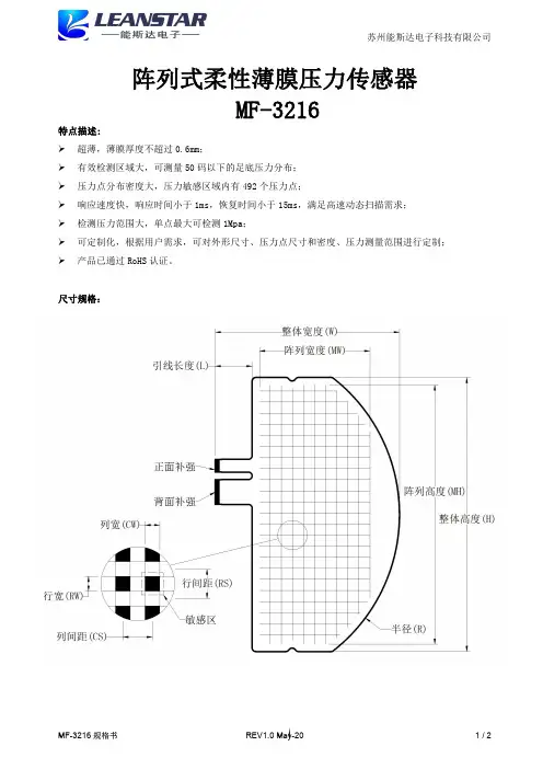
SF15系列柔性薄膜压力传感器规格书
- 格式:pdf
- 大小:722.08 KB
- 文档页数:3

MLH SeriesAll Metal Pressure SensorsDESCRIPTIONMLH Series pressure sensors combine Application Specific Integrated Circuit (ASIC) technology with a media isolated, metal diaphragm design. This digitally compensated sensor offers value and performance, making it the ideal pressure sensing solution for demanding applications. Fully temperature compensated, calibrated and amplified, the MLH is available in 50 psi to 8,000 psi pressure ranges.MLH sensors deliver ±0.25% full scale accuracy Best Fit Straight Line (BFSL) and as low as 2% total error over a temperature range of -40 °C to 125 °C [-40 °F to 257 °F]. Industry standard connectors and process ports are offered for enhanced reliability and user flexibility.The MLH has seven standard output options:A. 0.5 Vdc to 4.5 Vdc ratiometric output from 5 Vdc excitationB. 4 mA to 20 mA current from 9.5 Vdc to 30 Vdc excitationC. 1.0 Vdc to 6.0 Vdc regulated output from 8 Vdc to30 Vdc excitationD. 0.25 Vdc to 10.25 Vdc regulated output from 14 Vdc to30 Vdc excitationE. 0.5 Vdc to 4.5 Vdc regulated output from 7 Vdc to30 Vdc excitationF. 0 mV to 50 mV from 5 Vdc excitationG. 1 Vdc to 5 Vdc output from 8 Vdc to 30 Vdc excitationFEATURES• All metal wetted parts for use in wide variety of fluidapplications• No internal elastomeric seals mean no o-ring compatibilityissues• Amplified outputs eliminate cost of external amplifiers • Input reverse voltage and output short circuit protectionsguard against mis-wiring• Less than 2 ms response time provides accurate, highspeed measurement• Rated IP65 or better for protection from harsh environmentsPOTENTIAL APPLICATIONS • Compressors• Refrigeration and HVAC/R • General industrial • General hydraulics• Multiple transportation applications including braking andalternate fuels • MedicalMLH Series2 /sensingTable 1. Pressure Range Specifications 1(At 25 °C [77 °F] and at rated excitation unless otherwise specified.)psiPressure 50 100 150 200 250 300 500 1000 2000 3000 5000 8000 Proof pressure 150 300 450 600 750 900 1500 2000 4000 6000 7500 12000 Burst pressure 500 1000 1500 2000 2500 3000 5000 10000 20000 30000 30000 30000barPressure 6 10 16 25 40 60 100 160 250 350 500 550 Proof pressure 18 30 48 75 80 120 200 320 500 700 750 825 Burst pressure60 100 160 250 400 600 1000 1600 2068 2068 2068 2068Note:1. Comparable metric units follow same proof and burst specifications.Table 2. Physical and Environmental SpecificationsParameter Characteristic Material in contact with media stainless steel 300 series and Haynes 214 alloy, Hastelloy C22 sensor available (contact factory) Housing material black plastic – Amodel AS-4133 HS – PPA Weight 57.0 g [2.0 oz] (typical for Packard MetriPak and 1/8 NPT port) Shock 100 g peak [11 ms] Vibration MIL-STD-810C, Figure 514.2-5, Curve AK, Table 514.2-V, Random Vibration Test [overall g rms =20.7 min.]Compensated, operating and storage temperature range-40 °C to 125 °C [-40 °F to 257 °F]Table 3. Electrical Specifications (At 25 °C [77 °F] and at rated excitation unless otherwise specified.) Parameter Ratiometric(A)1 Current (B) Regulated(C) Regulated(D) Regulated(E) mV (F) Regulated(G) Zero output 0.5 Vdc4.0 mA1.0 Vdc0.25 Vdc0.5 Vdc0 ±2.5 mV1.0 VdcFull scale span (FSS) 4.0 Vdc (0.5 to 4.5 Vdc) 16 mA (4 to 20 mA) 5.0 Vdc (1.0 to 6.0 Vdc) 10.0 Vdc (0.25 to 10.25 Vdc) 4.0 Vdc (0.5 to4.5 Vdc) 50 mV (0 to 50 mV) 4.0 Vdc (1.0 to 5.0 Vdc)Excitation 5 Vdc (6.0 Vdc max.) 9.5 Vdc to 30.0 Vdc 8.0 Vdc to 30.0 Vdc 14.0 Vdc to 30.0 Vdc 7.0 Vdc to 30.0 Vdc5.0 Vdc (6.0 Vdc max.)8.0 Vdc to 30.0 VdcSupply current 4.0 mA typical (8 mA max.)N/A 5.0 mA typical (17 mA max.)5.0 mA typical (17 mA max.)5.0 mA typical (17 mA max.) 8.0 mA typical (17 mA max.) 5.0 mA typical (17 mA max.)Source (nominal) 1.0 mA N/A 1.0 mA 1.0 mA 1.0 mA N/A 1.0 mA Sink(nominal) 1.0 mA at zero outputN/A 1.0 mA at zero output1.0 mA at zero output1.0 mA at zero outputN/A 1.0 mA at zero outputSupplyrejection ratio 90 db 90 db 90 db 90 db 90 db N/A90 dbOutput impedance25 Ω max.N/A25 Ω max.25 Ω max.25 Ω max.2000 Ω 25 Ω max.Note:1. Maintains ratiometricity at 5 ±0.25 Vdc excitation. Product can tolerate 6 Vdc excitation without damage.All Metal Pressure SensorsHoneywell Sensing and Control 3Table 4. Performance Specifications (At 25 °C [77 °F] and at rated excitation unless otherwise specified.)Parameter Characteristic Response time <2 msAccuracy 1:>100 psi<100 psi±0.25% FSS ±0.50% FSS Total error band 2:Gage:<300 psig>300 psigSeal gage:>300 psisSeal gage without L, M, P termination:100 psis to 299 psis (-40 °C to 85 °C [-40 °F to 185 °F])100 psis to 299 psis (>85 °C to 125 °C [>185 °F to 257 °F])>300 psis (-40 °C to 125 °C [-40 °F to 257 °F])Seal gage with L, M, P termination:100 psis to 299 psis (-40 °C to 65 °C [-40 °F to 149 °F])100 psis to 299 psis (>65 °C to 125 °C [>149 °F to 257 °F])>300 psis (-40 °C to 65 °C [-40 °F to 149 °F])>300 psis (>65 °C to 125 °C [>149 °F to 257 °F])±3% FSS ±2% FSS ±2% FSS ±3% FSS ±10% FSS ±2% FSS ±10% FSS ±15% FSS ±5% FSS ±15% FSS Notes:1. Includes pressure non-linearity (BFSL), pressure hysteresis and non-repeatability. Thermal errors are not included.2. Includes zero error, span error, thermal effect on zero, thermal effect on span, thermal hysteresis, pressure-non-linearity,pressure hysteresis and non-repeatability.1Sensing and Control Honeywell1985 Douglas Drive North Golden Valley, MN 55422 /sensing 008118-5-EN IL50 GLO Printed in USAJanuary 2009Copyright © 2009. Honeywell International Inc. All rights reserved.Figure 2. Mounting Dimensions (For reference only. mm/(in).)Pin and Wire Codes (Option B – Packard)Pin Voltage Current a + Excitation + Excitation b Output - Excitation c Common No ConnectionA variety of pressure ports and electricaltermination connection options are available. Refer to the “How to Order” on previous page for possible combinations. Contact your Honeywell representative for details.WARNINGMISUSE OF DOCUMENTATION• The information presented in this product sheet is forreference only. Do not use this document as a product installation guide.• Complete installation, operation, and maintenanceinformation is provided in the instructions supplied with each product.Failure to comply with these instructions could result in death or serious injury.WARRANTY/REMEDYHoneywell warrants goods of its manufacture as being free of defective materials and faulty workmanship. Honeywell’s standard product warranty applies unless agreed to otherwise by Honeywell in writing; please refer to your order acknowledgement or consult your local sales office for specific warranty details. If warranted goods are returned to Honeywell during the period of coverage, Honeywell will repair or replace, at its option, without charge those items it finds defective. Theforegoing is buyer’s sole remedy and is in lieu of all other warranties, expressed or implied, including those of merchantability and fitness for a particular purpose. In no event shall Honeywell be liable for consequential, special, or indirect damages.While we provide application assistance personally,through our literature and the Honeywell web site, it is up to the customer to determine the suitability of the product in the application.Specifications may change without notice. Theinformation we supply is believed to be accurate and reliable as of this printing. However, we assume no responsibility for its use.WARNINGPERSONAL INJURYDO NOT USE these products as safety or emergency stop devices or in any other application where failure of the product could result in personal injury.Failure to comply with these instructions could result in death or serious injury.SALES AND SERVICEHoneywell serves its customers through a worldwide network of sales offices, representatives and distributors. For application assistance, current specifications, pricing or name of the nearest Authorized Distributor, contact your local sales office or:E-mail:*********************Internet: /sensingPhone and Fax: Asia Pacific +65 6355-2828 +65 6445-3033 Fax Europe +44 (0) 1698 481481 +44 (0) 1698 481676 Fax Latin America +1-305-805-8188 +1-305-883-8257 F ax USA/Canada +1-800-537-6945 +1-815-235-6847 +1-815-235-6545 F ax。
fsr压力传感器技术手册FSR 压力传感器(Force Sensing Resistor,力敏电阻)是一种具有出色性能和广泛应用的压力传感器。
它通过测量电阻值的变化来感应外界的压力变化,从而实现对压力的测量。
以下是一份FSR 压力传感器技术手册的大致内容:一、FSR 压力传感器简介1. 工作原理:FSR 压力传感器是一种基于压阻效应的传感器,当受到压力作用时,其电阻值会发生明显变化。
通过测量这种变化,可以获得压力的大小。
2. 特点:FSR 压力传感器具有高灵敏度、高线性度、良好的重复性和稳定性,适用于各种压力测量场景。
二、FSR 压力传感器的分类1. 按结构分类:FSR 压力传感器可分为薄膜型、硅膜型、陶瓷型等不同类型。
2. 按输出信号分类:FSR 压力传感器可分为模拟输出型和数字输出型。
三、FSR 压力传感器的主要性能指标1. 灵敏度:FSR 压力传感器的灵敏度指受压力变化引起的电阻变化率。
灵敏度越高,压力传感器的测量范围越大。
2. 线性度:FSR 压力传感器的线性度指传感器输出与输入压力之间的线性关系。
线性度越好,传感器的测量精度越高。
3. 精度:FSR 压力传感器的精度指传感器测量结果与真实值之间的偏差。
精度越高,传感器的可靠性越好。
4. 响应时间:FSR 压力传感器的响应时间指传感器输出信号达到90% 峰值的时间。
响应时间越短,传感器对压力变化的反应速度越快。
5. 工作温度范围:FSR 压力传感器的工作温度范围指传感器在正常工作条件下能稳定运行的温度范围。
工作温度范围越宽,传感器的适应性越强。
四、FSR 压力传感器的应用领域1. 电子设备:FSR 压力传感器广泛应用于电子设备中,如智能手机、平板电脑、笔记本等,实现对触摸屏、按键等部件的压力检测。
2. 汽车电子:FSR 压力传感器在汽车电子领域中的应用日益广泛,如汽车安全气囊、座椅调节器、车窗升降等系统。
3. 工业自动化:FSR 压力传感器在工业自动化领域中具有广泛应用,如压力控制系统、机器人抓取装置等。
Pressure sensors SPAW with display2d Internet: /catalogue/...Subject to change – 2022/10Pressure sensors SPAW with displayKey featuresAt a glance[1] 9 pressure ranges from–1 … +1 bar to 0 … +100 bar [2] Protection class IP67[3] 320° rotatable display[4] 1% accuracy, 0.15% repetitionaccuracy[5] Temperature of medium–20 … 85°C [6] Materials in contact with media:CrNiMo: 316L, from a measuring range of 10 bar the membrane consists of 13-8-PH[7] 4-digit LED display, easy to read,robust [8] Display– bar – MPa – kPa – psi – kgf/cm²[9] Simple operation, protected byPIN code[10] 320° rotatable housing [11] Electrical connection M12[12] G1/4 female thread or G1/2 malethreadProduct descriptionMain applicationsThe SPAW is an extremely robust pressure sensor with display used for measuring media pressures in 9 measuring ranges from as small as –1 ... 1 bar up to 0 ... 100 bar. It can measure all media which do not react aggressively with the stainless steel measuring cell and stainless steel housing. The switching outputs can be set quickly and easily using three but-tons. The high-quality 14-segment LED display can be rotated 320° and theorientation of the text can be rotated 180°. This ensures that the display is easily readable in every installation position. Different standard designs are available, e.g.:• G1/4 female thread or G1/2 male thread• 2 x PNP or 2 x NPN • 4 ... 20 mA or 0 ... 10 VThe pressure sensor SPAW is suitable for standard pressure measurement at an increased mechanical load. It canbe used in high pressure pneumatic systems and to monitor the pressure of liquid media (e.g. coolant/cooling circuits, etc.)Pressure sensors SPAW with display Key features3 2022/10 – Subject to change d Internet: /catalogue/...Pressure sensors SPAW with displayPeripherals overview4d Internet: /catalogue/...Subject to change – 2022/10Pressure sensors SPAW with displayType codes52022/10 – Subject to change d Internet: /catalogue/...6d Internet: /catalogue/...Subject to change – 2022/10Pressure sensors SPAW with displayData sheetFunctione.g. switching output 2PVe.g. switching output 2NA• Pressure measuring range up to 100 bar• For liquid media •For gaseous media1)For information about the area of use, see the EC declaration of conformity at: /catalogue/SPAW d Support/Downloads.If the devices are subject to usage restrictions in residential, commercial or light-industrial environments, further measures for the reduction of the emitted interference may be necessary.2)Note media resistance of parts that come into contact with the mediaPressure sensors SPAW with display Data sheet7 2022/10 – Subject to change d Internet: /catalogue/...Pressure sensors SPAW with displayData sheet1)CrNiMo group: Measuring range up to 6 bar 316L, from a measuring range of 10 bar the membrane consists of 13-8-PH2)Corrosion resistance class CRC 4 to Festo standard FN 940070Particularly high corrosion stress. Outdoor exposure under extreme corrosive conditions. Parts exposed to aggressive media, e.g. in the chemical or food industries. Such applications may need to be safeguarded by means of special testing (d also FN 940082), using appropriate media.8d Internet: /catalogue/...Subject to change – 2022/10Pressure sensors SPAW with display Data sheet9 2022/10 – Subject to change d Internet: /catalogue/...Pressure sensors SPAW with displayData sheet10d Internet: /catalogue/...Subject to change – 2022/10Pressure sensors SPAW with display Data sheet11 2022/10 – Subject to change d Internet: /catalogue/...Pressure sensors SPAW with displayAccessories1)Temperature-dependent operating pressure –0.95 ... 14 bar12d Internet: /catalogue/...Subject to change – 2022/10。
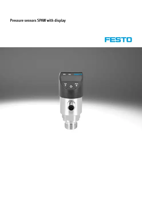
THIN FILM 4-20 MA OUTPUTTransducers are Shown with PS-4 Snubbers, sold separately15.75(.62)57.15(2.25)27.17(1.07)WIRING1 + RED2– BKPX205 Cable StylePX215 Connector StyleDimensions Shown in mm (in.)CANADA www.omega.ca Laval(Quebec) 1-800-TC-OMEGA UNITED KINGDOM www. Manchester, England0800-488-488GERMANY www.omega.deDeckenpfronn, Germany************FRANCE www.omega.frGuyancourt, France088-466-342BENELUX www.omega.nl Amstelveen, NL 0800-099-33-44UNITED STATES 1-800-TC-OMEGA Stamford, CT.CZECH REPUBLIC www.omegaeng.cz Karviná, Czech Republic596-311-899TemperatureCalibrators, Connectors, General Test and MeasurementInstruments, Glass Bulb Thermometers, Handheld Instruments for Temperature Measurement, Ice Point References,Indicating Labels, Crayons, Cements and Lacquers, Infrared Temperature Measurement Instruments, Recorders Relative Humidity Measurement Instruments, RTD Probes, Elements and Assemblies, Temperature & Process Meters, Timers and Counters, Temperature and Process Controllers and Power Switching Devices, Thermistor Elements, Probes andAssemblies,Thermocouples Thermowells and Head and Well Assemblies, Transmitters, WirePressure, Strain and ForceDisplacement Transducers, Dynamic Measurement Force Sensors, Instrumentation for Pressure and Strain Measurements, Load Cells, Pressure Gauges, PressureReference Section, Pressure Switches, Pressure Transducers, Proximity Transducers, Regulators,Strain Gages, Torque Transducers, ValvespH and ConductivityConductivity Instrumentation, Dissolved OxygenInstrumentation, Environmental Instrumentation, pH Electrodes and Instruments, Water and Soil Analysis InstrumentationHeatersBand Heaters, Cartridge Heaters, Circulation Heaters, Comfort Heaters, Controllers, Meters and SwitchingDevices, Flexible Heaters, General Test and Measurement Instruments, Heater Hook-up Wire, Heating Cable Systems, Immersion Heaters, Process Air and Duct, Heaters, Radiant Heaters, Strip Heaters, Tubular HeatersFlow and LevelAir Velocity Indicators, Doppler Flowmeters, LevelMeasurement, Magnetic Flowmeters, Mass Flowmeters,Pitot Tubes, Pumps, Rotameters, Turbine and Paddle Wheel Flowmeters, Ultrasonic Flowmeters, Valves, Variable Area Flowmeters, Vortex Shedding FlowmetersData AcquisitionAuto-Dialers and Alarm Monitoring Systems, Communication Products and Converters, Data Acquisition and Analysis Software, Data LoggersPlug-in Cards, Signal Conditioners, USB, RS232, RS485 and Parallel Port Data Acquisition Systems, Wireless Transmitters and Receivers。
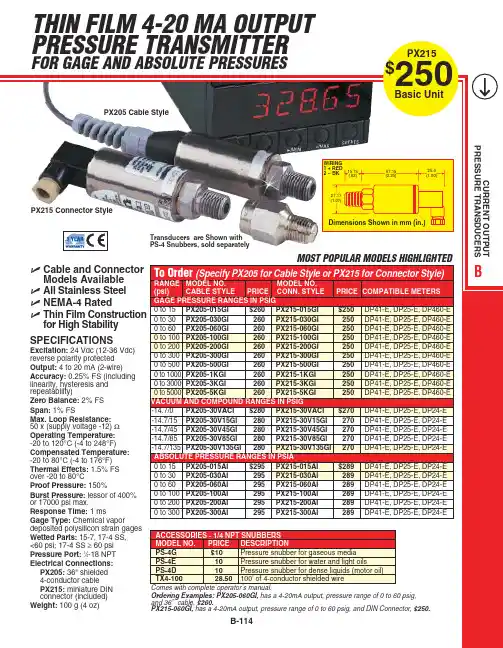
Spec.No.规格书编号:S0568Rev.:1.0Page:1/5深圳市信威电子有限公司版次Rev.变更内容Revision History发出日期Issue Date 制作Issue by 复核Checked by批准Approved by 1.0首版Original release2022-4-20黄哲伦/严子光1.产品简介本压力传感器是基于MEMS 技术的硅压阻式传感器,由扩散硅充油芯片和高精度的信号调理芯片组成。
芯体由316L 不锈钢膜片及壳体和硅油密封,产品外壳采用304F 不锈钢材质,该结构使之能够测量所有与316L 和304不锈钢兼容的流体介质。
外界压力作用在充油芯体上,产生的信号经过两次校准(模拟补偿+信号调理芯片处理)后,以I2C 的形式输出。
Each product has been calibrated in plant to ensure the well accuracy in different environment 每个产品都已经在工厂里进行了标定,以确保产品在各种环境中的测量精度Spec.No.规格书编号:S0568Rev.:1.0Page:2/5深圳市信威电子有限公司3.输出接口及管脚定义注:1.产品的内部电路已经在I2C 总线上放置了4.7K 的上拉电阻2.所有管脚与产品的金属外壳之间是绝缘的4.产品外形结构(单位:mm )5.功能描述5.1.工作模式传感器的默认工作模式为:产品上电后,进入到休眠状态,仅在接收到相应的I2C 命令后才会启动一次压力和温度的测量动作,之后再次自动进入休眠状态,以节省功耗。
5.2.上电启动及休眠唤醒当电源电压小于0.2V 时,传感器处于复位状态,在电源电压以最低10V/ms 的上升速率经过1ms 的延迟后,I2C 接口处于正常状态,可以接受主机命令,在经过2.5ms 的延迟后,传感器可以进行正常的压力和温度测量。
当传感器处于休眠状态时,在接收到主机命令后的0.5ms 时间内从休眠状态进入到工作模式,详细请参Spec.No.规格书编号:S0568Rev.:1.0Page:3/5深圳市信威电子有限公司照上电时序图6.I2C 接口6.1.I2C 接口电气特性在产品内部,I2C 总线的时钟信号线和数据线已经具有4.7k 的上拉电阻6.2.I2C 通讯速率本传感器的I2C 接口可工作于标准模式(100Kbit/s )、快速模式(400Kbit/s)、和高速模式(3.4Mbit/s)。
No.PS※※-OMT0006-BPressure Sensor for General FluidsPSE575/576/577Safety Instructions 2 Model Identification and How to Order 8 Names of Parts of Product and Handling Precautions 9 Mounting and Installation 10 Wiring 10 Troubleshooting 12 Specification 13 Specifications 13 Dimensions 15Safety InstructionsThese safety instructions are intended to prevent hazardous situations and/or equipment damage. These instructions indicate the level of potential hazard with the labels of "Caution", "Warning" or "Danger".They are all important notes for safety and must be followed in addition to International Standards (ISO/IEC)*1), and other safety regulations*2).*1) ISO 4414: Pneumatic fluid power -- General rules relating to systems.ISO 4413: Hydraulic fluid power -- General rules relating to systems.IEC 60204-1: Safety of machinery -- Electrical equipment of machines .(Part 1: General requirements)ISO 10218: Manipulating industrial robots -Safety. etc.*2) High Pressure Gas Safety Law.Caution Caution indicates a hazard with a low level of risk which, if not avoided, couldresult in minor or moderate injury.Warning Warning indicates a hazard with a medium level of risk which, if not avoided,could result in death or serious injury.Danger Danger indicates a hazard with a high level of risk which, if not avoided, willresult in death or serious injury.Warning1. The compatibility of the product is the responsibility of the person who designs theequipment or decides its specifications.Since the product specified here is used under various operating conditions, its compatibility withspecific equipment must be decided by the person who designs the equipment or decides itsspecifications based on necessary analysis and test results.The expected performance and safety assurance of the equipment will be the responsibility of the person who has determined its compatibility with the product.This person should also continuously review all specifications of the product referring to its latestcatalog information, with a view to giving due consideration to any possibility of equipment failure when configuring the equipment.2. Only personnel with appropriate training should operate machinery and equipment.The product specified here may become unsafe if handled incorrectly.The assembly, operation and maintenance of machines or equipment including our products must be performed by an operator who is appropriately trained and experienced.3. Do not service or attempt to remove product and machinery/equipment until safety isconfirmed.1. The inspection and maintenance of machinery/equipment should only be performed after measuresto prevent falling or runaway of the driven objects have been confirmed.2. When the product is to be removed, confirm that the safety measures as mentioned above areimplemented and the power from any appropriate source is cut, and read and understand the specific product precautions of all relevant products carefully.3. Before machinery/equipment is restarted, take measures to prevent unexpected operation and malfunction.4. Contact SMC beforehand and take special consideration of safety measures if theproduct is to be used in any of the following conditions.1. Conditions and environments outside of the given specifications, or use outdoors or in a placeexposed to direct sunlight.2. Installation on equipment in conjunction with atomic energy, railways, air navigation, space, shipping,vehicles, military, medical treatment, combustion and recreation, or equipment in contact with food and beverages, emergency stop circuits, clutch and brake circuits in press applications, safety equipment or other applications unsuitable for the standard specifications described in the product catalog.3. An application which could have negative effects on people, property, or animals requiring specialsafety analysis.4. Use in an interlock circuit, which requires the provision of double interlock for possible failure byusing a mechanical protective function, and periodical checks to confirm proper operation.Safety InstructionsCaution1.The product is provided for use in manufacturing industries.The product herein described is basically provided for peaceful use in manufacturing industries.If considering using the product in other industries, consult SMC beforehand and exchange specifications or a contract if necessary.If anything is unclear, contact your nearest sales branch.Limited warranty and Disclaimer/Compliance Requirements The product used is subject to the following "Limited warranty and Disclaimer" and "Compliance Requirements".Read and accept them before using the product.Limited warranty and Disclaimer1. The warranty period of the product is 1 year in service or 1.5 years after the product isdelivered,whichever is first.*2)Also, the product may have specified durability, running distance or replacement parts.Please consult your nearest sales branch.2. For any failure or damage reported within the warranty period which is clearly ourresponsibility, a replacement product or necessary parts will be provided.This limited warranty applies only to our product independently, and not to any other damage incurred due to the failure of the product.3. Prior to using SMC products, please read and understand the warranty terms anddisclaimers noted in the specified catalog for the particular products.*2) Vacuum pads are excluded from this 1 year warranty.A vacuum pad is a consumable part, so it is warranted for a year after it is delivered.Also, even within the warranty period, the wear of a product due to the use of thevacuum pad or failure due to the deterioration of rubber material are not covered bythe limited warranty.Compliance Requirements1. The use of SMC products with production equipment for the manufacture of weapons ofmass destruction (WMD) or any other weapon is strictly prohibited.2. The exports of SMC products or technology from one country to another are governed bythe relevant security laws and regulation of the countries involved in the transaction. Prior to the shipment of a SMC product to another country, assure that all local rules governing that export are known and followed.CautionSMC products are not intended for use as instruments for legal metrology.Products that SMC manufactures or sells are not measurement instruments that are qualified by pattern approval tests relating to the measurement laws of each country.Therefore, SMC products cannot be used for business or certification ordained by the measurement laws of each country.Caution■After maintenance is complete, perform appropriate functional inspections and leak tests.Stop operation if the equipment does not function properly or there is a leakage of fluid.When leakage occurs from parts other than the piping, the product might be faulty.Disconnect the power supply and stop the fluid supply.Do not apply fluid under leaking conditions.Safety cannot be assured in the case of unexpected malfunction.■Use within the specified operating pressure.Otherwise it can cause damage to the Pressure Sensor or inability to measure correctly.If fluid is supplied at a pressure exceeding the proof pressure, the ceramic diaphragm will be damaged. A significantly damaged diaphragm will result in external leakage. In addition, the power supply is short circuited depending on the applied fluid. Please use a power supply which includes short circuit protection.■NOTE○Follow the instructions given below when designing, selecting and handling the product.●The instructions on design and selection (installation, wiring, environment, adjustment,operation, maintenance, etc.) described below must also be followed.*Product specifications∙Use the specified voltage.Otherwise failure or malfunction can result.∙Applicable fluid is a fluid that does not corrode C3604 + electroless nickel plated, AI203 (aluminum oxide) and FKM.Do not use a fluid containing chemicals, synthetic oils including organic solvent, salt and corrosive gases.Otherwise, damage to the product and malfunction can result.Check the details of the specifications before using.∙Reserve a space for maintenance.Allow sufficient space for maintenance when designing the system.∙A ceramic diaphragm type pressure sensor is used in this product. The ceramic diaphragm can be damaged by overpressure from hydraulic shock, which can be generated when condensate in the fluid collides with the sensor during pressure fluctuation. This is also known as "water hammer".To mitigate hydraulic shock, it is recommended to insert an orifice between the fluid and the sensor. A gas pocket also needs to be between the orifice and the sensor to cushion the shock pulse. The sensor would then need to be located above the orifice with the orifice mounted vertically so that no fluid gets between the orifice and sensor.Some recommended and NOT recommended examples are shown in the following figure. PartnumbersZS-31-X175 or X188 are applicable orifices (called throttles in product literature).●Product handling*Installation∙Follow the specified tightening torque.Excessive tightening torque can break the Pressure Sensor.Insufficient tightening torque can displace the Pressure Sensor from the original position or loosen the mounting∙When piping, apply a spanner vertically to the piping section for the sensor.Applying the wrench in other position can break the Pressure Sensor∙Be sure to ground terminal FG when using a commercially available switch-mode power supply.∙Do not drop, hit or apply shock to the Pressure Sensor.Otherwise damage to the internal parts can result, causing malfunction.∙Do not pull the lead wire forcefully, not lift the product by pulling the lead wire. (Tensile force 35N or less) Hold the body when handling to avoid the damage of the Pressure Sensor lead to cause the failure andmalfunction.∙For piping of the Pressure Sensor, hold the piping with a spanner on the metal part of the piping(Piping attachment).Holding other part with spanner leads to damage the Pressure Sensor.∙Eliminate any dust left in the piping by air blow before connecting the piping to the product.Otherwise it can cause damage or malfunction.∙Do not insert metal wires or other foreign matter into the pressure measurement port.It can damage the Pressure Sensor causing failure or malfunction.*Wiring∙Do not pull the lead wires.In particular, never lift a Pressure Sensor equipped with fitting and piping by holding the lead wires.∙Avoid repeatedly bending or stretching the lead wire, or placing heavy load on them.Repetitive bending stress or tensile stress can cause the sheath of the wire to peel off, or breakage of the wire.If the lead wire can move, fix it near the body of the product.The recommended bend radius of the lead wire is 6 times the outside diameter of the sheath, or 33 times the outside diameter of the insulation material, whichever is larger.Replace the damaged lead wire with a new one.∙Wire correctly.Incorrect wiring can break the Pressure Sensor.∙Do not perform wiring while the power is on.Otherwise damage to the internal parts can result, causing malfunction.∙Do not route wires and cables together with power or high voltage cables.Otherwise the product can malfunction due to interference of noise and surge voltage from power and highvoltage cables to the signal line. Route the wires (piping) of the product separately from power or high voltage cables.∙Confirm proper insulation of wiring.Poor insulation (interference from another circuit, poor insulation between terminals, etc.) can lead to excess voltage or current being applied to the product, causing damage.∙Keep wiring as short as possible to prevent interference from electromagnetic noise and surge voltage.Do not use a cable longer than 30 m.Wire the DC(-) line(blue) as close as possible to the power supply.∙Ensure that the FG terminal is connected to ground when using a commercially available switch-mode power supply. When a switch-mode power supply is connected to the product, switching noise will be superimposed and the product specification can no longer be met. This can be prevented by insertinga noise filter, such as a line noise filter and ferrite core, between the switch-mode power supply andthe product, or by using a series power supply instead of a switch-mode power supply.*Environment∙Do not use the product in area that is exposed to corrosive gases, chemicals, sea water, water or steam.Otherwise failure or malfunction can result.∙Do not use in a place where the product could be splashed by oil or chemicals.If the product is to be used in an environment containing oils or chemicals such as coolant or cleaning solvent, even for a short time, it may be adversely affected (damage, malfunction, or hardening of the lead wires).∙Do not use in an area where electrical surges are generated. (EMI or Electro Magnetic Interference) If there is equipment which generates a large amount of EMI (solenoid type lifter, high frequency induction furnace, motor, etc.) close to the Pressure Sensor, this may cause deterioration or breakage of the internal circuit of the Pressure Sensor. Avoid sources of surge generation and crossed lines.∙The product is CE marked, but not immune to lightning strikes. Take measures against lightning strikes in the system.∙Mount the product in a place that is not exposed to vibration or impact.Otherwise failure or malfunction can result.∙Prevent foreign matter such as remnant of wires from entering the Pressure Sensor.Take proper measures for the remnant not to enter the Pressure Sensor in order to prevent failure or malfunction. ∙Do not use the product in an environment that is exposed to temperature cycle.Heat cycles other than ordinary changes in temperature can adversely affect the inside of the product.∙Do not expose the product to direct sunlight.If using in a location directly exposed to sunlight, shade the product from the sunlight.Otherwise failure or malfunction can result.∙Keep within the specified fluid and ambient temperatures range.The fluid and ambient temperatures should be -10 to 60 °C. Operation under low temperature leads to cause damage or operation failure due to frozen moist in the fluid or air.Protection against freezing is necessary. Air dryer is recommended for elimination of drain and water.Avoid sudden temperature change even within specified temperature.∙Do not operate close to a heat source, or in a location exposed to radiant heat.Otherwise malfunction can result.*Adjustment and Operation∙Do not short-circuit the load.∙If using the product to detect very small pressure rates, warm up the product for 20 to 30 minutes first.There will be a drift on the analogue output of approximate ±1% immediately after the power supply is turned on, within 10 minutes.*Maintenance∙Turn off the power supply, stop the supplied air, exhaust the residual pressure and verify the release of air before performing maintenance.There is a risk of unexpected malfunction.∙Perform regular maintenance and inspections.There is a risk of unexpected malfunction.∙Perform drainage regularly.If condensate enters the secondary side, it can cause operating failure of pneumatic equipment.∙Do not use solvents such as benzene, thinner etc. to clean the Pressure Sensor.They could damage the surface of the body and erase the markings on the body.Use a soft cloth to remove stains. For heavy stains, use a cloth soaked with diluted neutral detergent and fully squeezed, then wipe up the stains again with a dry cloth.○Names of parts of product•Only fluids which are non-corrosive to C3604 + electroless nickel plated, AI203 (aluminum oxide) and FKM should be used.○Handling precautions■Wiring○Connector pin numbersWhen the lead wire and connector (ZS-37-A or ZS-37-B) designated for the PSE570 is used, the wire colours will apply as shown in the diagram.Connector pin numbers (on the lead wire)•ZS-37-A•ZS-37-B*: The unconnected terminals are used in SMC, so please do not connect them.○How to connect the body and the lead wire and connector∙Align the lead wire connector with the connector key groove, and insert vertically.∙Connection is complete when the knurled part is fully tightened. Check that the connection is not loose.○Internal circuit and wiring example∙Output specificationPSE57□-02Voltage output: 1 to 5 VOutput impedance: Approx. 1 kΩPSE57□-02-28Current output: 4 to 20 mAAllowable load impedance:500 Ω or less (at 24 VDC)100 Ω or less (at 12 VDC)*: The unconnected terminals are used in SMC, so please do not connect them.○Analogue outputModel Rated pressure range A BPSE575 0 to 2 MPa 0 2 MPaPSE576 0 to 5 MPa 0 5 MPaPSE577 0 to 10 MPa 0 10 MPa■Dimensions∙Lead wire and M12 connector ZS-37-AZS-37-B∙Adapter with throttleZS-31-X1754-14-1, Sotokanda, Chiyoda-ku, Tokyo 101-0021 JAPANTel: + 81 3 5207 8249 Fax: +81 3 5298 5362URL Note: Specifications are subject to change without prior notice and any obligation on the part of the manufacturer.。

36智能电子式压力传感器说明书IP68模拟量输出RM-PA1140/50-PA41-CN-V1.147面板控制与显示功能特征Output 1滞后功能/N.O.(Hno)滞后功能/N.C.(Hnc)视窗功能/N.O.(Fno)视窗功能/N.C.(Fnc)Output 2模拟输出4~20 mA(I)模拟输出0~10 V(U)从压力传感器 探测到系统当前的压力,显示系统当前压力(bar ;Psi;kgf;MPa),同时根据设置输出状态,产生两个输出信号。
滞后作用如果系统压力与预设的差不多,那么滞后现象保持在输出平稳的状态。
当系统压力增大的时候,输出端能够达到打开开关的点(SP1);当系统压力再一次减小时,输出端能够达到关闭开关的点(rP1)。
滞后调整的方法:首先打开开关的点确定好,然后根据不同的要求再重新确定。
压力 通过视窗的作用能监测到明确的可以被接受的值。
当系统在开(SP1) 和关 (rP1) 之间变化时,输出接通 (视窗作用/常开) 或不接通 (视窗作用/常闭)。
通过 SP1 和 rP1的不同可以设定视窗的宽度。
SP1为上限值,rP1为下限值。
Psp rPt滞后Hno Hnc视窗功能101049运行模式(正常工作模式)·当外部提供电压时,装置为工作模式,根据它所设置的参数来监控和开关输出。
·模拟信号的输出值与系统压力有关。
·数码管显示表明当前系统的压力,红色二极管发光表示晶体管输出时开关的状态。
()·MODE/ENTER MODE/E 键键显示模式显示参数和设置参数值当很快按下“”键时,装置为参数值可读的显示模式,装置内部的进程和输出仍然为工作模式。
·每按一下“NTER”,就会出现一个参数名称。
·当快速按“LEARN/SET”时,对应的参数值显示5秒,5秒以后装置回到工作模式。
设置模式(参数值的设定)选择确定一个参数值后(显示模式),装置就会经过一个设置模式,一直按着“LEARN/SET”键直到显示的参数值改变, 装置的内部仍为工作模式。

MPXM2053GS MPXM2053GST1MPX2053D MPXV2053DPMPX2053Rev 9, 10/2012Freescale Semiconductor Data Sheet: Technical Data50 kPa On-Chip Temperature Compensated and Calibrated Silicon Pressure SensorsThe MPX2053 series devices are silicon piezoresistive pressure sensorsthat provide a highly accurate and linear voltage output directly proportional to the applied pressure. A single, monolithic silicon diaphragm with the strain gauge and an integrated thin-film resistor network. Precise span and offset calibration with temperature compensation are achieved by laser trimming.Features•Temperature Compensated Over 0︒C to +85︒C •Easy-to-Use Chip Carrier Package Options •Ratiometric to Supply Voltage•Gauge Ported and Non Ported Options •Available in Easy-to-Use Tape & Reel •Differential and Gauge Pressure OptionsORDERING INFORMATIONDevice NameCase No.# of Ports Pressure Type Device MarkingNoneSingleDualGaugeDifferentialAbsoluteSmall Outline Package (MPXV2053G Series)MPXV2053GP 1369••MPXV2053GP MPXV2053DP 1351••MPXV2053DP Unibody Package (MPX2053 Series)MPX2053D 344••MPX2053D MPX2053DP 344C ••MPX2053DP MPX2053GP 344B••MPX2053GP MPAK Package (MPXM2053 Series)MPXM2053D 1320••MPXM2053D MPXM2053DT11320••MPXM2053D MPXM2053GS 1320A ••MPXM2053GS MPXM2053GST11320A••MPXM2053GSMPX2053Series0 to 50 kPa (0 to 7.25 psi)40 mV Full Scale(Typical)Application Examples•Pump/Motor Control •Robotics•Level Detectors •Medical Diagnostics •Pressure Switching•Blood Pressure MeasurementSMALL OUTLINE PACKAGESMPXV2053GP CASE 1369-01 MPXV2053DP CASE 1351-01MPXM2053D/DT1CASE 1320-02MPXM2053GS/GST1CASE 1320A-02MPAK PACKAGESUNIBODY PACKAGESMPX2053D CASE 344-15MPX2053GP CASE 344B-01MPX2053DP CASE 344C-01PressureOperating CharacteristicsMaximum RatingsTable 1. Operating Characteristics (V S = 10 V DC , T A = 25°C unless otherwise noted, P1 > P2)CharacteristicSymbol Min Typ Max Units Pressure Range (1)1. 1.0 kPa (kiloPascal) equals 0.145 psi.P OP 0—50kPa Supply Voltage (2)2.Device is ratiometric within this specified excitation range. Operating the device above the specified excitation range may induce additional error due to device self-heating.V S —1016V DC Supply Current I O — 6.0—mAdc Full Scale Span (3)3.Full Scale Span (V FSS ) is defined as the algebraic difference between the output voltage at full rated pressure and the output voltage at the minimum rated pressure.V FS 38.54041.5mV Offset (4)4.Offset (V off ) is defined as the output voltage at the minimum rated pressure.—–1.0— 1.0mV Sensitivity —∆V/∆P —0.8—Non-Linearity—–0.6—0.4%V FS Pressure Hysteresis (0 to 50 kPa)——±0.1—%V FS Temperature Hysteresis (-40° to 125°C)——±0.5—%V FS Temperature Coefficient of Full Scale TCV FS –2.0— 2.0%V FS Temperature Coefficient of Offset TCV OFF –1.0— 1.0mV Input Impedance Z IN 1000—2500ΩOutput ImpedanceZ OUT 1400—3000ΩResponse Time (5) (10% to 90%)5.Response Time is defined as the time for the incremental change in the output to go from 10% to 90% of its final value when subjected to a specified step change in pressure.t R — 1.0—ms Warm-Up Time ——20—ms Offset Stability (6)6.Offset stability is the product's output deviation when subjected to 1000 hours of Pulsed Pressure, Temperature Cycling with Bias Test.——±0.5—%V FSTable 2. Maximum Ratings (1)RatingMax ValueUnit Supply Voltage 16V Pressure (P1 > P2)200kPa Storage Temperature–40 to +125︒C Operating Temperature Range–40 to +125︒C1. Exposure beyond the specified limits may cause permanent damage or degradation to the device.PressureFigure 1 shows a block diagram of the internal circuitry integrated on a pressure sensor chip.Figure 1. Temperature Compensated Pressure Sensor SchematicVoltage Output versus Applied Differential PressureThe differential voltage output of the sensor is directly proportional to the differential pressure applied.The output voltage of the differential or gauge sensor increases with increasing pressure applied to the pressureside relative to the vacuum side. Similarly, output voltage increases as increasing vacuum is applied to the vacuum side relative to the pressure side.On-Chip Temperature Compensation and CalibrationFigure 2 shows the minimum, maximum and typical output characteristics of the MPX2053 series at 25︒C. The output is directly proportional to the differential pressure and is essentially a straight line.A silicone gel isolates the die surface and wire bonds from the environment, while allowing the pressure signal to be transmitted to the silicon diaphragm.Figure 2. Output vs. Pressure DifferentialV S 3X-ducer Sensing ElementThin Film Temperature Compensationand Calibration24V out+V out-1GNDO u t p u t (m V d c )kPa PSI40353025151050-512.51.8253.637.55.4507.2520MAXTYPMINOFFSET (TYP)SPAN RANGE (TYP)V S = 10 Vdc T A = 25︒CPressureLINEARITYLinearity refers to how well a transducer's output follows the equation: V out = V off + sensitivity x P over the operating pressure range. There are two basic methods for calculating nonlinearity: (1) end point straight line fit (see Figure 3) or (2)a least squares best line fit. While a least squares fit gives the “best case” linearity error (lower numerical value), the calculations required are burdensome.Conversely, an end point fit will give the “worst case” error (often more desirable in error budget calculations) and the calculations are more straightforward for the user. The specified pressure sensor linearities are based on the end point straight line method measured at the midrange pressure.Figure 3. Linearity Specification ComparisonFigure 4 illustrates the differential or gauge configuration in the basic chip carrier (Case 344). A silicone gel isolates the die surface and wire bonds from the environment, while allowing the pressure signal to be transmitted to the silicon diaphragm.The MPX2053 series pressure sensor operatingcharacteristics and internal reliability and qualification testsare based on use of dry air as the pressure media. Media other than dry air may have adverse effects on sensorperformance and long term reliability. Contact the factory for information regarding media compatibility in your application. Refer to application note AN3728, for more information regarding media compatibility.Figure 4. Unibody Package — Cross-Sectional Diagram (Not to Scale)R e l a t i v e V o l t a g e O u t p u tPressure (% Full scale)Silicone Die CoatDieP1P2Wire BondLead FrameRTV Die BondEpoxy CaseStainless Steel Metal CoverPACKAGE DIMENSIONS Array CASE 344-15ISSUE AAUNIBODY PACKAGEISSUE B UNIBODY PACKAGEPACKAGE DIMENSIONSCASE 344C-01ISSUE B UNIBODY PACKAGEPACKAGE DIMENSIONSPACKAGE DIMENSIONSCASE 1369-01ISSUE DSMALL OUTLINE PACKAGEISSUE BCASE 1320-02ISSUE BPressureISSUE APressurePACKAGE DIMENSIONSISSUE APressure Table3. Revision HistoryRevision number RevisiondateDescription of changes910/2012 •Deleted references to device number MPXV2053GVP throughout the documentHow to Reach Us: Home Page: Web Support: /support Information in this document is provided solely to enable system and software implementers to use Freescale products. There are no express or implied copyright licenses granted hereunder to design or fabricate any integrated circuits based on the information in this document.Freescale reserves the right to make changes without further notice to any products herein. Freescale makes no warranty, representation, or guarantee regarding the suitability of its products for any particular purpose, nor does Freescale assume any liability arising out of the application or use of any product or circuit, and specifically disclaims any and all liability, including without limitation consequential or incidental damages. “Typical” parameters that may be provided in Freescale data sheets and/or specifications can and do vary in different applications, and actual performance may vary over time. All operating parameters, including “typicals,” must be validated for each customer application by customer’s technical experts. Freescale does not convey any license under its patent rights nor the rights of others. Freescale sells products pursuant to standard terms and conditions of sale, which can be found at the following address: /salestermsandconditions.Freescale, the Freescale logo, Energy Efficient Solutions logo, are trademarks of Freescale Semiconductor, Inc., Reg. U.S. Pat. & Tm. Off. Xtrinsic is a trademark of Freescale Semiconductor, Inc. All other product or service names are the property of their respective owners.© 2012 Freescale Semiconductor, Inc.MPXM2053GS MPXM2053GST1MPX2053D MPXV2053DP。

93Kulite 压力传感器规格明细表型号量程范围工作方式工作温度输出固有频率外形尺寸或接口XCQ-050 25-500PSI A.G.SG.D -55℃-120℃ 100 mV 330-1300KHZ Φ1.4×5.1XCQ-062 25-500PSI A.G.SG.D -55℃-240℃ 100 mV 330-1300KHZ Φ1.6×9.5 XCS/W062 5/15PSIA.G.SG.D-55℃-120℃ 200 mV 255KHZΦ1.6×9.5XCE-062 25-500PSI A.G.SG.D-55℃-273℃ 100 mV 330-1300KHZ Φ1.6×9.5 XCQ-080 105-2000PSI A.G.SG.D -55℃-204℃ 100 mV 210-1250KHZ Φ2.0×6.4 XCQ-093 10-2000PSI A.G.SG.D -55℃-204℃ 100 mV 210-1250KHZ Φ2.4×9.5 XCS-2093 5-50PSIA.G.SG.D-55℃-204℃ 50 mV300 mV150-300KHZΦ2.4×9.5XCE-093 10-2000PSI A.G.SG.D -55℃-273℃ 100 mV 210-1250KHZ Φ2.4×9.5 CCQ-093 10-500PSI A.G.SG.D -195℃-120℃ 100 mV210-840KHZ Φ2.4×9.5XQ-140 5-500PSI A.G.SG.D -55℃-120℃ 100 mV 180-840KHZ Φ3.6×7.6 微 小 型XCQ-152 25-500PSI A.G.SG.D-55℃-120℃ 100 mV 180-840KHZ Φ3.8×7.6XCE-152 25-500PSI A.G.SG.D -55℃-273℃ 100 mV300-840KHZ Φ3.8×7.6LQ-125 5-500PSI A.G.SG.D-55℃-204℃ 100 mV 300-840KHZ 4.1×9.6×1.4LQ-125 5-500PSI A.G.SG.D -55℃-204℃ 100 mV 160-840KHZ 4.1×9.6×1.4 LE-125 25-500PSI A.G.SG.D -55℃-235℃ 100 mV 300-840KHZ 4.1×9.6×1.4 扁 平 型LQ-47 25-500PSI A.G.SG.D -55℃-204℃ 100 mV 300-840KHZ 4.1×9.5×0.63 XT-140 25-500PSI A.G.SG.D -55℃-204℃ 100 mV330-840KHZ 6-32NC-2A XT-190 10-300PSI A.G.SG.D -55℃-204℃ 100 mV 210-1250KHZ 10-32NVF-2AXCS/W-190 5/15PSIA.G.SG.D -55℃-204℃ 150-200 mV 150-200KHZ 10-32VND-2AXST-190 5-250PSI A.G.SG.D -55℃-204℃ 75 mV 160-680KHZ 10-32VND-2A XTC-190 5-3000PSI A.G.SG.D -55℃-204℃ 100 mV 160-1250KHZ 10-32VND-2A XTE-190 5-3000PSI A.G.SG.D -55℃-235℃ 100 mV 160-1250KHZ 10-32VND-2A 小 型 螺 纹 型CT-190 5-3000PSI A.G.SG.D -195℃-120℃ 100 mV 160-1250KHZ 10-32VND-2A XT-375 5-3000PSI A.G.SG.D -25℃-204℃ 150 mV160-1250KHZ 3/8-24UNJF-3AXCS/W-375 5. 15PSI A.G.SG.D -55℃-204℃ 150-250 mV 150-200KHZ 3/8-24UNJF-3AXST-375 5-250PSI A.G.SG.D -55℃-204℃ 100 mV 160-680KHZ 3/8-24UNJF-3A XTE-375 5-3000PSI A.G.SG.D -55℃-203℃ 100 mV 160-1250KHZ 3/8-24UNJF-3A CT-375 5-3000PSI A.G.SG.D -195℃-120℃ 100 mV 160-1250KHZ 3/8-24UNJF-3A HKS-375 1000-30000PSI SG -55℃-150℃ 100 mV 500-725KHZ 3/8-24UNJF-3A 标 准 带 螺 纹 型ET-375 5-500PSI A.G.SG -55℃-120℃ 0-5V 160-80KHZ 3/8-24UNJF-3A XTM-1090/M 10-5000PSI A.G.SG.D -55℃-175℃ 75 mV65-1120KHZ 10-32UNJF-2A(M5×0. 8)XTM-E190/M 10-5000PSI A.G.SG.D -55℃-232℃ 75 mV65-1120KHZ 10-32UNJF-2A(M5×0.8 )小 型 系 列HKM-375/M 25-2000PSI A.G.SG.D -55℃-175℃ 100 mV 120-1600KHZ 3/8-24UNJF(M10×1)94SUNSTAR商斯达实业集团是集研发、生产、工程、销售、代理经销、技术咨询、信息服务等为一体的高科技企业,是专业高科技电子产品生产厂家,是具有10多年历史的专业电子元器件供应商,是中国最早和最大的仓储式连锁规模经营大型综合电子零部件代理分销商之一,是一家专业代理和分銷世界各大品牌IC芯片和電子元器件的连锁经营綜合性国际公司,专业经营进口、国产名厂名牌电子元件,型号、种类齐全。
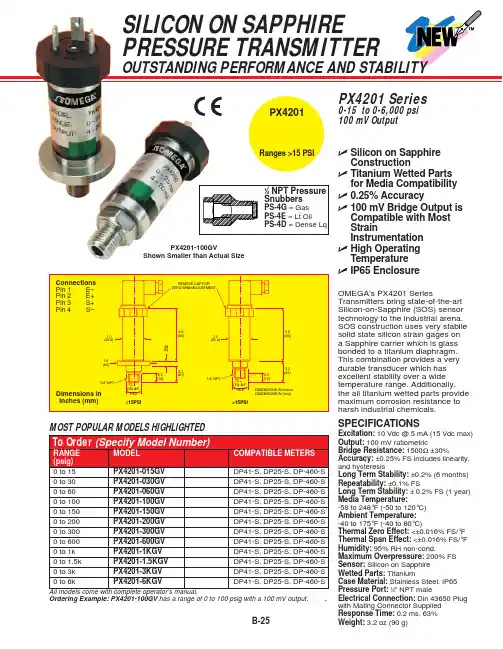
B-25Ordering Example:PX4201-100GV has a range of 0 to 100 psig with a 100 mV output,.SILICON ON SAPPHIRE PRESSURE TRANSMITTEROUTSTANDING PERFORMANCE AND STABILITYߜSilicon on Sapphire ConstructionߜTitanium Wetted Parts for Media Compatibility ߜ0.25% Accuracyߜ100 mV Bridge Output is Compatible with Most StrainInstrumentation ߜHigh Operating Temperature ߜIP65 EnclosureOMEGA’s PX4201 SeriesTransmitters bring state-of-the-art Silicon-on-Sapphire (SOS) sensor technology to the industrial arena. SOS construction uses very stabile solid state silicon strain gages on a Sapphire carrier which is glass bonded to a titanium diaphragm.This combination provides a very durable transducer which hasexcellent stability over a wide temperature range. Additionally, the all titanium wetted parts provide maximum corrosion resistance to harsh industrial chemicals.SPECIFICATIONSExcitation:10 Vdc @ 5 mA (15 Vdc max)Output:100 mV ratiometricBridge Resistance:1500Ω±30%Accuracy:±0.25% FS includes linearity, and hysteresisLong Term Stability: ±0.2% (6 months)Repeatability:±0.1% FSLong Term Stability: ±0.2% FS (1 year)Media Temperature:-58 to 248°F (-50 to 120°C)Ambient Temperature:-40 to 175°F (-40 to 80°C)Thermal Zero Effect:<±0.016% FS/°F Thermal Span Effect:<±0.016% FS/°F Humidity: 95% RH non-cond.Maximum Overpressure: 200% FS Sensor:Silicon on Sapphire Wetted Parts: TitaniumCase Material:Stainless Steel, IP65Pressure Port:1⁄4" NPT maleElectrical Connection:Din 43650 Plug with Mating Connector Supplied Response Time: 0.2 ms, 63% Weight:3.2 oz (90 g)PX4201-100GVShown Smaller than Actual SizePX4201 Series0-15 to 0-6,000 psi 100 mV OutputRanges >15 PSIPX 4201。
B-61THIN-FILM PRESSURE TRANSDUCER FOR OIL WELL LOGGING TOOLSULTRA-HIGH LONG-TERM STABILITYPX3400 SeriesmV/V Output0-1000 to 0-20,000 psi absolute 0-70 to 0-1400 bar absolute1 bar = 14.5 psi1 kg/cm 2= 14.22 psi1 atmosphere = 14.7 psi = 29.93inHg = 760.2 mmHg = 1.014 barPX3425-0004, $1395,shown smaller thanactual size.ߜVibration Resistance ߜOutstanding Stability at High Temperatures ߜSmall 19 mm (0.75")Body Diameter ߜHigh OperatingTemperature—Up To 177°C (350°F)ߜSolid State Reliability ߜGaged Diaphragm for Accurate Data and Fast Warm-UpߜBuilt-In Temperature Sensor for Thermal CorrectionߜStainless Steel Wetted PartsߜAvailable with Inconel ®Wetted Parts for Wells with Sour Gas or for Brine-Induced WellsOMEGA’s PX3400 Series pressure transducers have earned areputation for high performance,reliability, and stability in tough, real-world applications. They are particularly useful in deep well tools,with a narrow body diameter of 19mm (0.75") and pressure ranges up to 20,000 psi (1400 bar). Two models are available: the PX3425operates at up to 121°C (250°F),and the high-temperature PX3435 operates at up to 177°C (350°F). These outstanding transducers use OMEGA’s advanced sputtered thin-film sensor technology.Thousands of them are used on oil well logging tools throughout the world.Stability in such operations is critical. A transducer that shifts during a logging cycle invalidates costly data. The PX3400 Series uses thin-film strain gages, sputter deposited on a metal diaphragm.This advanced-technology gage system provides superior stability,especially at the high temperatures often found in oil wells.The diaphragm is machined from vacuum-remelted 17-4 PH stainless steel with elaborate annealing,aging, and stress-relieving processes to ensure a stable system. Thegaged-diaphragm design minimizes the number of components and welds in the transducer, increasing the reliability and precision oflogging data. The heat-sink effect of the diaphragm and the high bridge resistance reduce gage self-heating,decrease warm-up time, andconserve battery power. A built-in platinum resistance temperature element (RTD) provides data for correcting temperature effects using an external microprocessor. OMEGA’s PX3400 Series transducer can be modified to meet your design requirements. A broad selection of optional features is available,including pressure and electrical connections, special testing,additional thermal compensation,and 200°C (400°F) operating temperatures.DISCONTINUEDDISCONTINUEDDISCONTINUEDCANADA www.omega.ca Laval(Quebec) 1-800-TC-OMEGA UNITED KINGDOM www. Manchester, England0800-488-488GERMANY www.omega.deDeckenpfronn, Germany************FRANCE www.omega.frGuyancourt, France088-466-342BENELUX www.omega.nl Amstelveen, NL 0800-099-33-44UNITED STATES 1-800-TC-OMEGA Stamford, CT.CZECH REPUBLIC www.omegaeng.cz Karviná, Czech Republic596-311-899TemperatureCalibrators, Connectors, General Test and MeasurementInstruments, Glass Bulb Thermometers, Handheld Instruments for Temperature Measurement, Ice Point References,Indicating Labels, Crayons, Cements and Lacquers, Infrared Temperature Measurement Instruments, Recorders Relative Humidity Measurement Instruments, RTD Probes, Elements and Assemblies, Temperature & Process Meters, Timers and Counters, Temperature and Process Controllers and Power Switching Devices, Thermistor Elements, Probes andAssemblies,Thermocouples Thermowells and Head and Well Assemblies, Transmitters, WirePressure, Strain and ForceDisplacement Transducers, Dynamic Measurement Force Sensors, Instrumentation for Pressure and Strain Measurements, Load Cells, Pressure Gauges, PressureReference Section, Pressure Switches, Pressure Transducers, Proximity Transducers, Regulators,Strain Gages, Torque Transducers, ValvespH and ConductivityConductivity Instrumentation, Dissolved OxygenInstrumentation, Environmental Instrumentation, pH Electrodes and Instruments, Water and Soil Analysis InstrumentationHeatersBand Heaters, Cartridge Heaters, Circulation Heaters, Comfort Heaters, Controllers, Meters and SwitchingDevices, Flexible Heaters, General Test and Measurement Instruments, Heater Hook-up Wire, Heating Cable Systems, Immersion Heaters, Process Air and Duct, Heaters, Radiant Heaters, Strip Heaters, Tubular HeatersFlow and LevelAir Velocity Indicators, Doppler Flowmeters, LevelMeasurement, Magnetic Flowmeters, Mass Flowmeters,Pitot Tubes, Pumps, Rotameters, Turbine and Paddle Wheel Flowmeters, Ultrasonic Flowmeters, Valves, Variable Area Flowmeters, Vortex Shedding FlowmetersData AcquisitionAuto-Dialers and Alarm Monitoring Systems, Communication Products and Converters, Data Acquisition and Analysis Software, Data LoggersPlug-in Cards, Signal Conditioners, USB, RS232, RS485 and Parallel Port Data Acquisition Systems, Wireless Transmitters and Receivers。
产品型号 名称
所属产品系列
PT124G-111
经济型直杆熔体压力传感器
高温熔体压力传感器
PT124G-111T 经济型直杆温压一体熔体传感器 PT124G-112
替代进口直杆型熔体压力传感器
PT124G-112T 替代进口直杆型温压一体熔体传感器 PT124G-113
环保型直杆熔体压力传感器
PT124G-113T 环保型直杆温压一体熔体传感器 PT124G-116 法兰型直杆熔体压力传感器 PT124G-121
软管经济型熔体压力传感器
PT124G-121T 软管经济型温压一体熔体传感器 PT124G-123T 替代进口软管型温压一体熔体传感器 PT124G-123 替代进口软管型熔体压力传感器 PT124G-122
环保型软管熔体压力传感器
PT124G-122T 环保型软管温压一体熔体传感器 PT124G-125
防爆软管型熔体压力传感器
PT124G-125T 防爆软管型温压一体熔体传感器 PT124G-126 法兰型软管熔体压力传感器 PT124G-128 膜腔型熔体压力传感器 PT124B-111
经济型直杆熔体压力变送器
高温熔体压力变送器
PT124B-111T 经济型直杆温压一体熔体变送器。
美国MOTOROLA压力传感器美国MOTOROLA公司的MPX系列硅压力传感器,主要以气压测量为主,适合用于医疗器械,气体压力控制等领域,输出数字信号。
其测量方式可分为:表压(GP)、绝压(A、AP)、差压(D、DP)型。
在宽温度范围工作时需外加补偿网络和信号调整电路。
具体型号分类而定名称:MPX2010DP 名称:MPX5700DP MPX5700GP 名称:MPX2100AP名称:MPX5500DP 名称:MPX5100AP 名称:MPX5050DP名称:MPX5010DP 名称:MPX4115AP 名称:MPX2200A 名称:MPX2200AP 名称:MPXH6115A6U 名称:MPX4250DP名称:MPX4115A 名称:MPX2202DP 名称:MPX2102AP名称:MPX2053GP 名称:MPXY8300A6U 压力传感器 名称:触力型压力传感器 FSG15N1A 名称:硅压力传感器 MPXH6115A 名称:MPX5700DP 硅压力传感器 名称:MPX53GP 硅压力传感器 名称:压力传感器FPM07 名称:轮胎压力传感器TP015 名称:轮胎压力传感器NPP301名称:Freescale 压力传感器 MPX2010DP商斯达实业传感器与智能控制分公司专门从事各种进口传感器的营销工作,代理多家欧美知名公司的产品。
涉及压力、温度、湿度、电流、液位、磁阻、霍尔、流量、称重、光纤、倾角、扭矩、气体、光电、位移、触力、红外、速度、加速度等多种产品。
广泛应用于航空航天、医疗器械(如血压计)、工业控制、冶金化工、汽车制造、教育科研等领域。
商斯达实业代理的品牌产品主要有:压 力:Kulite、ACSI、Honeywell、Entran、Gems、Dwyer、SSI、Smi、Senstronics、Intersema、Motorola、 NAIS、E+H、Fujikura、Dytran、APM称重测力:Transcell、HBM、Interface、Thamesside、Philips、Entran 温 湿 度:Honeywell、Dwyer流 量:Gems、Dwyer、Honeywell、Folwline、WorldMagnetics 液 位:Honeywell、Siccom、Gems、Dwyer、Kulite、SSI 加 速 度:Entran、Silicondesigns、Dytran 压力开关:ACSI、Gems、Dwyer、台湾矽微航空器材:TexTech 隔音材料、Honeywell 薄膜加热片、DigirayX 射线探伤仪 仪 表:Honeywell、Transcell、东辉、上润、AD、东崎商斯达实业 除代理上述产品外,还有几条传感器生产线,一条压力传感器组装线,可为用户提供各种用途的、特殊要求的配套产品。