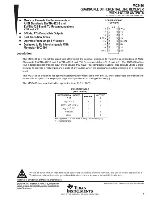
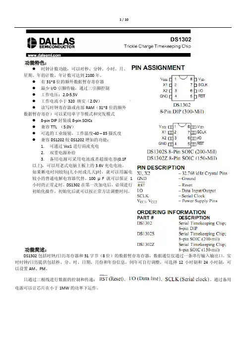
UC2848UC3848FEATURES•Practical Primary Side Control of Isolated Power Supplies with DC Control of Secondary Side Current •Accurate Programmable Maximum Duty Cycle Clamp•Maximum Volt-Second Product Clamp to Prevent Core Saturation •Practical Operation Up to 1MHz •High Current (2A Pk) Totem Pole Output Driver•Wide Bandwidth (8MHz) Current Error Amplifier•Under Voltage Lockout Monitors VCC,VIN and VREF•Output Active Low During UVLO •Low Startup Current (500µA)•Precision 5V Reference (1%)The UC3848family of PWM control ICs makes primary side average current mode control practical for isolated switching converters.Average current mode control in-sures that both cycle by cycle peak switch current and maximum average inductor current are well defined and will not run away in a short circuit situation.The UC3848can be used to control a wide variety of converter topolo-gies.In addition to the basic functions required for pulse width modulation,the UC3848implements a patented tech-nique of sensing secondary current in an isolated buck derived converter from the primary side.A current wave-form synthesizer monitors switch current and simulates the inductor current down slope so that the complete cur-rent waveform can be constructed on the primary side without actual secondary side measurement.This infor-mation on the primary side allows for full DC control of output current.The UC3848circuitry includes a precision reference,a wide bandwidth error amplifier for average current con-trol,an oscillator to generate the system clock,latching PWM comparator and logic circuits,and a high current output driver.The current error amplifier easily interfaces with an optoisolator from a secondary side voltage sens-ing circuit.A full featured undervoltage lockout (UVLO)circuit is con-tained in the UC3848.UVLO monitors the supply voltage to the controller (VCC),the reference voltage (VREF),and the input line voltage (VIN).All three must be good before soft start commences.If either VCC or VIN is low,the supply current required by the chip is only 500µA and the output is actively held low.Two on board protection features set controlled limits to prevent transformer core saturation.Input voltage is mon-itored and pulse width is constrained to limit the maxi-mum volt-second product applied to the transformer.A unique patented technique limits maximum duty cycle within 3% of a user programmed value.These two features allow for more optimal use of trans-formers and switches,resulting in reduced system size and cost.Patents embodied in the UC3848belong to Lambda Electronics Incorporated and are licensed for use in ap-plications employing these devices.DESCRIPTIONAverage Current Mode PWM ControllerSupply Voltage (Pin 15). . . . . . . . . . . . . . . . . . . . . . . . . . . .22V Output Current, Source or Sink (Pin 14)DC . . . . . . . . . . . . . . . . . . . . . . . . . . . . . . . . . . . . . . . . .0.5A Pulse (0.5s). . . . . . . . . . . . . . . . . . . . . . . . . . . . . . . . 2.2A Power Ground to Ground (Pin 1 to Pin 13). . . . . . . . . . .±0.2V Analog Input Voltages(Pins 3, 4, 7, 8, 12, 16). . . . . . . . . . . . . . . . . . . . .–0.3 to 7V Analog Input Currents, Source or Sink(Pins 3, 4, 7, 8, 11, 12, 16). . . . . . . . . . . . . . . . . . . . . .1mAAnalog Output Currents, Source or Sink (Pins 5 & 10). . .5mA Power Dissipation at TA = 60°C. . . . . . . . . . . . . . . . . . . . . .1W Storage Temperature Range . . . . . . . . . . . . . . .−65°C to +150°C Lead Temperature (Soldering 10 seconds). . . . . . . . . .+300°CNotes:All voltages are with respect to ground (DIL and SOIC Pin 1).Currents are positive into the specified terminal.Pin numbers refer to the 16pin DIL and SOIC packages.Consult Packaging Section of Databook for thermal limitations and considerations of packages.ABSOLUTE MAXIMUM RATINGSELECTRICAL CHARACTERISTICS:Unless otherwise stated, all specifications are over the junction temperature rangeof −55°C to +125°C for the UC1848,−40°C to +85°C for the UC2848, and 0°C to +70°C for the UC3848. Test conditions are: VCCCONNECTION DIAGRAMSELECTRICAL CHARACTERISTICS:Unless otherwise stated, all specifications are over the junction temperature range of−55°C to +125°C for the UC1848,−40°C to +85°C for the UC2848, and 0°C to +70°C for the UC3848. Test conditions are: VCC = 12V, CT = 400pF, CI = 100pF, IOFF = 100µA, CDC = 100nF, Cvs = 100pF, and Ivs = 400µA, T A= T J.PARAMETER TEST CONDITIONS MIN TYP MAX UNITS OscillatorFrequency T A= 25°C240250260kHz235265kHz Ramp Amplitude 1.5 1.65 1.8V Duty Cycle ClampMax Duty Cycle V(D MAX) = 0.75•V REF73.576.579.5% Volt Second ClampMax On Time9001100ns VCC ComparatorTurn-on Threshold1314V Turn-off Threshold910V Hysteresis 2.53 3.5V UV ComparatorTurn-on Threshold 4.1 4.35 4.6V R HYSTERESIS Vuv = 4.2V7790103kΩReferenceVREF T A= 25°C 4.955 5.05V0<I O<10mA, 12<VCC<20 4.93 5.07V Line Regulation12 < V CC< 20V415mV Load Regulation0 < I O< 10mA315mV Short Circuit Current V REF= 0V305070mA Output StageRise & Fall Time (Note 1)Cl = 1nF2045ns Output Low Saturation I O= 20mA0.250.4VI O= 200mA 1.2 2.2VOutput High Saturation I O= -200mA 2.0 3.0V UVLO Output Low Saturation I O= 20mA0.8 1.2VI CCI START VCC = 12V0.20.4mAI CC(pre-start)VCC = 15V, V(UV) = 00.51mAI CC(run)2226mA Note 1: Guaranteed by design.Under Voltage LockoutThe Under Voltage Lockout block diagram is shown in Fig1.The VCC comparator monitors chip supply voltage. Hysteretic thresholds are set at13V and10V to facilitate off-line applications.If the VCC comparator is low,ICC is low (<500µA) and the output is low.The UV comparator monitors input line voltage(V IN).A pair of resistors divides the input line to UV.Hysteretic in-put line thresholds are programmed by Rv1and Rv2. The thresholds areV IN(on) = 4.35V•(1 + Rv1/Rv2′) andV IN(off) = 4.35V•(1 + Rv1/Rv2) whereRv2′= Rv2||90k.The resulting hysteresis isV IN(hys) = 4.35V•Rv1 / 90k.When the UV comparator is low,I CC is low(500µA)and the output is low.APPLICATION INFORMATIONFigure 1: Under voltage lockout.Figure 2:Oscillator frequency.When both the UV and VCC comparators are high,the internal bias circuitry for the rest of the chip is activated.The CDC pin (see discussion on Maximum Duty Cycle Control and Soft Start)and the Output are held low until VREF exceeds the 4.5V threshold of the VREF com-parator.When VREF is good,control of the output driveris transferred to the PWM circuitry and CDC is allowed to charge.If any of the three UVLO comparators go low,the UVLO latch is set,the output is held low,and CDC is dis-charged.This state will be maintained until all three com-parators are high and the CDC pin is fully discharged.APPLICATION INFORMATION (cont.)OscillatorA capacitor from the CT pin to GND programs oscillator frequency,as shown in Fig. 2.Frequency is determined by:F = 1 / (10k •CT).The sawtooth wave shape is generated by a charging current of 200A and a discharge current of 1800 A.The discharge time of the sawtooth is guaranteed dead time for the output driver.If the maximum duty cycle control is defeated by connecting DMAX to VREF,the maximum duty cycle is limited by the oscillator to 90%.If an adjust-ment is required,an additional trim resistor RT from CT to Ground can be used to adjust the oscillator frequency.RT should not be less than 40k .This will allow up to a 22%decrease in frequency.Inductor Current Waveform SynthesizerAverage current mode control is a very useful technique to control the value of any current within a switching con-verter.Input current,output inductor current,switch cur-rent,diode current or almost any other current can be controlled.In order to implement average current mode control,the value of the current must be explicitly known at all times.To control output inductor current (IL)in a buck derived isolated converter,switch current provides inductor current information,but only during the on timeof the switch.During the off time,switch current drops abruptly to zero,but the inductor current actually dimin-ishes with a slope dIL/dt =–V O /L.This down slope must be synthesized in some manner on the primary side to provide the entire inductor current waveform for the con-trol circuit.The patented current waveform synthesizer (Fig.4)con-sists of a unidirectional voltage follower which forces the voltage on capacitor CI to follow the on time switch cur-rent waveform.A programmable discharge current syn-thesizes the off time portion of the waveform.ION is the input to the follower.The discharge current is pro-grammed at IOFF.The follower has a one volt offset,so that zero current corresponds to one volt at CI.The best utilization of the UC3848is to translate maximum average inductor cur-rent to a 4V signal level.Given N and Ns (the turns ratio of the power and current sense transformers),proper scaling of IL to V(CI)requires a sense resistor Rs as cal-culated from:Rs = 4V •Ns •N / IL(max).Restated,the maximum average inductor current will be limited to:IL(max) = 4V •Ns •N/Rs.IOFF and CI need to be chosen so that the ratio of dV(CI)/dt to dIL/dt is the same during switch off time as on time.Recommended nominal off current is 100 A.This requiresCI = (100µA •N •Ns •L) / (Rs •V O (nom))where L is the output inductor value and V O (nom)is the converter regulated output voltage.There are several methods to program IOFF.If accurate average current control is required during short circuit op-eration,IOFF must track output voltage.The method shown in Fig.4derives a voltage proportional to V IN •D (Duty Cycle).(In a buck converter,output voltage is pro-portional to VIN •D.)A resistively loaded diode connec-tion to the bootstrap winding yields a square wave whose amplitude is proportional to VIN and is duty cycle modu-lated by the control circuit.Averaging this waveform with a filter generates a primary side replica of secondary reg-ulated V O .A single pole filter is shown,but in practice a two or three pole filter provides better transient response.Filtered voltage is converted by ROFF to a current to theIOFF pin to control CI down slope.Figure 3:Error amplifier gain and phase response over frequency.APPLICATION INFORMATION (cont.)If the system is not sensitive to short circuit requirements,Figure 5shows the simplest method of downslope gener-ation:a single resistor (ROFF =40k)from IOFF to VREF.The discharge current is then 100µA.The disadvantage to this approach is that the synthesizer continues to gen-erate a down slope when the switch is off even during short circuit conditions.Actual inductor down slope is closer to zero during a short circuit.The penalty is that the average current is understated by an amount approxi-mately equal to the nominal inductor ripple current.Out-put short circuit is therefore higher than the designed maximum output current.A third method of generating IOFF is to add a second winding to the output inductor core (Fig.6).When the power switch is off and inductor current flows in the free wheeling diode,the voltage across the inductor is equal to the output voltage plus the diode drop.This voltage is then transformed by the second winding to the primary side of the converter.The advantages to this approach are its inherent accuracy and bandwidth.Winding the second coil on the output inductor core while maintaining the required isolation makes this a more costly solution.In the example,ROFF =V O /100µA.The 4•ROFF re-sistor is added to compensate the one volt input level of the IOFF pin.Without this compensation,a minor current foldback behavior will be observed.APPLICATION INFORMATION (cont.)Figure 5:Fixed IOFF.Figure 6:Second inductor winding generation of IOFF.Figure 4:Inductor current waveform synthesizer.Maximum Volt-Second CircuitA maximum volt-second product can be programmed by a resistor(Rvs)from VS to VIN and a capacitor(Cvs) from VS to ground(Figure7).VS is discharged while the switch is off.When the output turns on,VS is allowed to charge.Since the threshold of the VS comparator is much less than VIN,the charging profile at Vs will be es-sentially linear.If VS crosses the4.0V threshold before the PWM turns the output off,the VS comparator will turn the output off for the remainder of the cycle.The maxi-mum volt-second product isV IN•T ON(max) = 4.0V•Rvs•Cvs.Maximum Duty Cycle And Soft StartA patented technique is used to accurately program max-imum duty cycle.Programming is accomplished by a di-vider from VREF to DMAX(Fig.7).The value programmed is:D(max) = Rd1 / (Rd1 + Rd2).For proper operation,the integrating capacitor,C DC, should be larger than C DC(min)>T(osc)/80k,where T(osc)is the oscillator period.C DC also sets the soft start time constant,so values of C DC larger than minimum may be desired.The soft start time constant is approxi-mately:T(ss) = 20k•C DC.Ground PlanesThe output driver on the UC3848is capable of2A peak currents.Careful layout is essential for correct operation of the chip.A ground plane must be employed(Fig.8).A unique section of the ground plane must be designated for high di/dt currents associated with the output stage. This point is the power ground to which to PGND pin is connected.Power ground can be separated from the rest of the ground plane and connected at a single point,al-though this is not strictly necessary if the high di/dt paths are well understood and accounted for.VCC should be bypassed directly to power ground with a good high fre-quency capacitor.The sources of the power MOSFET should connect to power ground as should the return connection for input power to the system and the bulk in-put capacitor.The output should be clamped with a high current Schottky diode to both VCC and PGND.Nothing else should be connected to power ground.VREF should be bypassed directly to the signal portion of the ground plane with a good high frequency capacitor. Low esr/esl ceramic1F capacitors are recommended for both VCC and VREF.The capacitors from CT,CDC, and CI should likewise be connected to the signal ground plane.APPLICATION INFORMATION (cont.)Figure 7:Duty cycle control.UNITRODE CORPORATION7 CONTINENTAL BLVD. • MERRIMACK, NH 03054TEL. (603) 424-2410FAX (603) 424-3460Figure 8:Ground plane considerations.Figure 9:Typical application - an average current-mode isolated forward converter.IMPORTANT NOTICETexas Instruments and its subsidiaries (TI) reserve the right to make changes to their products or to discontinue any product or service without notice, and advise customers to obtain the latest version of relevant information to verify, before placing orders, that information being relied on is current and complete. All products are sold subject to the terms and conditions of sale supplied at the time of order acknowledgement, including those pertaining to warranty, patent infringement, and limitation of liability.TI warrants performance of its semiconductor products to the specifications applicable at the time of sale in accordance with TI’s standard warranty. Testing and other quality control techniques are utilized to the extent TI deems necessary to support this warranty. Specific testing of all parameters of each device is not necessarily performed, except those mandated by government requirements.CERTAIN APPLICATIONS USING SEMICONDUCTOR PRODUCTS MAY INVOLVE POTENTIAL RISKS OF DEATH, PERSONAL INJURY, OR SEVERE PROPERTY OR ENVIRONMENTAL DAMAGE (“CRITICAL APPLICATIONS”). TI SEMICONDUCTOR PRODUCTS ARE NOT DESIGNED, AUTHORIZED, OR WARRANTED TO BE SUITABLE FOR USE IN LIFE-SUPPORT DEVICES OR SYSTEMS OR OTHER CRITICAL APPLICATIONS. INCLUSION OF TI PRODUCTS IN SUCH APPLICATIONS IS UNDERSTOOD TO BE FULLY AT THE CUSTOMER’S RISK.In order to minimize risks associated with the customer’s applications, adequate design and operating safeguards must be provided by the customer to minimize inherent or procedural hazards.TI assumes no liability for applications assistance or customer product design. TI does not warrant or represent that any license, either express or implied, is granted under any patent right, copyright, mask work right, or other intellectual property right of TI covering or relating to any combination, machine, or process in which such semiconductor products or services might be or are used. TI’s publication of information regarding any third party’s products or services does not constitute TI’s approval, warranty or endorsement thereof.Copyright © 1999, Texas Instruments Incorporated。