完整word版,串口摄像头通信协议
- 格式:doc
- 大小:116.52 KB
- 文档页数:11
串口自定义通信协议程序【原创实用版】目录一、串口通信协议的基础知识二、自定义串口通信协议的实现方法三、温度采集器与上位机串口通信协议的设计实例四、自定义串口通信协议的应用优势与局限性正文一、串口通信协议的基础知识串口通信协议是一种基于串行通信的数据传输方式。
与并行通信相比,串口通信协议具有线路简单、成本低的优点。
在电子设备之间进行数据传输时,常常使用串口通信协议。
在串口通信中,数据是逐个比特按顺序进行传输的。
发送方将数据字符从并行转换为串行,按位发送给接收方。
接收方收到串行数据后,再将其转换为并行数据。
这种通信方式在仅使用一根信号线的情况下完成数据传输,具有线路简单、成本低的优点。
但是,由于串口通信是按位进行的,因此传输速度较慢,且容易受到噪声干扰。
二、自定义串口通信协议的实现方法自定义串口通信协议的实现方法主要包括以下几个步骤:1.选择合适的硬件层通信协议。
常见的硬件层通信协议有 RS-232、RS-485 等。
选择合适的通信协议需要考虑通信距离、通信速率、抗干扰能力等因素。
2.设计数据帧格式。
数据帧格式包括起始符、地址符、数据长度、数据内容、校验和、结束符等。
起始符用于指示数据帧的开始,地址符用于指示数据帧的地址,数据长度用于指示数据帧的数据内容长度,数据内容用于存储实际的数据信息,校验和用于检验数据传输的正确性,结束符用于指示数据帧的结束。
3.编写下位机程序。
下位机程序主要负责发送和接收数据,实现硬件层通信协议。
在编写下位机程序时,需要考虑数据帧的组装、发送、接收、解析等方面。
4.编写上位机程序。
上位机程序主要负责与下位机进行通信,实现数据采集、控制等功能。
在编写上位机程序时,需要考虑数据帧的解析、数据处理、控制指令的发送等方面。
三、温度采集器与上位机串口通信协议的设计实例假设我们需要设计一个温度采集器与上位机之间的串口通信协议,用于实现温度采集数据上传和上位机控制每路温度测量通道的开启功能。
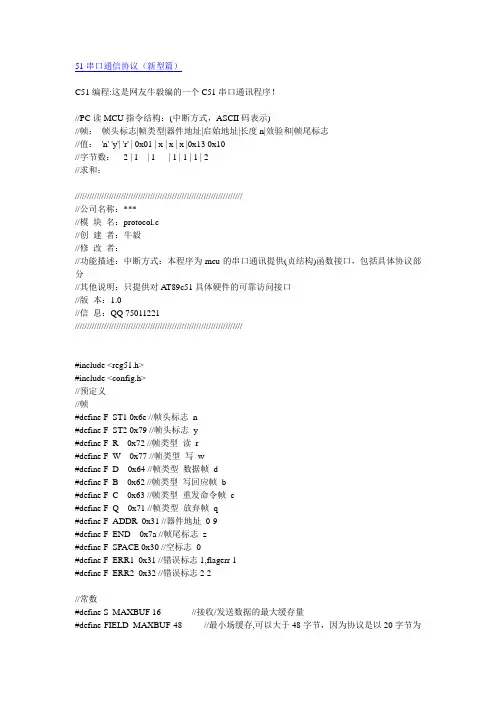
51串口通信协议(新型篇)C51编程:这是网友牛毅编的一个C51串口通讯程序!//PC读MCU指令结构:(中断方式,ASCII码表示)//帧:帧头标志|帧类型|器件地址|启始地址|长度n|效验和|帧尾标志//值: 'n' 'y'| 'r' | 0x01 | x | x | x |0x13 0x10//字节数: 2 | 1 | 1 | 1 | 1 | 1 | 2//求和:///////////////////////////////////////////////////////////////////////公司名称:***//模块名:protocol.c//创建者:牛毅//修改者://功能描述:中断方式:本程序为mcu的串口通讯提供(贞结构)函数接口,包括具体协议部分//其他说明:只提供对A T89c51具体硬件的可靠访问接口//版本:1.0//信息:QQ 75011221/////////////////////////////////////////////////////////////////////#include <reg51.h>#include <config.h>//预定义//帧#define F_ST1 0x6e //帧头标志n#define F_ST2 0x79 //帧头标志y#define F_R 0x72 //帧类型读r#define F_W 0x77 //帧类型写w#define F_D 0x64 //帧类型数据帧d#define F_B 0x62 //帧类型写回应帧b#define F_C 0x63 //帧类型重发命令帧c#define F_Q 0x71 //帧类型放弃帧q#define F_ADDR 0x31 //器件地址0-9#define F_END 0x7a //帧尾标志z#define F_SPACE 0x30 //空标志0#define F_ERR1 0x31 //错误标志1,flagerr 1#define F_ERR2 0x32 //错误标志2 2//常数#define S_MAXBUF 16 //接收/发送数据的最大缓存量#define FIELD_MAXBUF 48 //最小场缓存,可以大于48字节,因为协议是以20字节为#define communicationing P1_7 //正在通讯(1)标志#define ERRFRAME_MAX 5 //连续NOFRAME_CNT次帧不正确#define ERR_NOCNTMAX_RESEND if(++errframe_cnt<=ERRFRAME_MAX)resend_frame(); else errframe_cnt=communicationing=0;//若超过ERRFRAME_MAX 次则令通讯停止ERR_NOCNTMAX_RESEND//public 变量unsigned char databuf[FIELD_MAXBUF],errframe_cnt;//函数///////////////////////////////////////////////////////////////////////函数名:send()//功能描述:向串口发送一个字符//函数说明://调用函数://全局变量://输入:ch-要发送的ASCII字符//返回:无//设计者:牛毅//修改者://版本://///////////////////////////////////////////////////////////////////void send(unsigned char ch){SBUF=ch;while(TI==0);TI=0;}///////////////////////////////////////////////////////////////////////函数名:receive()//功能描述:从串口接收一个字符//函数说明://调用函数://全局变量://输入:无//返回:一个ASCII字符//设计者:牛毅//修改者://版本://///////////////////////////////////////////////////////////////////unsigned char receive(void){RI=0;return SBUF;}///////////////////////////////////////////////////////////////////////函数名:CharToHex()//功能描述:把ASCII字符转换为16进制//函数说明://调用函数://全局变量://输入:ASCII字符//返回:16进制//设计者:牛毅//修改者://版本:///////////////////////////////////////////////////////////////////// unsigned char CharToHex(unsigned char bChar) {if((bChar>=0x30)&&(bChar<=0x39))bChar -= 0x30;else if((bChar>=0x41)&&(bChar<=0x46))//大写字母bChar -= 0x37;else if((bChar>=0x61)&&(bChar<=0x66))//小写字母bChar -= 0x57;else bChar = 0xff;return bChar;}///////////////////////////////////////////////////////////////////////函数名:HexToChar()//功能描述:把16进制转换为ASCII字符//函数说明://调用函数://全局变量://输入:16进制//返回:ASCII字符//设计者:牛毅//修改者://版本:///////////////////////////////////////////////////////////////////// unsigned char HexToChar(unsigned char bHex) {if((bHex>=0)&&(bHex<=9))bHex += 0x30;else if((bHex>=10)&&(bHex<=15))//大写字母bHex += 0x37;else bHex = 0xff;return bHex;}///////////////////////////////////////////////////////////////////////函数名:com_int()//功能描述:初始化串口//函数说明:默认其他参数为[baud_rate],n,8,1//调用函数://全局变量://输入:baud_rate 波特率//返回:无//设计者:牛毅//修改者://版本://///////////////////////////////////////////////////////////////////void com_init(unsigned int baud_rate){EA=1;ES=1;//ET1=1;SCON = 0x50; /* 0x52;//SCON */TMOD = 0x20; /*0x20;// TMOD */TCON = 0x60; /*0x60;// TCON */PCON=PCON&0x7f;switch(baud_rate){ //波特率设置case 1200:TL1=0xe8;TH1=0Xe8;break; //1200case 2400:TL1=0xf4;TH1=0Xf4;break; //2400case 4800:TL1=0xfa;TH1=0Xfa;break; //4800case 9600:TL1=0xfd;TH1=0Xfd;break; //9600case 19200:PCON=PCON|0x80;TL1=0xfd;TH1=0Xfd;break; //19200 case 38400:PCON=PCON|0x80;TL1=0xfe;TH1=0Xfe;break; //38400 default:TL1=0xfd;TH1=0Xfd;break;//9600}}//函数名:resend_frame()//功能描述:发送重发帧//函数说明:通知PC重发//调用函数://全局变量://输入:无//返回:无//设计者:牛毅//修改者://版本:///////////////////////////////////////////////////////////////////// void resend_frame(void){send(F_ST1);send(F_ST2);send(F_C);send(F_SPACE);send(F_SPACE);//发送效验和send(F_END);}///////////////////////////////////////////////////////////////////// //函数名:quit_frame()//功能描述:发送放弃帧//函数说明:通知PC放弃通讯//调用函数://全局变量://输入:无//返回:无//设计者:牛毅//修改者://版本:///////////////////////////////////////////////////////////////////// void quit_frame(void){send(F_ST1);send(F_ST2);send(F_Q);send(F_ERR1);send(F_ERR1);//发送效验和send(F_END);}//函数名:com_int()//功能描述:串口中断//函数说明://调用函数://全局变量://输入:无//返回:无//设计者:牛毅//修改者://版本://///////////////////////////////////////////////////////////////////void com_int()interrupt 4{unsigned char i,csaddr,clen,csum,tempbuf[S_MAXBUF]; csum=0;if(receive()==F_ST1){//是侦if(receive()==F_ST2){//头判断完communicationing=1;//设置通讯状态为正常即启动通讯switch(receive()){case F_R://是读指令帧rif(receive()==F_ADDR){P1_2=!P1_2;//地址正确csaddr=CharToHex(receive())<<4;csaddr+=CharToHex(receive());clen=CharToHex(receive())<<4;clen+=CharToHex(receive()); csum=csaddr+clen;i=CharToHex(receive())<<4;i+=CharToHex(receive());if(i==csum){//效验和正确if(receive()==F_END){//结束标志正确//开始发送数据帧csum=0;send(F_ST1);send(F_ST2);send(F_D);send(HexToChar((clen&0xf0)>>4));send(HexToChar(clen&0x0f));csum+=clen;for(i=0;i<clen;i++)send(HexToChar((databuf[i+csaddr]&0xf0)>>4)); send(HexToChar(databuf[i+csaddr]&0x0f));csum+=databuf[i+csaddr];}//if(csum>127)csum-=128;send(HexToChar((csum&0xf0)>>4));send(HexToChar(csum&0x0f));send(F_END);//发送数据帧完毕P1_0=!P1_0;}else{ERR_NOCNTMAX_RESEND break;}//结束标志错误}else{ERR_NOCNTMAX_RESENDbreak;}//效验和错误}//地址不正确break;case F_W://是PC写指令帧wif(receive()==F_ADDR){//地址正确csaddr=CharToHex(receive())<<4;csaddr+=CharToHex(receive());clen=CharToHex(receive())<<4;clen+=CharToHex(receive());csum=csaddr+clen;for(i=0;i<clen;i++){tempbuf[i+csaddr]=CharToHex(receive())<<4; tempbuf[i+csaddr]+=CharToHex(receive());csum+=tempbuf[i+csaddr];}i=CharToHex(receive())<<4;i+=CharToHex(receive()); if(csum!=i){ERR_NOCNTMAX_RESEND break;}//效验和错误if(F_END!=receive())ERR_NOCNTMAX_RESENDbreak;}//结束标志错误for(i=csaddr;i<clen+csaddr;i++)databuf[i-csaddr]=tempbuf[i-csaddr];//正确则保存数据}//从PC获得数据写完毕//开始发送写回应帧send(F_ST1);send(F_ST2);send(F_B);send(F_SPACE);send(F_SPACE);//发送效验和send(F_END);//写回应帧发送完毕P1_1=!P1_1;break;case F_Q://检测接收放弃帧csaddr=receive();csum+=csaddr;//csaddr兼做放弃帧码标志if(csaddr!=F_ERR1 && csaddr!=F_ERR2){ERR_NOCNTMAX_RESEND break;}if(csum!=receive()){ERR_NOCNTMAX_RESENDbreak;}if(F_END!=receive()){ERR_NOCNTMAX_RESENDbreak;}communicationing=0;//出错退出通讯break;default:resend_frame();//要求从发}}//忽略}//忽略if(!communicationing)quit_frame();//调用放弃帧,通知PC 放弃通讯}///////////////////////////////////////////////////////////////////主函数/////////////////////////////////////////////////////////////////void main(void){unsigned char i;for (i=0;i<FIELD_MAXBUF;i++) databuf=i+0x30;com_init(38400);while(1){/*可以处理非串口任务*/}。
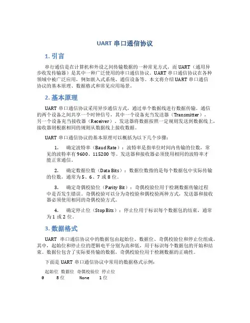
UART串口通信协议1. 引言串行通信是在计算机和外设之间传输数据的一种常见方式,而UART(通用异步收发传输器)是其中一种广泛使用的串口通信协议。
UART串口通信协议在各种领域中被广泛应用,例如嵌入式系统、通信设备等。
本文将介绍UART串口通信协议的基本原理、数据格式和常见应用场景。
2. 基本原理UART串口通信协议采用异步通信方式,通过单个数据线进行数据传输。
通信的两个设备之间共享一个时钟信号,其中一个设备充当发送器(Transmitter),另一个设备充当接收器(Receiver)。
发送器将数据按照一定规则发送到数据线上,接收器则根据相同的规则从数据线上接收数据。
UART串口通信协议的基本原理可以概括为以下几个步骤:1.确定波特率(Baud Rate):波特率是指单位时间内传输的位数,常见的波特率有9600、115200等。
发送器和接收器必须使用相同的波特率才能正常通信。
2.确定数据位数(Data Bits):数据位数指的是每个数据包中实际传输的位数,通常为5、6、7或8位。
3.确定奇偶校验位(Parity Bit):奇偶校验位用于检测数据传输过程中是否发生错误。
奇偶校验可以分为奇校验和偶校验两种方式,发送器和接收器必须使用相同的奇偶校验方式。
4.确定停止位(Stop Bits):停止位用于标识每个数据包的结束,通常为1或2位。
3. 数据格式UART串口通信协议中的数据包由起始位、数据位、奇偶校验位和停止位组成。
其中,起始位和停止位的逻辑电平分别为高和低,用于标识每个数据包的开始和结束。
数据位包含了实际要传输的数据,奇偶校验位用于检测数据的正确性。
下面是UART串口通信协议中常用的数据格式示例:起始位数据位奇偶校验位停止位0 8位 None 1位在以上示例中,数据位为8位,没有奇偶校验位,停止位为1位。
这种数据格式在许多UART串口通信应用中被广泛使用。
4. 应用场景UART串口通信协议在许多领域中得到了广泛应用,以下是一些常见的应用场景:4.1 嵌入式系统在嵌入式系统中,UART串口通信协议用于与外部设备进行通信。
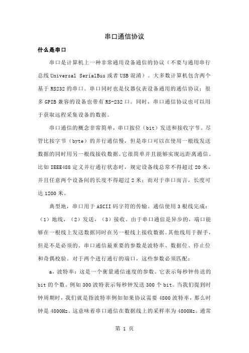
串口通信协议什么是串口串口是计算机上一种非常通用设备通信的协议(不要与通用串行总线Universal SerialBus或者USB混淆)。
大多数计算机包含两个基于RS232的串口。
串口同时也是仪器仪表设备通用的通信协议;很多GPIB兼容的设备也带有RS-232口。
同时,串口通信协议也可以用于获取远程采集设备的数据。
串口通信的概念非常简单,串口按位(bit)发送和接收字节。
尽管比按字节(byte)的并行通信慢,但是串口可以在使用一根线发送数据的同时用另一根线接收数据。
它很简单并且能够实现远距离通信。
比如IEEE488定义并行通行状态时,规定设备线总常不得超过20米,并且任意两个设备间的长度不得超过2米;而对于串口而言,长度可达1200米。
典型地,串口用于ASCII码字符的传输。
通信使用3根线完成:(1)地线,(2)发送,(3)接收。
由于串口通信是异步的,端口能够在一根线上发送数据同时在另一根线上接收数据。
其他线用于握手,但是不是必须的。
串口通信最重要的参数是波特率、数据位、停止位和奇偶校验。
对于两个进行通行的端口,这些参数必须匹配:a,波特率:这是一个衡量通信速度的参数。
它表示每秒钟传送的bit的个数。
例如300波特表示每秒钟发送300个bit。
当我们提到时钟周期时,我们就是指波特率例如如果协议需要4800波特率,那么时钟是4800Hz。
这意味着串口通信在数据线上的采样率为4800Hz。
通常电话线的波特率为14400,28800和36600。
波特率可以远远大于这些值,但是波特率和距离成反比。
高波特率常常用于放置的很近的仪器间的通信,典型的例子就是GPIB设备的通信。
b,数据位:这是衡量通信中实际数据位的参数。
当计算机发送一个信息包,实际的数据不会是8位的,标准的值是5、7和8位。
如何设置取决于你想传送的信息。
比如,标准的ASCII码是0~127(7位)。
扩展的ASCII码是0~255(8位)。
如果数据使用简单的文本(标准ASCII码),那么每个数据包使用7位数据。
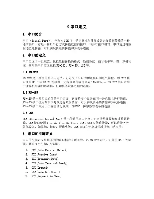
9串口定义1. 串口简介串口(Serial Port),也称为COM口,是计算机与外部设备进行数据传输的一种通信接口。
它是一种以串行方式传输数据的接口,与并行接口相对。
串口通过将数据逐位地传输,可以实现长距离传输和多设备连接。
2. 串口的定义串口定义了一组规范,包括数据传输的格式、通信协议、信号电平等。
在计算机领域,常用的串口定义包括RS-232、RS-485、USB等。
2.1 RS-232RS-232是一种常用的串口定义,它定义了串口的物理接口和电气特性。
RS-232接口使用DB-9或DB-25连接器,支持最高传输速率为115200bps。
RS-232接口常用于计算机与调制解调器、打印机等设备之间的连接。
2.2 RS-485RS-485是一种多点通信的串口定义,它支持多个设备在同一条总线上进行通信。
RS-485接口使用两根信号线进行数据传输,可以实现长距离传输和多设备连接。
RS-485接口常用于工业自动化领域,如PLC、传感器等设备的连接。
2.3 USBUSB(Universal Serial Bus)是一种通用串口定义,它支持热插拔和高速数据传输。
USB接口使用Type-A、Type-B、Micro-USB、USB-C等连接器,可以连接各种外部设备,如鼠标、键盘、摄像头等。
USB接口在计算机领域得到广泛应用。
3. 串口的引脚定义串口的引脚定义根据不同的串口标准有所差异。
以RS-232为例,它使用DB-9连接器,共有9个引脚,分别是:1.DCD(Data Carrier Detect)2.RXD(Receive Data)3.TXD(Transmit Data)4.DTR(Data Terminal Ready)5.GND(Ground)6.DSR(Data Set Ready)7.RTS(Request to Send)8.CTS(Clear to Send)9.RI(Ring Indicator)4. 串口的数据传输格式串口的数据传输格式包括数据位、停止位、校验位等。
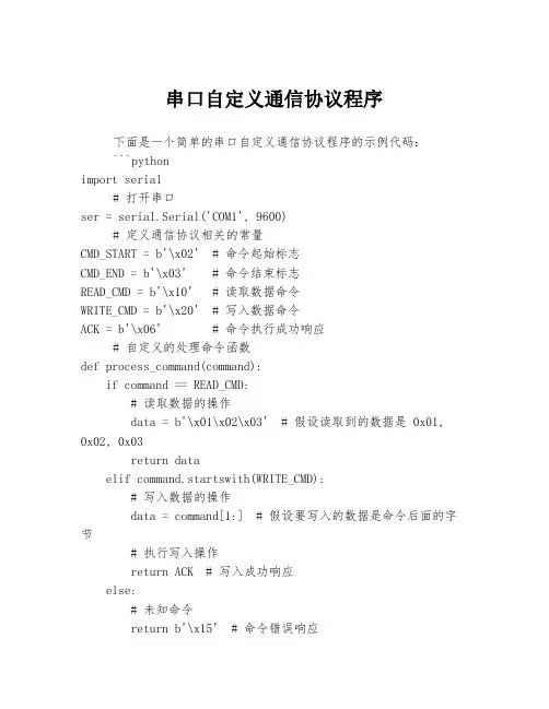
串口自定义通信协议程序下面是一个简单的串口自定义通信协议程序的示例代码:```pythonimport serial# 打开串口ser = serial.Serial('COM1', 9600)# 定义通信协议相关的常量CMD_START = b'\x02' # 命令起始标志CMD_END = b'\x03' # 命令结束标志READ_CMD = b'\x10' # 读取数据命令WRITE_CMD = b'\x20' # 写入数据命令ACK = b'\x06' # 命令执行成功响应# 自定义的处理命令函数def process_command(command):if command == READ_CMD:# 读取数据的操作data = b'\x01\x02\x03' # 假设读取到的数据是 0x01, 0x02, 0x03return dataelif command.startswith(WRITE_CMD):# 写入数据的操作data = command[1:] # 假设要写入的数据是命令后面的字节# 执行写入操作return ACK # 写入成功响应else:# 未知命令return b'\x15' # 命令错误响应while True:# 读取串口数据data = ser.read_until(CMD_END)# 解析命令if data.startswith(CMD_START) and data.endswith(CMD_END): command = data[1:-1]# 处理命令并返回响应response = process_command(command)# 发送响应数据ser.write(CMD_START + response + CMD_END)```这是一个基于Python的串口通信程序,使用了自定义的通信协议。
RS485串口通信原理一、RS485串口通信协议原理与特点1.电平传输特点:RS485通信使用差分信号进行传输,即通过正负两个信号线分别传输高低电平,抵消了电磁干扰对信号的影响,提高了传输的抗干扰性能。
2.单主多从:RS485通信存在一个主机和多个从机,主机负责向从机发送指令,而从机接收指令并返回数据。
3.半双工通信:RS485通信只能在一个方向上进行通信,即由主机发送指令到从机,或者从机发送数据到主机,无法同时进行双向通信。
4.多层级网络:RS485通信可以通过多级网络实现跨越更长的距离和更多设备的通信,每级网络之间通过中继器进行连接。
二、RS485通信方式1.同步方式:同步通信是指主机和从机之间在时钟方面进行同步的通信方式。
主机发送时钟信号给从机,从机根据时钟信号进行数据发送和接收,确保数据的完整性和准确性。
同步通信的优点是数据传输速度快,但对时钟同步要求较高。
2.异步方式:异步通信是指主机和从机之间不需要进行时钟同步的通信方式。
主机和从机之间通过控制字符进行数据传输和接收,可以自由控制数据传输速度和时钟精度。
异步通信的优点是适用性广,不需要严格的时钟同步,但数据传输速度较慢。
三、RS485通信协议1.物理层:RS485通信采用差分传输的物理层信号,正负两个信号线分别传输高低电平数据。
通信时需进行数据电平转换,将逻辑高电平和逻辑低电平转换为物理层的高电平和低电平信号。
2.数据链路层:RS485通信的数据链路层采用帧结构进行数据的传输和接收。
数据帧包括起始位、数据位、校验位和停止位。
起始位用于表示数据帧的开始,数据位用于存储实际传输的数据,校验位用于验证数据的准确性,停止位用于表示数据帧的结束。
四、RS485通信应用场景1.工业自动化控制:RS485通信可用于PLC控制系统、工业仪表传感器等设备之间的通信,可实现工业自动化控制和数据采集。
2.楼宇自控系统:RS485通信可用于楼宇自控系统中的空调、照明、电梯等设备之间的通信,实现楼宇设备的集中控制和管理。
电梯监控系统串口2数据输出通信协议一、概述:电梯监控系统的电脑主机可扩展增加一个串口,这个串口可由电梯监控系统软件上设置是否输出数据,输出的数据为实时所采集到的整个网络的各个电梯的数据。
并且数据按一定的规则和格式定义。
这就是下面所述的电梯监控系统串口2的数据输出的通信协议。
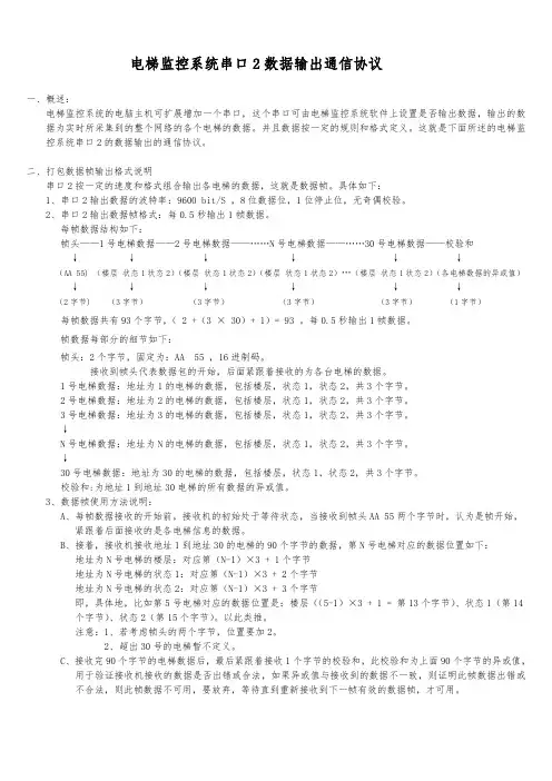
二、打包数据帧输出格式说明串口2按一定的速度和格式组合输出各电梯的数据,这就是数据帧。
具体如下:1、串口2输出数据的波特率:9600 bit/S ,8位数据位,1位停止位,无奇偶校验。
2、串口2输出数据帧格式:每0.5秒输出1帧数据。
每帧数据结构如下:帧头——1号电梯数据——2号电梯数据——……N号电梯数据——……30号电梯数据——校验和↓↓↓↓↓↓(AA 55) (楼层状态1状态2)(楼层状态1状态2)(楼层状态1状态2)…(楼层状态1状态2)(各电梯数据的异或值)↓↓↓↓↓↓(2字节) (3字节)(3字节)(3字节)(3字节)(1字节)每帧数据共有93个字节,( 2 +(3 × 30)+ 1)= 93 。
每0.5秒输出1帧数据。
帧数据每部分的细节如下:帧头:2个字节,固定为:AA 55 ,16进制码。
接收到帧头代表数据包的开始,后面紧跟着接收的为各台电梯的数据。
1号电梯数据:地址为1的电梯的数据,包括楼层,状态1,状态2,共3个字节。
2号电梯数据:地址为2的电梯的数据,包括楼层,状态1,状态2,共3个字节。
3号电梯数据:地址为3的电梯的数据,包括楼层,状态1,状态2,共3个字节。
↓N号电梯数据:地址为N的电梯的数据,包括楼层,状态1,状态2,共3个字节。
↓30号电梯数据:地址为30的电梯的数据,包括楼层,状态1,状态2,共3个字节。
校验和:为地址1到地址30电梯的所有数据的异或值。
3、数据帧使用方法说明:A、每帧数据接收的开始前,接收机的初始处于等待状态,当接收到帧头AA 55两个字节时,认为是帧开始,紧跟着后面接收的是各电梯信息的数据。
232通信协议1. 简介232通信协议是一种常见的串行通信协议,用于在计算机和外部设备之间进行数据传输。
它是一种简单而可靠的通信方式,广泛应用于各种领域,如工业控制、仪器仪表、通信设备等。
2. 协议结构232通信协议采用点对点的通信方式,由发送方和接收方两个角色组成。
数据在发送方和接收方之间通过串行线路进行传输,以字节为单位进行交换。
2.1 帧结构每个数据帧由起始位、数据位、校验位和停止位组成。
以下是一个典型的数据帧结构示例:起始位数据位校验位停止位0 0100111 1 1•起始位:用于标识数据帧的开始。
•数据位:包含要传输的数据内容。
•校验位:用于检测数据的完整性和准确性。
•停止位:用于标识数据帧的结束。
2.2 通信速率232通信协议支持多种通信速率,常见的速率有9600、19200、38400等。
通信速率越高,数据传输的速度越快,但也需要更高的硬件要求和稳定性。
3. 数据传输232通信协议通过串行线路将数据从发送方传输到接收方。
数据在传输过程中,经过起始位、数据位、校验位和停止位的处理,以确保数据的准确性和完整性。
3.1 数据编码在232通信协议中,数据通过ASCII码进行编码。
每个字符都有一个对应的ASCII码,通过将ASCII码转换为二进制形式,可以在串行线路上传输。
3.2 数据传输方式232通信协议支持两种数据传输方式:单向传输和双向传输。
•单向传输:数据只能从发送方传输到接收方,接收方无法向发送方发送数据。
•双向传输:发送方和接收方可以相互传输数据。
4. 应用领域232通信协议广泛应用于各种领域,如工业控制、仪器仪表、通信设备等。
4.1 工业控制在工业控制领域,232通信协议常用于PLC(可编程逻辑控制器)和人机界面(HMI)之间的通信。
通过232通信协议,PLC可以向HMI发送控制指令,实现对工业设备的监控和控制。
4.2 仪器仪表在仪器仪表领域,232通信协议常用于仪器设备和计算机之间的数据传输。
uart串口通信协议UART串口通信协议。
UART(Universal Asynchronous Receiver/Transmitter)是一种通用的异步串行通信接口,广泛应用于各种嵌入式系统和外设设备之间的通信。
在本文中,我们将介绍UART串口通信协议的基本原理、通信流程以及常见问题解决方法。
1. 基本原理。
UART串口通信是一种点对点的通信方式,由发送端和接收端组成。
通信的基本单位是一个字节(8位),包括起始位、数据位、校验位和停止位。
在通信开始之前,发送端和接收端必须约定好通信的波特率、数据位、校验位和停止位等参数,以确保通信的准确性和稳定性。
2. 通信流程。
UART串口通信的流程一般包括以下几个步骤:a. 发送端准备好要发送的数据,并将数据写入UART发送缓冲区。
b. UART发送端根据约定的参数,将数据以一定的波特率发送出去,包括起始位、数据位、校验位和停止位。
c. 数据经过传输介质(如串口线)传输到接收端。
d. UART接收端接收到数据后,将数据读取到接收缓冲区。
e. 接收端根据约定的参数,对接收到的数据进行解析和处理。
3. 常见问题解决方法。
在实际应用中,UART串口通信可能会遇到一些常见问题,如数据丢失、波特率不匹配、数据格式错误等。
针对这些问题,我们可以采取一些解决方法:a. 数据丢失,可以通过增加数据缓冲区的大小、提高处理数据的速度等方式来解决。
b. 波特率不匹配,发送端和接收端的波特率必须一致,否则会导致数据传输错误,可以通过修改通信参数来解决。
c. 数据格式错误,检查数据位、校验位和停止位等参数是否设置正确,确保发送端和接收端的参数一致。
总结。
通过本文的介绍,我们了解了UART串口通信协议的基本原理、通信流程以及常见问题解决方法。
在实际应用中,我们需要根据具体的需求和场景来合理选择通信参数,并严格遵守通信协议,以确保通信的稳定和可靠。
希望本文能对您有所帮助,谢谢阅读!。
串口通信协议文件后缀(原创版)目录1.串口通信协议简介2.串口通信协议文件的后缀3.常见串口通信协议文件后缀介绍4.如何选择合适的串口通信协议文件后缀正文【1.串口通信协议简介】串口通信协议,又称为串行通信协议,是一种数据传输方式。
它是指在数据传输过程中,数据是逐个比特按顺序进行传输的。
发送方将数据字符从并行转换为串行,按位发送给接收方。
接收方收到串行数据后,再将其转换为并行数据。
这种通信方式在电子设备、计算机外设、通信设备等领域有广泛的应用。
【2.串口通信协议文件的后缀】串口通信协议文件的后缀通常表示文件的类型和格式。
常见的后缀有.txt、.csv、.xml、.json 等。
这些后缀分别代表了纯文本、逗号分隔值、可扩展标记语言、JavaScript 对象表示法等不同类型的文件。
【3.常见串口通信协议文件后缀介绍】-.txt:纯文本格式,适用于存储简单的串口通信协议数据。
该格式文件可被大多数文本编辑器打开和编辑。
-.csv:逗号分隔值格式,适用于存储结构化数据。
在串口通信协议中,数据通常以逗号分隔的形式存储在文件中。
-.xml:可扩展标记语言格式,适用于存储复杂的数据结构。
在串口通信协议中,数据可以以树形结构存储,方便数据的管理和查询。
-.json:JavaScript 对象表示法格式,适用于存储键值对数据。
在串口通信协议中,数据可以以 JSON 对象的形式存储,方便程序间的数据交换。
【4.如何选择合适的串口通信协议文件后缀】选择合适的串口通信协议文件后缀,需要根据实际应用场景和需求来确定。
以下是一些建议:- 如果数据量较小且结构简单,可以选择.txt 格式。
- 如果数据结构较为复杂,可以选择.xml 或.json 格式。
- 如果需要进行数据交换或共享,可以选择.json 格式,因为 JSON 格式的数据易于程序间的交换和解析。
温馨小提示:本文主要介绍的是关于串口通信方式规约的文章,文章是由本店铺通过查阅资料,经过精心整理撰写而成。
文章的内容不一定符合大家的期望需求,还请各位根据自己的需求进行下载。
本文档下载后可以根据自己的实际情况进行任意改写,从而已达到各位的需求。
愿本篇串口通信方式规约能真实确切的帮助各位。
本店铺将会继续努力、改进、创新,给大家提供更加优质符合大家需求的文档。
感谢支持!(Thank you for downloading and checking it out!)阅读本篇文章之前,本店铺提供大纲预览服务,我们可以先预览文章的大纲部分,快速了解本篇的主体内容,然后根据您的需求进行文档的查看与下载。
串口通信方式规约(大纲)一、串口通信概述1.1串口通信的定义1.2串口通信的发展历程1.3串口通信的应用场景二、串口通信硬件基础2.1串行通信接口标准2.1.1RS-2322.1.2RS-4852.1.3RS-4222.2串口通信的主要硬件设备2.2.1串口芯片2.2.2串口转接器2.2.3串口服务器三、串口通信协议3.1数据格式3.1.1起始位3.1.2数据位3.1.3停止位3.1.4校验位3.2波特率与数据传输速率3.3流控制3.3.1硬件流控制3.3.2软件流控制四、串口通信编程4.1串口通信API4.1.1Windows平台下的串口通信API4.1.2Linux平台下的串口通信API4.2串口通信编程实践4.2.1串口初始化4.2.2串口数据发送与接收4.2.3串口事件处理五、串口通信应用案例分析5.1工业控制领域5.2嵌入式系统5.3网络通信领域5.4其他应用案例六、串口通信故障排查与优化6.1常见故障类型6.1.1硬件故障6.1.2软件故障6.1.3系统配置故障6.2故障排查方法6.2.1硬件检查6.2.2软件调试6.2.3系统优化6.3串口通信稳定性优化策略七、串口通信的未来发展趋势7.1新型串口通信技术7.2串口通信在物联网中的应用7.3串口通信与其他通信技术的融合一、串口通信概述1.1 串口通信的定义串口通信,又称串行通信,是一种计算机与外部设备或计算机之间的数据传输方式。
串口协议数据报文格式1. ASCII码格式:ASCII码格式是一种常见的串口通信协议,它使用可打印字符来表示数据。
每个数据字节都被转换成对应的ASCII字符发送。
通常,一个数据报文由起始位、数据位、校验位和停止位组成。
例如,一个典型的ASCII码格式的数据报文可能如下所示:起始位 + 数据位 + 校验位 + 停止位。
其中,起始位和停止位通常使用逻辑高电平表示,而数据位和校验位则使用ASCII字符进行表示。
2. 二进制格式:二进制格式是另一种常见的串口通信协议,它直接将数据以二进制形式传输。
在二进制格式中,一个数据报文通常由起始位、数据位、校验位和停止位组成。
不同于ASCII码格式,二进制格式中的数据位直接以二进制形式发送,而不是转换成可打印字符。
例如,一个典型的二进制格式的数据报文可能如下所示:起始位 + 数据位 + 校验位 + 停止位。
起始位和停止位通常使用逻辑高电平表示,而数据位和校验位则使用二进制形式。
3. 帧格式:帧格式是一种更加复杂的串口通信协议,它将数据划分为多个字段,并在数据报文中使用特定的标识符来标识每个字段。
帧格式通常包括起始标识符、地址字段、控制字段、数据字段、校验字段和结束标识符等。
起始标识符和结束标识符用于标识一个数据报文的开始和结束,地址字段用于指示数据报文的目标设备,控制字段用于指示数据报文的类型或操作,数据字段用于携带实际的数据,校验字段用于验证数据的完整性。
不同的协议可能会有不同的帧格式定义。
总之,串口协议数据报文格式可以根据具体的协议而有所不同,常见的格式包括ASCII码格式、二进制格式和帧格式等。
在实际应用中,选择合适的数据报文格式需要考虑到通信需求、数据传输效率、数据完整性和易于解析等因素。
以上是对串口协议数据报文格式的多角度全面完整的回答,希望能对你有所帮助。
串口和hlw8110的通信协议概述及解释说明1. 引言1.1 概述在现代电子设备中,串口通信协议扮演着至关重要的角色。
它是一种用于在不同设备之间进行数据传输的通信接口协议。
而hlw8110作为一款广泛应用于电力监测和管理领域的芯片,其通信协议也十分重要。
本文将详细介绍串口和hlw8110的通信协议,并对其进行概述和解释说明。
通过深入了解这两个通信协议,读者将能够更好地理解其基本原理和功能特点,从而更加有效地应用到相关领域中。
1.2 文章结构本文分为五个部分:引言、串口和hlw8110的通信协议概述、串口通信协议详解、hlw8110通信协议详解以及结论与展望。
引言部分主要介绍文章的背景,明确研究目标,并概述后续各部分内容。
串口和hlw8110的通信协议概述部分主要对串口通信和hlw8110进行简要介绍,包括它们在实际中的应用、基本原理等方面的内容。
串口通信协议详解部分将详细解释串口通信协议的帧格式、数据传输流程以及错误检测和纠错机制等关键内容。
hlw8110通信协议详解部分将深入讨论hlw8110的寄存器定义和功能说明、数据读取和写入过程分析,同时提供一些用户自定义配置示例。
最后,结论与展望部分对全文进行总结,并展望了串口和hlw8110通信协议在未来的发展方向。
1.3 目的本文的主要目的是提供一个全面且清晰的概述,以便读者能够理解和应用串口和hlw8110的通信协议。
通过阅读本文,读者将获得对这两个协议的深入了解,从而能够更好地应用它们在相关领域中。
同时,本文也为进一步研究和开发相关领域的技术提供了参考基础。
2. 串口和hlw8110的通信协议概述2.1 串口通信简介串口通信是一种通过串行传输数据的方式,它利用串行数据传输的特点,将数据位按照顺序逐个发送或接收。
串口通信具有以下特点:- 采用单一线路进行数据传输,包括一个发送线路(TX)和一个接收线路(RX)。
- 数据以二进制形式逐位传输,并且按照一定的帧结构进行组织。
rs232串口通讯—通信协议(RS232 serial communication protocol)Serial communication protocolAdd time: 2006-11-14 Author: unknown source: unknown entry: abcd200844 read times:--------------------------------------------------------------------------------The so-called communication protocol refers to an agreement between the two sides of communication. The agreement includes uniform rules for data format, synchronization mode, transmission speed, transmission step, check and error correction method, and control character definition, and the two parties must abide by it together. It is also called a communication control procedure, or a transport control procedure, that belongs to the data link layer in the seven - layer reference model of the ISO'S OSI.At present, there are two kinds of communication protocols: asynchronous protocol and synchronous protocol. There are three types of synchronization protocols: character oriented, bit oriented, and byte oriented. Among them, byte counting synchronous protocol is mainly used in DEC's network architecture.Physical interface standard1. basic tasks of serial communication interface(1) data formatting: since the CPU comes from common paralleldata, the interface circuit should have the task of data formatting under different serial communication modes. In asynchronous communication mode, the interface automatically generates start stop type frame data format. In character oriented synchronization, the interface adds synchronization characters before the data block to be transmitted.(2) string conversion: serial transfer, data is bit by bit serial transmission, and computer processing data is parallel data. Therefore, when data is sent to the data transmitter by computer, the serial data is converted into parallel number to be sent into the computer. Therefore, serial to serial conversion is an important task of serial interface circuits.(3) control the data transmission rate: the serial communication interface circuit should have the ability to select and control the data transmission rate baud rate.(4) error detection: when sending, the interface circuit automatically generates parity check bits or other parity codes for the transmitted character data. At reception, the interface circuit checks parity or other check codes of the character to determine whether a transmission error has occurred.(5) carry on TTL and EIA level conversion: CPU and terminal adopt TTL level and positive logic, they are incompatible with the level and negative logic adopted by EIA and need to convert in the interface circuit.(6) providing the signal line required by the EIA-RS-232C interface standard: when using MODEM for long distancecommunication, 9 signal lines are needed, and only 3 signal lines are needed in the near zero MODEM mode. These signal lines are provided by an interface circuit to communicate and control with the MODEM or terminal.2 、 composition of serial communication interface circuitIn order to accomplish the tasks of the serial interface, the serial communication interface circuit is generally composed of a programmable serial interface chip, a baud rate generator, a EIA and an TTL level converter, and an address decoding circuit. Among them, the serial interface chip, along with the large-scale inheritance circuit technology development, the universal synchronous (USRT) and the asynchronous (UART) interface chip kinds are more and more many, as shown in the following table. Their basic functions are similar, and they can implement most of the basic tasks of the serial communication interface mentioned above, and all of them are programmable. With these chips as the core chip of the serial communication interface circuit, the circuit structure will be relatively simple.3. physical standards for serial communicationIn order to make the computer, telephone and other communication devices communicate with each other, now has established several consistent definition and standard of serial communication, these concepts and standards are three aspects: electrical characteristics, transmission rate, signal name and interface standard.1, transmission rate: the so-called transmission rate refers to the number of bits per second, the transmission rate is often called baud rate. A standard baud rate series is specified internationally,The standard baud rate is also the most commonly used baud rate. The standard baud rate series are 110, 300, 600, 1200, 4800, 9600 and 19200. Most CRT terminals are able to work at any baud rate in the range of 110 to 9600. The printer speed is relatively slow due to mechanical transmission and the baud rate is limited, so the general serial printer at 110 baud rate, little needle type printer because of its internal buffer for larger, so you can receive printed information by up to 2400 the speed of Potter. The receive baud rate and baud rate of most interfaces can be set separately, and can be specified by programming.2, RS-232-C standard: the RS-232-C standard has made the stipulation to two aspects, namely signal level standard and control signal line definition. RS-232C uses negative logic rules of logic level, signal level and the TTL level is usually not compatible with RS-232-C, -5V ~ -15V provides for the "1", "0 rules for +5V ~ +15V". Figure 1 is the level conversion between the TTL standard and the RS-232-C standard.Figure 1Two, software protocol1.OSI protocol and TCP/IP protocolFigure 2(1) OSI agreementThe OSI seven layer reference model is not a communication standard. It only gives a stable model that does not necessarily change due to technological development, so that standards and protocols can be developed and coordinated within the scope of the model definition.The general protocol only conforms to several layers of the OSI seven - layer model, such as: EIA-RS-232-C: implements the physical layer. IBM's SDLC (synchronous data link control procedures): data link layer. ANSI's ADCCP (advanced data communication protocol): data link layer IBM BSC (binary synchronous communication protocol): data link layer. The application layer email protocol SMTP is only responsible for sending letters, and POP3 is only responsible for receiving messages.(2) TCP/IP agreementFive layer protocol is implemented.(1) physical layer: the physical layer corresponding to OSI.(2) network interface layer: data link layer similar to OSI.(3) Internet layer: the OSI model is put forward before the Internet network is used, without considering the inter network connection.(4) transport layer: the transport layer corresponding to OSI.(5) application layer: the presentation layer and application layer corresponding to OSI.2. serial communication protocolSerial communication protocol, sub synchronous protocol and asynchronous protocol.(1) asynchronous communication protocol example start stop asynchronous protocolFigure 3Features and formats:Start stop asynchronous protocol is characterized by the transfer of one character to one character, and the transfer of a character that always starts with the start bit to stop the end of the bit, and there is no fixed time interval between characters. Its format is shown in figure 3. In front of each character has a start bit (low level, logical value 0), the character itself has 5 ~ 7 data bits, then the character behind is a parity bit (or no parity bit), the last is a means, or half, or two stop, stop who is behind the indefinite length of idle bits. The stop bit and the idle bit are specified as high levels (logical values) so that the start bit must have a lower jump edge at the start.As you can see from the diagram, the format is defined orsynchronized by the start and stop bits, so it is called the start protocol. When the data is transmitted, the data is in the low position and the high position is behind. Figure 4 shows the waveform 1010001 of the ASCAII code that transmits a character E. When its least significant bit is written to the right, it is the ASCII code E of 1000101=45H.Figure 4Play / stop function: the start bit is actually as a contact signal added in, when it goes low, the transmission began to tell. Its arrival indicates that the following data bits are coming, ready to receive. The stop bit flag is the end of a character, and its occurrence means a character transfer is complete. This gives the communications parties a sign when to start sending and receiving, and when to end. Transfer before sending and receiving parties to the start stop format (including character data bit length, stop bits, no parity bit and there is the odd or even parity etc.) and the data transmission rate of uniform provisions. After the transmission begins, the receiving device continually detects the transmission line to see if a start bit is present. When receiving a series of "1" (stop bits or idle bits), detected a jump along, that start, start after confirmation, began to receive the data bits and the parity bit and stop bit set. After processing, the bit is removed, the data bits are assembled into a parallel byte, and after verification, no parity error is taken to correctly receive a character. Once a character is received, the receiving device has continued testing of the transmission line, monitoring the arrival of the "0" level and the start of the next character until all data transmission iscomplete.The working process can be seen, according to the characters of asynchronous communication transmission, each transmitted character, with a start bit to inform the receiver, in order to re check the synchronization between sender and receiver. If the clock frequency receiving device and transmitting device both slightly deviation, due to error accumulation and this will not lead to dislocation, coupled with the characters between the idle bits for the deviation of a buffer, so the high reliability of asynchronous serial communication. But since additional bits are added to each character before and after the start bit and stop bit, the transmission efficiency is reduced by only about 80%. Therefore, the start stop protocol is generally used on occasions where data rates are slower (less than 19.2kbit/s). In high-speed transport, synchronization protocols are generally used.(2) character oriented synchronization protocolFeatures and formats: a typical example of this protocol is the IBM's binary synchronous communication protocol (BSC). It is characterized by a block of data transmitted by a plurality of characters, instead of just passing one character, and the provisions of the control information of 10 characters as the beginning and end of the data block and the transmission process, they are also called communication control word. Since data blocks are made up of characters, they are called character oriented protocols.Definition of a specific character (control character): it canbe seen from the format above that several specific characters are added to the block before and after. SYN (synchronous Character) is a synchronous character, at the beginning of each frame are SYN, with a SYN called the single synchronization, plus two SYN double synchronous setting synchronous character is contact, when the data transmission, the receiving end time detection, once the synchronous character knows it is a frame start. The next SOH is the sequential start character (Start, Of, Header), which indicates the beginning of the title. The title includes the address of the hospital, the destination address and the routing instructions. STX is the STX (Start Of Text), which marks the transmission of text (data block) start.A block is the body of text to be transmitted, consisting of several characters. The data block is behind the end group (End Of Transmission character ETB Block) or the ETX (End Of Text end character), the ETB is used in the body for a long, divided into several data blocks, are sent in different frames of the occasion, then in each sub block data with the final text character ETX. At the end of the frame is the check code, which checks the field from SOH to ETX (or ETB), and the check method can be vertical and horizontal parity check or CRC. In addition, some other communication control words are used in the character oriented protocol, whose names are shown below:Data transparency implementation: character oriented synchronization protocols, unlike asynchronous start stop protocols,The start and stop bits need to be added before and after each character, so the transmission efficiency is improved. At the same time, because some transmission control words are adopted,the communication control capability and the verification function are enhanced. But there are also some problems, for example, how to distinguish the data character code and specific character code problem, because in the data block is entirely possible with the same specific character code data characters, this could be misleading. For example, the text has a data character that is the same as the end of the character ETX, and the receiver will not mistake it as an ordinary data processing, and mistake it as the end of the text, resulting in errors. Therefore, protocols should have the ability to treat specific characters as ordinary data, which is called data transparency". To this end, the protocol character DLE (Data Link Escape) is set. When a particular character is viewed as data, a DLE is added in front of it so that the receiver receives a DLE to predict that the next character is a data character instead of treating it as a control character. DLE itself is also a specific character, and when it appears in the block, it also adds another DLE in front of it. This method is called character stuffing. Character stuffing is very cumbersome to implement and dependent on character encoding. Because of the above shortcomings, new bit oriented synchronization protocols have been developed.(3) bit oriented synchronization protocolCharacteristics and format: bit oriented protocol is the most representative is the synchronous data link control (SDLC IBM Synchronous Data Link Control), the international standards organization ISO (International Standard Organization) the high level data link control procedures HDLC (High Level Data link Control), the American National Standards Institute(Americal National Standard Institute advanced data communication protocol) ADCCP (Advanced Data Communication Control Procedure). These protocols are characterized by a frame of data transmission can be arbitrary, but it depends on the bit pattern of the contract, and not rely on specific characters to mark the beginning and end of the frame, it is called "bit oriented protocol". The general frame format of this protocol is shown in figure 5:Figure 5Segmentation of frame information: as shown in Figure 5, a frame of SDLC/HDLC information consists of the following fields (Filed), and all fields are transmitted from the significant bit.(1) SDLC/HDLC flag characters: the SDLC/HDLC protocol states that all information transmissions must begin with a flag character and end with the same character. This flag character is 01111110, called the flag field (F). From the start flag to the end mark, a complete unit of information is called a frame (Frame). All the information is transmitted in the form of a frame, while the flag character provides the boundaries of each frame. The receiver can determine the beginning and end of the frame by searching "01111110" to establish frame synchronization.(2) address field and control field: after the flag field, there can be an address field A (Address) and a control field C (Control). The address field is used to specify the address of the secondary station to which it communicates. The controlfield may specify several commands. SDLC specifies the width of the A field and the C field to be 8 bits or 16 bits. The receiver must check the first bit of each address byte. If it is "0", then another address byte is followed; if "1", then the byte is the last address byte. Similarly, if the first byte of the control field is first "0", then there are second control field bytes, otherwise there is only one byte.(3) information field: following the control field is the information field I (Information). The I field contains data to be transmitted, and not every frame must have an information field. That is, the data field can be 0, and when it is 0, this frame is primarily a control command.(4) frame check information: following the information field is the two byte contention check. The frame check field is called the FC (Frame Check) field, or the frame check sequence FCS (Frame, check, Squence). SDLC/HDLC uses 16 bit cyclic redundancy check code CRC (Cyclic, Redundancy, Code). In addition to the flag field and the automatically inserted 0, all information is included in the CRC calculations.Two technical problems in practical application:(1) the "0" bit insertion / deletion: as mentioned above, the SDLC/HDLC agreement in 01111110 as the flag byte, but in the information field may also have the same pattern of characters, in order to distinguish between it and sign, so take a "0" bit insertion and deletion technology. The concrete method is to send all the information at the transmitter (except byte outside), as long as meet 5 consecutive "1" will automaticallyinsert a "0", when the receiver when receiving data (except flag bytes) if received 5 "1", it will automatically followed by a "the 0 is to delete", the original form of information recovery. The "0" bit insertion and deletion process is automatically performed by the hardware.(2) SDLC/HDLC exception ends: if there is an error in the sending process, the SDLC/HDLC protocol usually uses the "Abort" character, or a failure sequence, to invalidate the frame. In the HDLC procedure, 7 consecutive "1" are used as invalid characters, while in SDLC the invalid characters are 8 consecutive "1"". Of course, the "0" bit insertion / deletion technique is not used in the test sequence. The SDLC/HDLC protocol specifies that no data interval is allowed within a frame. Between two frames, the transmitter can continuously output the flag character sequence, or can also output a continuous high level, which is called an idle (Idle) signal.。
一、uart串口通信简介通用异步收发器 uart(universal asynchronous receiver/transmitter),是一种串行、异步、全双工的通信协议,将所需传输的数据一位接一位地传输,在uart通讯协议中信号线上的状态位高电平代表’1’,低电平代表’0’。
其特点是通信线路简单,只要一对传输线就可以实现双向通信,大大降低了成本,但传送速度较慢。
二、串口传输1、数据协议在串口通信中,尤其需要关注的是数据流以及波特率。
一个数据流由10个数据位组成,包含1位起始位,7位有效数据位,1位奇偶校验位,1位停止位。
uart串口信号线上空闲时常驻高电平,当检测到低电平下降沿时认为数据传输开始,到停止位时数据传输结束,一共10位数据位组成一个数据包。
起始位:通信线路上空闲时为“1”,当检测到“0”即下降沿时,认为数据传输开始有效数据位:传输开始后传递的需要接收和发送的数据值,可以表示指令或数据奇偶校验位:奇偶校验,通过来校验传输数据中“1”的个数为奇数个(奇校验)或偶数个(偶校验)来指示传输数据是否正确停止位:数据传输结束,传输线恢复常“1”状态此外,还需关注数据传输波特率,波特率表示一秒内传输了多少个码元数量,一般波特率为300,1200,2400,9600,19200,38400,115200等。
例如9600 baud表示一秒内传输了9600个码元信息,当一个码元只含1 bit 信息时,波特率=比特率2、整体架构串口协议用于与其他模块之间的信息交互,包含接收模块和发送模块,信号传输线上根据波特率完成码元的接收与发送,因而接收模块主要完成并串转换,串并转换是接收和发送模块必备的基本功能,发送模块完成并串转换,接收模块完成串并转换。
波特率与时钟频率关系如下(码元为单bit时):三、串口传输实现1、发送模块代码如下module uart_tx(clk ,rst_n ,data_vld ,data_in,data_out,rdy );parameter width =8;parameter clk_cnt=5208;parameter num_cnt=10;input clk;input rst_n;input [width-1:0]data_in;input data_vld;output data_out;output rdy;reg data_out;reg [width-1:0]data_in_reg;reg start_tx;wire [width-1+2:0] data;reg [12:0] cnt0;wire add_cnt0;wire end_cnt0;reg [3:0] cnt1;wire add_cnt1;wire end_cnt1;always@(posedge clk or negedge rst_n)beginif(!rst_n)start_tx<=0;elseif(start_tx==0&&data_vld==1)start_tx<=1;elseif(end_cnt1)start_tx<=0;endalways @(posedge clk or negedge rst_n)beginif(!rst_n)begincnt0 <=0;endelseif(add_cnt0)beginif(end_cnt0)cnt0 <=0;elsecnt0 <= cnt0 +1;endendassign add_cnt0 = start_tx;assign end_cnt0 = add_cnt0 && cnt0== clk_cnt-1;always @(posedge clk or negedge rst_n)beginif(!rst_n)begincnt1 <=0;endelseif(add_cnt1)beginif(end_cnt1)cnt1 <=0;elsecnt1 <= cnt1 +1;endendassign add_cnt1 = end_cnt0;assign end_cnt1 = add_cnt1 && cnt1== num_cnt-1;always @(posedge clk or negedge rst_n)begin if(!rst_n)begin data_in_reg<=0;endelseif(start_tx==0&&data_vld==1)beginendendalways @(posedge clk or negedge rst_n)beginif(rst_n==1'b0)begindata_out <=1'b1;endelseif(add_cnt0 && cnt0==1-1)begindata_out <= data[cnt1];endendassign data={1'b1,data_in_reg,1'b0};assign rdy=((data_vld==1)||(start_tx==1))?1'b0:1'b1; endmodule2、接收模块代码如下:module uart_rx(clk ,rst_n ,data_vld ,rx_data_in,rx_data_out);parameter width =8;parameter clk_cnt=5208;parameter clk_cnt_mid=2604;parameter num_cnt=10;input clk;input rst_n;input rx_data_in;output reg [width-1:0] rx_data_out;output reg data_vld;wire start_rx;reg [19:0] cnt0;wire add_cnt0;wire end_cnt0;reg [3:0] cnt1;wire add_cnt1;wire end_cnt1;reg flag;reg rx_data_in_reg1;reg rx_data_in_reg2;always@(posedge clk or negedge rst_n)beginif(!rst_n)beginrx_data_in_reg0<=0;rx_data_in_reg1<=0;rx_data_in_reg2<=0;endelse beginrx_data_in_reg0<=rx_data_in;rx_data_in_reg1<=rx_data_in_reg0;rx_data_in_reg2<=rx_data_in_reg1;endendassign start_rx=(rx_data_in_reg2&&~rx_data_in_reg1)==1; always @(posedge clk or negedge rst_n)beginif(rst_n==1'b0)beginflag <=1'b0;endelseif(start_rx)beginflag <=1'b1;endelseif(end_cnt1)beginflag <=1'b0;endendalways @(posedge clk or negedge rst_n)beginif(!rst_n)begincnt0 <=0;endelseif(add_cnt0)beginif(end_cnt0)cnt0 <=0;elsecnt0 <= cnt0 +1;endendassign add_cnt0 = flag;assign end_cnt0 = add_cnt0 && cnt0== clk_cnt-1; always @(posedge clk or negedge rst_n)beginif(!rst_n)begincnt1 <=0;endelseif(add_cnt1)beginif(end_cnt1)cnt1 <=0;elsecnt1 <= cnt1 +1;endendassign add_cnt1 = end_cnt0;assign end_cnt1 = add_cnt1 && cnt1== num_cnt-1-1; always @(posedge clk or negedge rst_n)beginif(!rst_n)beginrx_data_out<=0;endelseif(cnt0==clk_cnt_mid-1&&cnt1!=0&&flag==1)begin rx_data_out[cnt1-1]<=rx_data_in_reg2;endendalways @(posedge clk or negedge rst_n)beginif(!rst_n)begindata_vld <=1'b0;endelseif(end_cnt1)begindata_vld <=1'b1;endelse begindata_vld <=1'b0;endendendmodule四、串口收发仿真串口发送模块仿真波形:串口接收模块仿真波形:。
串口自定义通信协议程序前言串口通信作为嵌入式系统中常用的通信方式,在各种应用场景中被广泛应用。
为了提高通信效率和灵活性,通常需要自定义通信协议。
本文将介绍一种串口自定义通信协议程序的实现方法。
1.引言在嵌入式系统中,串口通信是常用的设备之间进行数据传输的方式。
然而,由于不同设备间的通信需求各异,通过串口进行通信时,需要使用特定的协议来确保数据的正确传输和解析。
自定义通信协议能够提高通信效率,并且可以根据实际需求进行额外功能的扩展。
2.自定义通信协议设计要点为了实现串口自定义通信协议,以下是一些设计要点:2.1报文格式通信协议的报文格式需要清晰明了,包含必要的字段,以便发送方和接收方能够正确地解析报文。
通常,一个报文包含起始标志、数据内容、校验码等字段。
2.2协议命令协议命令用于定义不同的通信行为,例如数据请求、数据响应、错误码等。
每个命令包含一个唯一的标识符,用于区分不同的命令类型。
2.3校验机制为了保证数据传输的可靠性,通常需要在报文中添加校验码字段。
校验码可以使用CR C、校验和等方式计算得出,接收方通过校验码校验来确认接收到的数据是否完整和正确。
3.串口自定义通信协议程序实现步骤下面是实现串口自定义通信协议程序的步骤:3.1初始化串口首先,需要根据实际硬件情况初始化串口的通信参数,包括波特率、数据位数、校验位等。
3.2定义报文结构根据协议设计要点中的报文格式定义,定义一个结构体来表示一个完整的报文。
3.3发送数据构造报文内容,并根据协议格式将报文数据发送出去。
确保数据的完整性和准确性。
3.4接收数据使用串口接收中断或循环查询的方式接收数据,并根据协议格式进行解析。
验证校验码,判断数据是否正常。
3.5处理通信命令根据接收到的命令标识符,执行相应的通信命令处理函数。
例如,根据命令类型发送数据、响应数据请求等。
4.总结本文介绍了一种串口自定义通信协议程序的实现方法。
通过自定义通信协议,可以提高通信效率和灵活性,满足不同应用场景的需求。
串口摄像头说明书 一、 串口摄像头介绍 1、SXH485-V1串口摄像头是一款具有视频采集和图像压缩功能的摄像头,具有
130万象素CMOS摄像头,最大分辨率可达到1280×960,它是一个内含有拍摄控制、视频捕捉、图像数据采集、图像JPEG压缩、串口通讯等功能的齐全的工业用图像采集设备。采用标准的JPEG图像压缩算法,本产品的图像输出格式与常用计算机完全兼容。同时,本产品带有可选择的红外照明功能,能够实现自动照度补偿、在黑暗的光线下仍能较好的图片质量。该摄像头的接口为标准的232接口,能够很方便和与各种计算机和嵌入式控制系统、数据传输系统相连。同时使用485接口时可以方便控制设备接入多个摄像头。最大串口通讯速率可达115200bps。 支持的通讯速率为:4800、9600、19200、57600、115200,设备默认通讯波特率为115200,可以通过命令配置。
2、摄像头测试方法
具有485接口的摄像头连接pc进行镜头调试、参数设置的时候需要通过一个485转换器和PC的232接口连接。485数据线只需要两根线,称为A、B或485+、485-。连接的时候将摄像头的两根485数据线和转换器的两根数据线连接,转换器上的电源(+5v)和地不用连接。另外给摄像头提供一个5v电源,接到摄像头的+5V和GND端即可。注意485的数据线有正负之分,接错不会造成设备损坏,但不能正常通讯,此时交换一下即可。摄像头的电源一定不能接错,否则会烧坏摄像头。
3、基本参数 1、 通讯接口,RS232或485接口,支持通讯波特率为:4800、9600、19200、57600 2、 工作电压为5V-12V宽电压设计。 3、 支持分辨率为: 1280×960 640×480(其中又分为高、中、低三个质量的图片) 320×240(同上) 160×160(同上) 4、 配备红外灯,在拍摄时,自动点亮,以实现夜视以及省电功能。
摄像头 485+ 485- GND +12V 转换器 A B GND +5V +12V电源 电脑232接口 5、 摄像头应该具备自适应功能,即对外界的光线强弱具备一定的适应性,以保证在任何情况下都能获得在该情况下所能获得的最佳质量的图片。 6、 应具备低功耗工作,在低功耗模式工作电流应小于或等于10mA,正常模式工作电流应小于或等于120mA(不启动红外灯的状态)。
二、 摄像头接口协议 1、基本报文格式介绍 串口摄像头采用可以支持232或485接口进行通讯,其通讯协议保持一致。下行(到摄像头)报文的基本格式如下: 报文头 2字节 摄像头地址 1字节 报文类型 1字节 报文长度 2字节 命令参数 <(65536-9) CRC校验码 2字节
报文头:固定两个字节0X90EB,第一个字节是0XEB,第二个字节是0X90; 摄像头地址:每个摄像头都可以设定一个地址,地址范围从0-255,其中地址0保留,地址255用于广播报文。每个摄像头只处理地址和自己内部设定的地址相同的报文,地址不等当作无效报文。 报文类型:定义具体的命令类型,主要命令见下表 报文类型(16进制) 命令说明 备注
0x 01 测试摄像头 0x 02 按照报文给定的图像参数拍照并传输图像数据, 一次传输完全部图象数据,注意该协议返回的数据长度是三个字节,没有状态字节,状态字节对应图象数据长度的高字节, 最大支持16M字节的图象大小。 0x 03 设置对比度 未实现 0x 04 设置亮度 未实现 0x 05 按照报文给定的图象参数拍照,并返回图像长度
0x 06 传输图像数据 0x 08 关闭、打开红外灯 0x0a 修改波特率不保存 新的波特率不会保存,重新上电后仍然回复到原来的波特率 0x0b 修改波特率参数并保存参数
0x0c 强制摄像头进入低功耗状未实现 态 0x0d 修改摄像头的ID 0x 12 按照报文给定的图像参数拍照并传输图像数据, 一次传输完全部图象数据,注意该协议返回的数据长度是三个字节,没有状态字节,状态字节对应图象数据长度的高字节, 最大支持16M字节的图象大小。 0x30 请求拍照,以默认的压缩比和图象大小进行拍照,拍照结束返回图象大小,如果修改过图象大小参数,会以最后一次的图象大小进行拍照 返回拍照的图片大小
0x31 请求传输指定包的图像数据 必须顺序传递,从第0包开始,不可以随机请求 0x32 设置分包传输的包大小 默认512字节,包大小必须是128的倍数 0x33 报告上次拍照命令拍摄的图片数据大小
0x34 设置默认的图象分辨率 0x30开始的命令主要用于分包传输协议,就是主机端没有大的缓存时可以使用这些指令。
报文长度:定义报文的数据长度,只计算命令参数部分的数据长度。 CRC校验码:从摄像头地址字节开始到命令参数结束部分数据的CRC校验码。校验码错误的报文作为无效报文丢弃。 CRC校验码计算公式: C语言算法代码如下: static const unsigned short crc_ta[256]={ /* CRC余式表 */ 0x0000, 0x1021, 0x2042, 0x3063, 0x4084, 0x50a5, 0x60c6, 0x70e7, 0x8108, 0x9129, 0xa14a, 0xb16b, 0xc18c, 0xd1ad, 0xe1ce, 0xf1ef, 0x1231, 0x0210, 0x3273, 0x2252, 0x52b5, 0x4294, 0x72f7, 0x62d6, 0x9339, 0x8318, 0xb37b, 0xa35a, 0xd3bd, 0xc39c, 0xf3ff, 0xe3de, 0x2462, 0x3443, 0x0420, 0x1401, 0x64e6, 0x74c7, 0x44a4, 0x5485, 0xa56a, 0xb54b, 0x8528, 0x9509, 0xe5ee, 0xf5cf, 0xc5ac, 0xd58d, 0x3653, 0x2672, 0x1611, 0x0630, 0x76d7, 0x66f6, 0x5695, 0x46b4, 0xb75b, 0xa77a, 0x9719, 0x8738, 0xf7df, 0xe7fe, 0xd79d, 0xc7bc, 0x48c4, 0x58e5, 0x6886, 0x78a7, 0x0840, 0x1861, 0x2802, 0x3823, 0xc9cc, 0xd9ed, 0xe98e, 0xf9af, 0x8948, 0x9969, 0xa90a, 0xb92b, 0x5af5, 0x4ad4, 0x7ab7, 0x6a96, 0x1a71, 0x0a50, 0x3a33, 0x2a12, 0xdbfd, 0xcbdc, 0xfbbf, 0xeb9e, 0x9b79, 0x8b58, 0xbb3b, 0xab1a, 0x6ca6, 0x7c87, 0x4ce4, 0x5cc5, 0x2c22, 0x3c03, 0x0c60, 0x1c41, 0xedae, 0xfd8f, 0xcdec, 0xddcd, 0xad2a, 0xbd0b, 0x8d68, 0x9d49, 0x7e97, 0x6eb6, 0x5ed5, 0x4ef4, 0x3e13, 0x2e32, 0x1e51, 0x0e70, 0xff9f, 0xefbe, 0xdfdd, 0xcffc, 0xbf1b, 0xaf3a, 0x9f59, 0x8f78, 0x9188, 0x81a9, 0xb1ca, 0xa1eb, 0xd10c, 0xc12d, 0xf14e, 0xe16f, 0x1080, 0x00a1, 0x30c2, 0x20e3, 0x5004, 0x4025, 0x7046, 0x6067, 0x83b9, 0x9398, 0xa3fb, 0xb3da, 0xc33d, 0xd31c, 0xe37f, 0xf35e, 0x02b1, 0x1290, 0x22f3, 0x32d2, 0x4235, 0x5214, 0x6277, 0x7256, 0xb5ea, 0xa5cb, 0x95a8, 0x8589, 0xf56e, 0xe54f, 0xd52c, 0xc50d, 0x34e2, 0x24c3, 0x14a0, 0x0481, 0x7466, 0x6447, 0x5424, 0x4405, 0xa7db, 0xb7fa, 0x8799, 0x97b8, 0xe75f, 0xf77e, 0xc71d, 0xd73c, 0x26d3, 0x36f2, 0x0691, 0x16b0, 0x6657, 0x7676, 0x4615, 0x5634, 0xd94c, 0xc96d, 0xf90e, 0xe92f, 0x99c8, 0x89e9, 0xb98a, 0xa9ab, 0x5844, 0x4865, 0x7806, 0x6827, 0x18c0, 0x08e1, 0x3882, 0x28a3, 0xcb7d, 0xdb5c, 0xeb3f, 0xfb1e, 0x8bf9, 0x9bd8, 0xabbb, 0xbb9a, 0x4a75, 0x5a54, 0x6a37, 0x7a16, 0x0af1, 0x1ad0, 0x2ab3, 0x3a92, 0xfd2e, 0xed0f, 0xdd6c, 0xcd4d, 0xbdaa, 0xad8b, 0x9de8, 0x8dc9, 0x7c26, 0x6c07, 0x5c64, 0x4c45, 0x3ca2, 0x2c83, 0x1ce0, 0x0cc1, 0xef1f, 0xff3e, 0xcf5d, 0xdf7c, 0xaf9b, 0xbfba, 0x8fd9, 0x9ff8, 0x6e17, 0x7e36, 0x4e55, 0x5e74, 0x2e93, 0x3eb2, 0x0ed1, 0x1ef0 };
unsigned short cal_crc(unsigned char *ptr, unsigned short len) { unsigned short crc; unsigned char da;
crc=0; while(len--!=0) { da=(unsigned char) (crc/256); /* 以8位二进制数的形式暂存CRC的高8位 */ crc<<=8; /* 左移8位,相当于CRC的低8位乘以 */ crc^=crc_ta[da^*ptr]; /* 高8位和当前字节相加后再查表求CRC ,再加上以前的CRC */ ptr++; } return(crc); }