油气计量装置使用说明书
- 格式:pdf
- 大小:1.14 MB
- 文档页数:18
燃气计量表安全操作及保养规程燃气计量表是现代家庭燃气确保正常供应、正常收费的重要设备之一,因此住户在使用燃气计量表时需要知道一些安全操作和保养知识。
本文档将介绍燃气计量表的安全操作和保养规程。
安全操作1. 安装•安装前应检查燃气计量表的型号和规格是否符合要求。
•安装位置应满足《燃气用具安全管理条例》规定的安装条件。
•安装过程中,必须按照生产厂家提供的安装说明进行安装,确保安装质量。
2. 使用•使用前应保证给燃气计量表供应的气体符合计量表的额定流量和热值要求。
•使用过程中应注意燃气计量表周围的安全环境,如防止外来物体碰撞;维护通风良好,以确保计量表正常工作。
•发现燃气计量表工作异常时,应及时联系供气单位及燃气计量表生产厂家,千万不要自行拆卸或修理,以免出现安全事故。
3. 停用•发现燃气计量表超量程、漏气或其它工作异常情况时,应及时停用。
•停用时,断开进气管道阀门,并关闭计量表上的手动阀。
保养知识1. 保养周期•燃气计量表保养周期为一年。
•在保养期内,使用方应确保燃气计量表周围环境清洁,不应有灰尘堆积等情况。
2. 保养内容•清洗:拆卸燃气计量表并清洗计量表内部及阀门,清除内管道和内孔积灰尘。
•检测:检查计量表内部零件是否正常,各阀门是否工作正常,出现异常情况及时维修更换。
•内部润滑:在对计量表进行清洗后,应对各运动部件进行适量加润滑油,以保证计量表正常工作。
保养时应注意安全,如拆卸计量表时,应先关闭计量表入口管道阀门,并严格遵守燃气使用中的各项安全操作规程。
总结燃气计量表是现代家庭燃气管理的重要组成部分,在使用过程中,应重视其安全操作,及时保养,以确保计量表正常工作。
住户应定期对燃气计量表进行检查、保养,并严格遵守相关规定,以维护燃气供应的安全、稳定和正常收费。
燃油加油机计量检定规程一、概述1、适用范围本规程适用于燃油加油机(以下简称加油机)的检定、定型鉴定以及样机试验。
2、构造加油机是由油泵、油气分离器、测量变换器、计数器、指示装置、视油器、油枪等主要部分组成的一个完整的计量液体体积的装置3、原理电动机驱动油泵将储油罐中的燃油经吸管及过滤器泵人油气分离器,进行油、气分离,在泵压下燃油经流量计、视油器、油枪输至机动车。
加油机工作原理4.加油机的形式加油机按显示方式分为以下两种形式:●配有机械计数器的机械显示加油机(以下简称机械加油机);●配有电子计数器的电子显示加油机(以下简称电子加油机)。
二、计量要求5.准确度5.1.加油机的准确度5.1.1加油机的准确度应为+- 0.3%,其重复性应不超过0.15%。
5,1.2加油机的最小被测量的最大允许误差应不超过+- 0,5%,其测量重复性应不超过0.25%。
5.2流量计的准确度准确度为+-0.3%的加油机、流量计的最大允许误差应不超过O。
2%其测量重复性应不超过0.1%;最小被测量试验时,其最大允许误差应不超过+- 0.3%重复性应不超过0.15%。
6、流量量程比加油机的最大流量Qmax和最小流量Qmin之比应是10:1,在现场使用的加油机流量比不应小于5:1。
7、最小被测量加油机的最小被测量vmlnVmin=AVmin/2Ev式中:AVmin一为最小体积变量(L)Ev一加油机最大允许误差(%)最大流量不大于60L/mln的加油机,最小被测量不应超过5Lo8、最小体积变量加油机的最小体积变量Vmln应不大于0.02L。
9.流量计的量程比在流量计的量程比内,最小被测量和最小体积变量均应满足第6—8条的要求。
三、技术要求10.加油机应有铭牌,铭牌上应注明:制造厂名;产品名称及型号;制造年、月;出厂编号;流量范围;吸程;最大允许误差;最小被测量;电源电压;CMC标志及制造许可证编号。
11.流量计11.1测量变换器和指示装置之间的连接11.1.1对于机械指示装置,测量变换器与指示装置之间的传动应是刚性的,无相对滑动,无松动现象。
LRC-系列三相分离器测试装置使用说明书第一部分天然气分离计量装置操作指南1 概述LRC系列天然气分离计量装置是天然气田在勘探、开发过程中的重要设备。
它可以同时完成对井口流体的加热、分离和计量;可对系统的工作温度、压力、液位等参数的工作状态进行自动控制、自动报警;并具有完善的数据处理、流量计算、报表生成等功能。
该装置整体结构紧凑、自动化程度高、性能安全可靠、操作简单。
装置各个单元设备的设计、制造符合下述国家或行业标准规范的技术要求。
1)《压力容器》 GB1502)《固定式压力容器安全技术监察规程》 TSGR0004-20093)《油气分离器规范》SY/T0515-20074)《石油工业加热炉安全规程》SY0031-20045)《钢制压力容器焊接规程》NB/T470156)《火筒式加热炉技术条件》SY5262-20007)《天然气流量的标准孔板计量方法》SY/T6143-20048)《现场设备、工业管道焊接工程施工及验收规范》 GB50236-989)《工业金属管道工程施工及验收规范》 GB50235-9710)《爆炸和火灾危险环境电力设计规范》 GB50058-922装置的主要技术指标a)型号说明:以“LRC A/B”为例,“LRC”表示产品系列标志;“A”表示日处理气量:A*104 m3 n/d;“B”表示日处理液量:B m3/d。
b)水套加热炉加热盘管设计最高压力:32MPac)分离器设计最高工作压力:9.8MPad)正常最高操作工作压力:<7.5MPae)进口最高压力:32.0MPaf)进口温度:≥10℃g)安全阀定压:7.5MPa(高压)、1.3MPa(低压)(详见铭牌)。
h)爆破片定压:9.4MPai)天然气流量计量精度:±1%j)装置外形尺寸(放下烟囱,长×宽×高):7.4×2.2×2.5mk)供电电源:220VAC,10Al)装置出入口与外界管线的连接均为螺纹连接,口径如下:天然气入口:DN2 1/2”天然气出口:DN2 1/2”油和水出口:DN2 1/2”3 工作原理、主要设备及仪表天然气分离计量装置的工艺流程及主要设备见流程图1。

ApproachWith Crowcon’s expertise in detection equipment combined with over 40 years of experience in the oil and gas sector, their products offered distinct advantages for OMEGA. Whilst the basic function and operation of gas detection equipment is the same across all manufacturers, Crowcon’s products offered the highest specifications and levels of class compliance, with the added commercial benefits of a competitive price and a short delivery lead-time.These strong technological and commercial benefits meant that OMEGA decided to work exclusively with Crowcon as their supplier of gas detection equipment, sampling units and control panels. OMEGA now integrates Crowcon’s specialist gas detection equipment, with other third-party components such as smoke detectors and alarm systems, to provide customers with complete, turn-key fire and gas detection systems (Fig 1).The main control panel in OMEGA’s fire and gas detection system is Crowcon’s Gasmonitor.The signals from all of the detectors for gas, smoke and toxic gas hazards are sent to this control panel. In a typical installation, the control panel may receive signals from over 200 smoke detectors and over 80 manual call points, as well as from gas detectors located in various locations throughout the site.RequirementBudgets have to have limits, but there is one area in which cutting cost could mean cutting back on the protection provided for employees.In fire and gas detection, exposing employees to risk can be life-threatening but, as Crowcon was able to demonstrate to OMEGA Integration, it is not necessarily the most expensive detection systems that provide the highest specifications or levels of protection.A leading integrator of end-to-end systems, OMEGA Integration assembles and installs fire and gas detection and telecommunications systems in both off-shore and on-shore production sites. For OMEGA’s customers throughout Asia, quality and dependability are just as important as cost. “When we put our name to a system, we have to ensure that every element within it goes further than simply meeting the relevant class regulations.Each part must also meet the highest specification and build quality,” explains Gener Gonzalo Valencia, Manager, Projects & System Design from OMEGA Integration. “Previously,OMEGA has used equipment from some of the world’s largest manufacturers of fire and gas detection equipment, but high cost does not necessarily mean the highest specifications. This was particularly true of the equipment’s ability to operate in high-temperature applications. Our goal was to find a supplier who could match our knowledge of the Oil and Gas industry and provide fire and gas detection equipment with the highest specifications at a competitive price.”Omega IntegrationFire and gas detection and control systems in the oil and gas industry: cost versus value. Do higher costsalways mean higher specifications?Case StudyF i g 1: C r o w c o nG a s m o n i t o r c o n t r o l p a n e l i n t e g r a t e s i n t o fi r e a n d g a s d e t e c t i o n s y s t e m s“When we put our name to a system we have to ensure that every element within it goes further than simply meeting the relevant class regulations, each part must also meet the highest specification and build quality”The control panel also provides the operator with the flexibility to set alarm points and other status indicators according to each application. Gas detector alarm points can, for example, be set for the Lower Explosive Limit (LEL) ), and in parts per million (ppm) for toxic gases like, hydrogen sulphide (H 2S). The Crowcon Xgard gas detectors are used as they meet class compliance across a range of applications. OMEGA also specified Crowcon’s Air Sampling Units (ASU), which are typically placed in the intake ducts to the heating, ventilation and air-conditioning (HVAC) system, to provide earlydetection of the presence of both toxic and flammable gas. As the operation of Crowcon’s Gasmonitor control panel and Xgard detectors were already familiar to OMEGA’s service personnel, the drawings and documentation were already included in the working design, providing a seamless installation and training of personnel on site. In addition to the high specification and competitive cost,OMEGA also needed products which were easy to specify and to Gener, “I don’t want my engineers working through complex ordering guides every time they need to specify a product. Our response times are also improved when our engineers don’t have to chase suppliers for documents and drawings before they can be included in our submissions to customers. Crowcon’s standardised product selection process and easy access to technical documentation helps to improve both the productivity of my engineering teams and our customer service.” The combination of Crowcon’s high specifications and competitive pricing enables OMEGA to provide customers with equipment which combines the highest specifications with the highest value for money, as well as enabling installation on short lead-times.© 2019 Crowcon Detection Instruments Ltd. Copyright to some photographs held separately.。
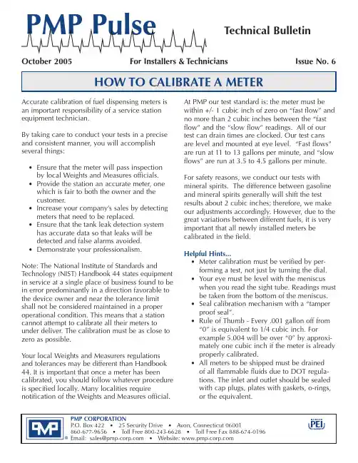
®The following procedure is suggested by our staff for conducting field meter tests. We have found it tobe an accurate and fast method for testing and calibrating meters.Step 1:(New or remanufactured meters) Slowly dispense several gallons of fuel through the meter before attaching it to the computer or pulser.The purpose of this step is to prevent damage to the computer or pulser. The meter will spin rapidly as the air in the lines is displaced by fluid. Run several 5 gallon drafts through the meter to completely purge it of air. Use the air bleed plug found on certain meters (older A.O. Smith, Gilbarco, and Southwest) to allow the air to escape. All air must be purged from the meter to obtain consistent results. (If the nozzle will reach the tank fill pipe, run 50 to 100 gallons through the meter.) This ensures that all meter parts are “broken in” and all air is purged. Meter parts will “take a set” if left in storage for a long time andmust be broken in again.Step 2:“Wet the can”by filling your test measure with fuel. Dump the fluid back into the tank until it stops flowing and starts to drip. Continue to drain, while counting to 10 seconds. This procedure leaves a very thin film of fluid on the inside of the can. By using a “wet can” and allowing a 10 second drain after each 5-gallon draft, you will be able to test the meter very accurately. The key is to consistently drain the test can the same way. Otherwise, the variation in thickness of the film of fluid will cause your results to vary by several cubic inches.Step 3:Run your first test after resetting the computer or electronic readout to zero. Fill the test measure at “fast flow”. The nozzle clip is on the highest flow notch. If the nozzle has no clip, hold it wide open. Observe whether there was a “computer jump” when the pump was activated. If there was a jump, your results will be invalid. Fill the can until you come to exactly 5 gallons on the computer or electronic readout.For electronic computers, each .001 of a gallon you run over or under 5,000 gallons represents .231 cubic inches of fluid. Hence, .004 gallons is approximately 1 cubic inch.For mechanical computers, it is essential to bring the gallon wheel back to the exact starting position. The width of the “0” line on the wheel is approximately equivalent to one cubic inch of fluid. One “trick of the trade” for mechanical computers is to set the price per gallon at $2.310 and observe the money readout. Since there are 231 cubic inches per gallon, 5 gallons would display $11.55 (5 x 2.31) on the money wheel. Each 1¢off from $11.55 is equivalent to 1 cubic inch in your test measure. If you failed to stop exactly at $11.55 (5.000 gallons), you will know how many cubic inches you ran over or under. Thereby, you will be able to make a more accurate meter adjustment and save time.Step 4:Observe the position of the fluid in the test can and adjust the meter in the direction that will bring it to the zero position. When reading the test can, it is important that you not introduce parallax into your observations. That is, your eyes should be level with the fluid level in the sight glass and the indicator line on the test can. The can must be level.Step 5:Run another 5-gallon “fast flow” test after draining the test measure and resetting the computer or readout. To obtain accurate results, it is important that the “fast flow” rate for the tests be as consistent as possible. Observe the results. Repeat Steps 3 - 5 until the meter is calibrated to the “zero” line within +/- 1 cubic inch.Step 6:Run a 5-gallon “slow flow” test after draining the test measure and resetting the computer or read-out. Set the nozzle clip to the lowest flow position. If the nozzle has no clip, test the device at 5 gallons per minute, or the minimum discharge rate marked on the device, whichever is less. Once again, this flow rate must be consistent for accurate results. Note: Most meters will over-deliver at very low flow rates.Step 7:Observe the test results.If the meter has been in service 30 days or less, National Institute of Standards and Technology (NIST) Handbook 44 allows a tolerance of +/- 3 cubic inches from “0” for both the fast and slow tests. If the unit has been in service longer than that, the allowable tolerance is doubled to +/-6 cubic inches. Metric tolerances are+/-50 milliliters from “0” in a 20 liter test for new or replaced meters and +/- 100 milliliters for older units.Bennett - 4000•To increase, move pin and turn lower dial counter-clockwise until the pin drops into an aligned hole. There is a tab on the lower dial to facilitate turning.•To decrease, move pin and turn lower dial clockwise.•Three holes equal approximately one cubic inch in a 5-gallon test measure.Bennett - SB-100Calibration - direction is marked on meter body•To increase, remove pin, turn calibration dial counter-clockwise, and replace pin.•To decrease, remove pin, turn calibration dial clockwise, and replace pin. •One hole equals approximately one cubic inch in a 5-gallon test measure.Use of the pin retainer on the opposite side of the dial allows adjustment by approximately one-half cubic inch.Gilbarco - Advantage, Highline, TrimlineCalibration - direction is marked on meter body.•To increase, remove pin, turn dial in counter-clockwise direction, and replace pin.Always complete the adjustment by turning the calibration mechanism ina clockwise direction.First turn it in a counter-clockwise direction past the point where youwant it and then back again.This takes out the clearance between the screw thread.•To decrease, remove pin, turn dial in clockwise direction, and replace pin.•One hole equals approximately one cubic inch in a 5-gallon test measure.Use of the bottom pin retainer allows adjustment by approximatelyone-half cubic inch.Gilbarco - Encore, Eclipse C+Calibration is performed electronically. There is no manual calibration adjustment mechanism on the meter. Refer to the dispenser operation manual for calibration instructions.LC / Liquid Controls - M5 (used in many high flow dispensers)•Loosen the screw on the collar that holds the adjuster thimble in place.•To increase, turn adjuster thimble to the left (unscrew).•To decrease, turn adjuster thimble to the right (screw in).The numbers shown horizontally on the thimble represent tenths of onepercent (0.001) of adjustment.This is equivalent to approximately one cubic inch in a 5-gallon test measure, or 23 cubic inches in a 100-gallon test measure.The smaller graduations between the numbers represent (0.0002) of adjustment.Each small graduation is equivalent to approximately 1/5th of one cubic inch in a 5-gallon test measure, or 41⁄2cubic inches in a 100-gallon test measure.The numbers shown on the upper portion of the adjuster (0 through 5)represent one percent of adjustment.Tighten the screw on the collar that holds the adjuster thimble securely.Schlumberger Centurion - SM100A / Tokheim 100•To increase, turn BOTH adjusting screws counter-clockwise.•To decrease, turn BOTH adjusting screws clockwise.Turning BOTH screws one “click” equals approximately one cubic inchin a 5-gallon test measure.NOTE: BOTH SCREWS MUST BE TURNED THE SAME NUMBER OF “CLICKS”. Southwest/Schlumberger - E-400•To increase, move pin clockwise and turn upper dial counter-clockwise until pin drops into an aligned hole.•To decrease, move pin counter-clockwise and turn upper dial clockwise until pin drops into an aligned hole.•Four holes equal approximately one cubic inch in a 5-gallon test measure. Tokheim•To increase, move pin and turn upper dial clockwise.•To decrease, move pin and turn upper dial counter-clockwise•Five holes equal approximately one cubic inch in a 5-gallon test measure.(continued)Universel Epsco / A.O. Smith•To increase, move pin and turn upper dial clockwise•To decrease, move pin and turn upper dial counter-clockwise•One hole equals approximately one cubic inch in a 5-gallon test measure. Wayne - 2PM 4,5,6•To increase, lift and rotate the adjustment knob in clockwise direction.•To decrease, lift and rotate the adjustment knob in counter-clockwise direction.•One notch equals approximately one cubic inch in a 5-gallon test measure. Wayne iMeterCalibration is performed electronically. There is no manual calibration adjustment mechanism on the meter. Refer to the dispenser operation manual for calibration instructions.Meter Calibration GuideAll manufacturers’numbers, names, trade names, trademarks and descriptions used here are for reference purpose only. None of the rebuilt items listed here are the products of the identified manufacturers.®PMP CORPORATIONP .O. Box 422 • 25 Security Drive • Avon, Connecticut 06001860-677-9656 • Toll Free 800-243-6628 • Toll Free Fax 888-674-0196Email:******************•Website:Form 116-1005Printed on recycled paper©2005 PMP CORPORATIONNotes。
油气测试仪安全操作及保养规程油气测试仪是用于测量油气的温度、压力和流量等性能指标的仪器设备。
它在石油、化工、航空、军工等领域具有广泛的应用。
在使用油气测试仪的过程中,合理的操作和保养不仅能够延长使用寿命,还可以保证设备的稳定性和安全性。
本文将介绍油气测试仪的安全操作及保养规程。
安全操作规程1. 设备检查在使用油气测试仪之前,必须对设备进行检查,以确保设备状态正常、安全。
具体操作如下:•检查设备的电缆、管路和连接部分是否紧固牢固。
•检查设备的外观和内部连通管道是否完好无损,是否有漏气、漏油、漏液现象。
•检查压力表或流量仪表的读数是否正常,是否需要校准。
2. 技能要求使用油气测试仪需要具备一定的专业技能和经验,以下是相关技能要求:•必须具备相关技能的专业人员操作;未经过专业培训的人员不得随意操作设备。
•操作人员必须具备相关知识,了解设备的工作原理和优化原理,熟练掌握相关技术参数,能够判断仪器数据的准确性和合理性。
3. 操作要求在使用油气测试仪进行测量时,应严格按照以下操作规程进行操作:•在进行操作前必须熟练掌握说明书,并按规程操作。
•在从系统中取样时,必须使用正确的取样管和阀门,避免样品污染。
•在接口处要注意舒适连接,以保证测量的精度和准确性。
•启动设备前必须先静态检查,在充分了解设备状态并确保处于正常工作状态后,方可进行启动操作。
•在操作过程中,要注意记录数据。
记录必须按要求进行,包括记录测量数据、必要的信息和备注。
4. 安全要求在油气测试仪使用过程中,必须严格遵守安全要求:•操作人员必须穿戴工作服、工作鞋或靴子、安全帽等安全防护装备,规定操作时必须戴防护手套、护目镜、口罩、头盔等特定安全防护用品,以保障人身的安全。
•操作人员对化学液体、瓦斯、氢气等特种气体必须先了解其危害性以及预防措施。
•对于燃气管道等易燃易爆区域内操作,必须有两人以上在场,必要时可以设置警戒标志或者警戒区域。
•在进行设备操作时,要避免产生火花和静电,避免产生爆炸等安全事故。
智能油井计量仪用户手册四川省科学城久利电子有限责任公司重要提示仪器利用前请仔细阅读本用户手册, 以便充分了解仪器性能,正确利用仪器。
用户欲了解产品规格及技术指标的其它情况,请直接与本公司市场部联系。
本用户手册内容会有更新,欲了解最新版本请与本公司市场部联系。
本用户手册发布日期:2013年12月目录1 ........................................................................................适用范围- 4 -2..........................................................................................工作原理- 4 -3.................................................................. 产品型号及表示方式- 4 -4 仪器介绍.................................................................. -5 -简介................................ - 5 -仪器的量程.......................... - 6 -5.技术性能.................................................................. - 6 -智能油井计量仪技术性能 .............. - 6 -仪器正常工作的必要条件 .............. - 8 -5.2.1流量范围......................... - 8 -5.2.2结蜡和利用寿命................... - 8 -5.2.3气、液比......................... - 8 -6.智能油井计量仪利用方式 ......................................... - 8 -井口固定装置 ........................ - 9 -6.1.1简介............................. - 9 -6.1.2接线方式......................... - 9 -井口数据录取器 ...................... - 9 -6.2.1井口数据录取器简介.............. - 10 -6.2.2井口数据录取器利用方式.......... - 10 -7.井口数据读取器..................................................... - 14 -井口数据读取器简介 ................. - 14 -井口数据读取器现场收集数据操作步骤.. - 15 -井口数据读取器回放操作步骤:(与计算机连接)- 16 -8 软件利用指南 ........................................................ - 16 -概述............................... - 16 -安装............................... - 17 -软件运行的初始设置 ................. - 17 -井口数据录取简易操作(笔记本方式).. - 18 -数据处置软件的利用 ................. - 19 -8.5.1 回放数据..................... - 19 -8.5.2 打开数据....................... - 20 -8.5.3数据处置窗口.................... - 21 -8.5.4 数据分析软件的利用 ............. - 26 -8.5.5常规设置和功能................. - 27 -8.5.6软件利用常见错误及处置方式:.... - 30 -9 配置清单................................................................ - 32 -10安装要求 .............................................................. - 33 -11联系方式 .............................................................. - 36 -1适用范围本说明书适用的范围是智能油井计量仪系列产品。
第1篇一、前言为确保输油站计量设备的正常运行,提高计量数据的准确性和可靠性,保障油品输送的安全生产,特制定本操作规程。
本规程适用于输油站内所有计量设备的操作和管理。
二、计量设备操作前的准备工作1. 操作人员应熟悉本规程,了解计量设备的性能、操作方法及注意事项。
2. 操作人员需通过专业培训,取得相应的操作资格证书。
3. 操作前,应对计量设备进行检查,确保设备完好、功能正常。
4. 检查设备电源、仪表、传感器、通讯接口等是否正常。
5. 检查设备清洁度,确保无污垢、油渍等杂质。
6. 检查设备运行参数,如温度、压力、流量等,确保在正常范围内。
三、计量设备操作流程1. 启动设备(1)打开设备电源,检查设备运行状态。
(2)启动设备,观察仪表显示,确认设备正常运行。
2. 设备校准(1)根据设备类型,选择合适的校准方法。
(2)按照校准步骤,对设备进行校准。
(3)校准完成后,记录校准数据,并存档。
3. 计量操作(1)根据输送油品类型,选择合适的计量器具。
(2)将计量器具与设备连接,确保连接牢固。
(3)启动输送设备,开始计量操作。
(4)观察仪表显示,确保计量数据准确。
4. 数据记录与处理(1)记录计量数据,包括时间、油品类型、流量、温度、压力等。
(2)对数据进行整理、分析,确保数据准确可靠。
(3)对异常数据进行调查、分析,找出原因,采取措施。
5. 设备停机(1)停止输送设备,关闭计量器具。
(2)关闭设备电源,确保设备安全。
四、计量设备操作注意事项1. 操作人员应严格遵守操作规程,确保设备安全运行。
2. 操作过程中,注意观察设备运行状态,发现异常情况立即停机检查。
3. 严禁操作人员擅自拆卸、改装设备。
4. 操作人员应定期对设备进行维护保养,确保设备性能良好。
5. 计量数据应准确、可靠,如有疑问,应及时上报相关部门。
6. 操作人员应掌握设备操作技能,提高操作水平。
五、计量设备操作人员职责1. 负责设备的日常操作、维护保养。

一.用途WS1.0×4.5-9.8型三相测试分离器橇块是针对油气井测试而设计的油气处理设备。
此设备是可实现油、气、水三相分离,同时集天然气、原油、污水计量、自动排水排油、安全泄放为一体的油气处理装置。
该装置设计技术先进、可靠、实用,而且工作效率高,运行平稳,占地面积小,操作十分方便。
本橇块适用于油、气、水三相分离的单井测试和计量。
二.主要技术参数1.设计压力:P=9.8MPa2.最高工作压力:P W=9.2MPa3.安全阀最低开启压力P d=9.2Mpa4.设计温度:80°C5.工作温度:0-50°C6.介质:油、水、天然气(含H2S体积比不大于7%)7.处理量:液体处理量:300m3/d,天然气:50×104 Nm3/d8. 气相分离精度:10μm9.外形尺寸:6750×2250×280010.设备总重:14500Kg三.结构及工作原理1.结构:WS1.0×4.5-9.8测试分离装置是以油、气、水三相分离器为主体的整体橇装式分离、处理、计量装置。
分离器由壳体、封头、进料组件、出气组件、人孔、液位控制组件、分离聚集组件、除沫器、油池、水池、鞍座等组成。
壳体是由钢板卷焊而成,壳体左上部设有进料组件,进料组件后部装有分离聚集组件。
壳体一端封头上设有DN400的人孔,可通过它进入分离器进行检验和维护。
在壳体上设有液位计、油位变送器、水位变送器接口,分别装有液位计、油位变送器、水位变送器。
装在筒体上部的安全阀可起超压保护作用。
分离器上还设置有压力表、温度计以及排污、排水、排油接口。
与分离器相连的管线分别为:(1)原料输入管线,此管线由无缝钢管及原料输入总控制球阀、旁通组成;(2)输气管线:由无缝钢管及阀件组成。
管线上装有一体化孔板流量计、球阀、基地式调压阀、止回阀、压力表装置等。
(3)仪表、阀件供气管线:此管线主要由无缝钢管和球阀、调压阀、缓冲罐、压力表装置等组成。
长安跨越王油气两用的说明书以下是长安跨越王油气两用安装的说明书:1.安全性:要确保长安跨越王油气两用的安全运行,必须出合格的专业人员按此说明书进行正确的安装及调试要特别注意相关的安全规定(如DIN-VDE DIN-DVGW)火焰监测装置、限制装置,调节机构以及其它安全装置只能由制造,或其委托单位进行安装。
不遵守规定可能导致人员伤亡及重大物质损失等严重后果。
2.人员资格:本说明书所指的合格人员为熟悉安装调试并有足够能力从事其工作的人员,如:受过培训,并有能力根据安全技术的标准操作。
接地及标识电器的> 受过培训,并有能力在现场对燃气装置进行安装、调试及维修的。
3.操作说明:每台长安跨越王油气两用所附的操作说明必须放置在设备周围显眼处。
在操作说明上必须标明最近的服务商联系地址。
4.指导:故障经常是由于误操作引起的。
因此司职人员应被详细告知长安跨越王油气两用的相关常识。
如经常出现某一故障,则应通知服务商。
5.安装:安装长安跨越王油气两用必须按相应的标准及规定进行。
因此安装者必须确保所有的规定得到贯彻执行。
应当认真对待安装、调试及保养等各项工作。
燃油要符合 DIN51603的标准。
电气接线图每台长安跨越王油气两用都附有一详细的接线图。
6.保养:如在保养及检验工作中密封件被打开,在重新安装时必须清洁密封面并注意保持密闭性能。
维护与保养根据DIN4755 及DIN4756的规定,全套设备应至少一年进行一次维护与保养。
根据实际情况还应对相应部件的气密性进行复查。
燃烧后的烟气值在每次保养及故障处理时要进行测量。
称重式油井计量撬使用说明沈阳工业大学通益科技有限公司目 录一、用途及特点.............................................................................- 2 -二、基本原理..................................................................................- 2 -2.1、称重式气液两相计量器的组成原理....................- 3 -2.2多通阀组成原理......................................- 4 -2.3计量撬的组成原理.....................................- 5 -三、计量撬执行标准和规范.........................................................- 5 -3.1 机械部分:..........................................- 5 -3.2 零件结构要素标准:.................................- 6 -3.3 材料标准:..........................................- 6 -3.4 电气部分:..........................................- 6 -3.5 其它标准:..........................................- 7 -四、计量撬的控制系统.................................................................- 7 -4.1本地控制............................................- 7 -4.2远程控制............................................- 9 -五、基本技术指标.......................................................................- 12 -六、使用注意事项.......................................................................- 13 -七、关于计量器标定设备及方法...............................................- 13 -7.1设备................................................- 13 -7.2方法................................................- 14 -八、常见硬件故障及可能原因...................................................- 14 -九、技术支持与服务...................................................................- 15 -附录:设备图纸...........................................................................- 16 -一、用途及特点针对原油含气不易排出,人工计量难度大、费时费力的现状,设计了一种集分离与计量功能于一身的“称重式油井计量撬”,该计量器能消除由于油中含气造成的假体积而带来的测量误差,采用称重的方式对流经计量器的原油进行称重,通过累计一定时间内流过计量器中的原油重量,计算出油井的产液量。
石油分析仪器使用说明书使用说明书1. 石油分析仪器概述石油分析仪器是一种用于测试和分析原油、石油产品以及相关样品的专用设备。
本使用说明书旨在详细介绍石油分析仪器的操作步骤和注意事项,以确保用户能够正确、安全地使用该仪器。
2. 安全操作指南2.1 仪器操作前的准备在操作仪器之前,确保所处环境稳定、整洁,并检查仪器是否完好。
如遇到异常情况或仪器故障,请联系专业维修人员进行维护。
2.2 个人防护措施在操作仪器时,建议佩戴合适的个人防护设备,如手套、护目镜等。
同时,注意避免直接接触样品,避免产生有害物质飞溅。
2.3 电源及电气安全仪器应连接至稳定的电源,并请勿触摸电器部件,以免发生触电危险。
如发现电气故障或线缆破损,请立即停止使用并联系售后服务。
3. 仪器操作步骤3.1 样品准备将待测样品按照要求准备好,并确保样品不受污染。
若需要稀释或配制试剂,请按照标准程序进行。
3.2 仪器开机与校准连接仪器电源,并按照操作界面上的提示进行开机操作。
根据仪器要求,进行校准步骤,确保仪器的准确度和稳定性。
3.3 样品测试将样品放置在仪器的测试台上,并按照操作界面上的指示选择相应的测试方法。
启动测试程序后,等待仪器自动完成测试。
3.4 数据分析与记录仪器完成测试后,将自动显示测试结果,并可导出为数据文件。
根据需要,用户还可将结果打印或保存到电脑或其他存储设备上进行进一步分析和比较。
4. 维护与保养4.1 定期清洁根据使用频率,定期对仪器进行清洁,以保持其正常运行和延长使用寿命。
使用柔软的湿布和专用清洁剂擦拭外壳和测试台面。
切勿将清洗剂直接喷洒到仪器内部。
4.2 保养注意事项在使用过程中,应注意仪器的散热、防尘和防潮。
避免长时间进行连续测试,以免过度使用导致仪器损坏。
若发现仪器有异常噪音或异常操作,请及时联系售后服务。
4.3 维修与更换部件在需要维修或更换仪器部件时,务必由专业人员进行操作。
若需要更换零部件,请使用原厂配件,以确保仪器的正常运行。
史上最全油气水三相分离器操作规程油气水三相分离器是油气田勘探开发中,用来对井出液进行加热、分离和计量的重要装置。
由于此装置配备很多仪表、阀门和管线,因此操作起来有很多需要注意的事项,江苏鲁迪石化工程师告诉我们,为保证油气水三相分离器安全稳定运行,需遵守以下操作规程。
1.油气水三相分离器的安装要求水平稳固,与井口保持规定的距离。
放空火炬引至安全距离以外。
2.装置的进出口管线连接后,在投运以前,应进行气密性试验,试验过程按《使用手册》规定进行。
3.油气水三相分离器运行中,为保持装置适当的操作压力和天然气流量,可以适当的调整入口节流阀和天然气的出口阀开度,并记录调整时间和调整量。
4.在运行中,每天检查一次水套炉的水位,保证盘管完全浸没水中。
否则应补水。
5.装置运行中,每两个小时应巡查一次。
巡查项目有:各压力指示表数据,燃烧用气压力(0.4Mpa)是否正常,装置运行状态是否正常,并排放净化器底积水。
6.当装置试运或运行中,出现阀门、法兰或接头泄漏时,应立即切断进气,泄压后进行处理。
切不可带压紧固。
7.计算机测试系统中,参数输入的操作,未经授权,不得更改各项参数。
8.油气水三相分离器运行中,当压力发生上限报警时,要适当关小入口节流阀。
9.装置运行过程中,天然气温要不低于25℃。
通常保持在30℃左右。
10.装置运行过程中,安全阀和爆破片前后的阀门务必保持全开状态。
11.装置运行状态下应将箱门和天窗打开并固定,防止箱体内的可燃气体浓度过高。
12.每天进行一次计算机声音报警试验(临时改变报警参数)。
13.计算机检测过程中,不允许进行其它软件操作,否则可能造成存储数据错误。
14.装置的开停车步骤按《使用手册》中给出的程序进行。
15.在寒冷季节,当装置停车可能出现冰冻时,应排出装置各部分的积液。
各玻璃管液位计从排污阀放出积液,然后关闭液位计的上下入口阀和排污阀。
水套炉中的高压盘管的积液采用气体吹扫方法清除。
具体方法是,在关闭井口阀门后,至少3个小时以上,使井筒中的液体沉降,然后再打开井口阀门,尽量降低分离器的压力,吹扫10—20分钟。
IC 燃气表说明书概述IC 燃气表是一种用于测量和记录燃气消耗量的设备。
它具有精确测量能力和安全性能,广泛应用于家庭、商业和工业等领域。
本说明书将为您提供有关 IC 燃气表的详细信息和操作指南。
产品特点•高精度测量:IC 燃气表采用先进的测量技术,能够精确测量燃气消耗量,保证数据的准确性。
•数据记录功能:IC 燃气表具备数据记录功能,可以记录并存储历史燃气消耗数据,方便用户进行数据分析和管理。
•安全可靠:IC 燃气表采用安全可靠的设计和材料,确保使用过程中的安全性和稳定性。
•易于安装和操作:IC 燃气表具有简单的安装和操作过程,用户可以轻松完成安装和日常使用。
技术规格技术指标参数测量精度±1%工作温度范围-20°C ~ 50°C工作湿度范围5% ~ 95%接口类型RS485防尘防水等级IP65应用领域IC 燃气表广泛应用于以下领域:1.家庭使用:用于记录家庭燃气消耗量,帮助用户进行计费和节能。
2.商业使用:用于商业建筑、餐饮等场所的燃气计量与管理。
3.工业使用:用于工业生产和能源管理等领域,提供精确的燃气消耗数据供企业参考。
安装与操作安装步骤1.将 IC 燃气表与燃气管道连接,确保连接口密封性良好。
2.检查燃气表的安装环境,确保无火源和易燃物质。
3.将电源线连接到适配器并插入供电插座。
操作指南1.上电:连接适配器并插入供电插座,燃气表将自动开机。
2.参数设置:根据需要,可以通过IC燃气表的菜单界面进行相关参数的设置,如日期时间、费率等。
3.数据查询:通过IC燃气表菜单界面可以查询历史燃气消耗量和其他相关数据。
也可以通过RS485接口连接外部设备进行数据查询和管理。
注意事项1.请确保安装 IC 燃气表的环境无火源和易燃物质,确保使用过程中的安全性。
2.请勿随意拆卸或更换 IC 燃气表的零部件,以免影响正常工作。
3.请按照操作指南正确操作 IC 燃气表,确保数据的准确性和操作的稳定性。
OTS60PB, 60AF/2, 80AF/2, 100AF/2, VCM100 Automatic Oil Test SetsDESCRIPTIONThe Megger range of automatic oil testers offer fully automatic testing with many advanced features. The design allows the operator to simply prepare an oil test vessel, load it with the sample oil, place it in the chamber and initiate the test sequence. The test set then carries out, the series of tests as specified in a large number of oil testing specifications. These define the sequence of tests including the stand and stir times, rate of voltage rise and number of tests resulting in a calculation of the average value of the oil breakdown strength. Withstand or proof testing can also be selected. This test subjects the oil to a preselected voltage for 1 minute to check for a breakdown.The OTS60PB is a fully automatic, battery powered, portable oil test set. The test voltage is electronically controlled to the maximum of 60 kV.Designed for on site testing, the instrument is supplied in a rugged carrying case with a handle for ease of transportation. An internal rechargeable battery gives a large number of tests before recharging. A clear display shows a menu of test options and guides the operator through the set up programme, illustrates the correct test electrodes and gap to use, shows the progress of each test and gives the results of the test sequence. The result can be set to give either a numerical average (with standard deviation where specified) or a pass/fail message. The display can be set to read in English, French, German, Italian, Spanish and Portuguese. An optional printer kit enables hard copies of results to be produced. Accessories, such as the battery charger,spare vessels, spare electrodes and a spacing gauge are located in an attached compartment. Stirring is carried out by a motor driven paddle stirrer.The OTSAF/2 range are laboratory instruments with many advanced features. Three versions are available with maximum test voltages of 60 kV,80 kV and 100 kV.They offer fully automatic operation plus the benefit of a builtin printer to produce a hard copy of the test results andthe ability to program up to five user defined tests for individual applications. The withstand test can be set to operate at any test voltage and with an initial stand time. The dot matrix liquid crystal display can also be set toread in one of six languages. An oil test vessel, configured to suit the IEC156 test specification, is supplied with the instrument.A large, backlit, liquid crystal display shows test menus,set up screens and results. The resolution of the high voltage output is displayed to 0,1 kV.Results can be printed on the internal dot matrix printer or transferred via the RS232 interface to an external printer or PC. Printouts are automatically time and date stamped. Standard stirring with the OTSAF/2 is achieved by a magnetic stirrer bar.Additional vessels are available optionally, including one suitable for testing to the ASTMD1816 specification. This calls for stirring to be carried out by a motor driven impeller. Each test can be selected with either magnetic stirring, propeller stirring or no stirring. The VCM100 is a calibration meter suitable for verifyingthe calibration of oil test sets. The meter will enable theI Microprocessor controlled fully automaticoil test setsI Wide choice of vessels and accessories I Portable and laboratory unitsOTS VCM100 Scale Plate(programmed in OTS60PB, OTS60AF/2, OTS80AF/2 and OTS100AF/2)Intermediate Number Maximum Duration of SelectedStand Time Of T ests test sequenceOTS60BOTS60PB OTS60AF/2, OTS80AF/2 AND OTS100AF/2Electrode Shape B12,7 mm (0,5 in) Spherical Electrodes Electrode Shape CElectrode Shape D25,4 mm (1 in) Cylindrical Electrodeswith 0,5mm edge radiusPRINTER INFORMATIONThe OTS60PB Printer Kit includesa24 column impact printer withintegral rechargeable batteries anda mains adaptor which operatesfrom 85 V to 265 V a.c. (50/60 Hz).The printer is 105 mm x 195 mmx90 mm and weighs 625 g.UKArchcliffe Road Dover CT17 9EN EnglandT+44 (0) 1304 502101 F+44 (0) 1304 207342UNITED STATES4271 Bronze WayDallas TX 75237-1088 USAT800 723 2861 (USA only)T+1 214 333 3201F+1214 331 7399OTHER TECHNICAL SALES OFFICESNorristown USA, Toronto CANADA,Mumbai INDIA, Trappes FRANCE,Sydney AUSTRALIA, Madrid SPAINand the Kingdom of BAHRAIN.Registered to ISO 9001:2000 Cert. no. Q 09290Registered to ISO 14001-1996 Cert. no. EMS 61597OTS60PB_AUTO_DS_en_V17Megger is a registered trademark。