
LS-PrePost教程 (CHN)
- 格式:ppt
- 大小:8.24 MB
- 文档页数:257


Mesh Overviewz ShapeM-Simple shell/solid meshing interfacez AutoMesh-Surface mesh interface.z SolidMesh-Solid mesh interface.z BlockM-3D block mesher interface.z NlMesh-2, 3, and 4 line mesh interface.z TetMesh-Tetrahedron mesher interface.z BMesh-Blank mesher interface.z ElemGen-Create beam, shell, and solid elements.z NodeEdit-Show, create, delete, and modify nodes.z ElemEdit-Show, create, delete, and modify elements.z MassTrim-Mass trim interface.z Spot Weld-Generate spotweld elements from a spotweld file.z SphGen-Sph particle generation interface.ShapeMPurpose:This interface, often used for generating solid meshes for ALE simulations, can be used to generate solid and shell meshes. Function:Box_Solid : Define a box and generate solid mesh of it.Box_Shell : Define a box and generate shell mesh of it.4N_Shell : Define four node surface and generate shell mesh of it.Sphere_Solid : Define a sphere and generate solid mesh of it.Sphere_Shell : Define a sphere and generate shell mesh of it.Cylinder_Solid : Define a cylinder and generate solid mesh of it.Cylinder_Shell : Define a cylinder and generate shell mesh of it.Circle_Shell : Define a circle and generate shell mesh of it.Sample:no sample.Box_Solid/Box_Shellz Region : Use General Selection Interface to get region max and min values.z Define_Box : Use Entity Operation Interface to get box max and min values.z PMin/PMax : Use Position Dialog to get minimum/maximum point.z X/Y/Z : Enter x/y/z-coordinates of minimum and maximum point.z Number : Enter number of elements along x/y/z.z Size : Enter size along x/y/z.z Vx/Vy/Vz : Enter Number/Size along x/y/z.z Gap : Extend min/max of box by this value.z Target Name : Enter target part name.z Target Part ID : Enter target part ID.z Start Element ID : Enter starting element ID.z Start Node ID : Enter starting node ID.z Create : Create mesh for the entity.z Reject : Reject the created mesh.4N_ShellSphere_Solid/Sphere_Shell z Accept : Accept the created mesh.z Done : Exit meshing interface.z Checkbox P1/P2/P3/P4 :Use General Selection Dialog to Pick node for point 1/2/3/4. z Button P1/P2/P3/P4 :Use Position Dialog to get point 1/2/3/4.z Text P1/P2/P3/P4 :Enter coordinates in format "x, y, z" for point 1/2/3/4.z NxNo. :Enter number of elements along x.z NyNo. :Enter number of elements along y.z Radius : Enter radius of sphere.z Density : Enter density of sphere.z Center[Position] : Use Position Dialog to get sphere center. z x/y/z : Enter x, y, z of the sphere center.z Direct1 : Call Direction Dialog to get direction 1.z Direct2 : Call Direction Dialog to get direction 2.z dx/dy/dz : Set direction x/y/z for 1/-1 (toggles).Cylinder_Solid/Cylinder_ShellCircle_Shell z Radius : Enter cylinder radius.z Length : Enter cylinder length.z Num Ele : Enter number of elements in circumferential direction. z Num : Enter number of elements along the length of the cylinder. z Position : Call Position Dialog to get position.z Direction : Call Direction Dialog to get direction.z dirx/diry/dirz : Set direction x/y/z for 1/-1 (toggles).z Top And Bottom : Create Top and Bottom Circle Shell.z Radius : Radius of circle.z Density : Density of Circle (Must more than 2).z Radius_In : Radius of circle inside.z Density_In : Density of Circle Inside (Must more than 2)z Angle : Span Angle.z Center[Position]xyz : Call Position Dialog to get position.z Direct1 : Call Direction Dialog to get direction 1.z Direct2 : Call Direction Dialog to get direction 2.z dx/dy/dz : Set direction x/y/z for 1/-1 (toggles).AutoMeshPurpose:This interface is for surface mesh generation. Two meshing methods are available: By size and By Deviation.Function:Auto Mesh : Size mode creates uniformly sized elementsTool Mesh : Specifically for metalforming applications where surfaces may contain very small radii that need to be meshed accurately, and at the same time have flat areas that require a relatively coarse mesh. Tool meshing requirements are very different from those of structural finite element analysis.Sample:Two kind mesh comparison : show the difference between size-based and deviation-based.Automesh:z Size : Select the size mode.z Deviation : Select the deviation mode.z Mesh Type : Generate triangle mesh only or mixed.z Elem Size : Enter average element size.z Compute : Compute mesh parameter by model extend.z Reset : Reset mesh parameter to default.z Show Meshed Boundaries : Before Accept and After Mesh, will become sensitive. Show the boundary node as blank square.z Auto remesh boundary : Before Accept and After Mesh, will become sensitive. On the boundary, left click to increase the nodenum and right click to decrease it. Then automesh it according to the new boundary.z Manual remesh boundary : Before Accept and After Mesh, will become sensitive. On the boundary, left click to add a newnode and right click to remove a node. Then automesh it according to the new boundary.z Mesh By GPart : The mesh generated from same GPart will be organized into same part.z Ignored Hole Size : Holes under specified size will be ignored.z Part ID : Assign new generated mesh to this part or create a new part if this part id doesn't exist.z Mesh : Generate shell mesh for selected surfaces.z Reject : Reject the last operation.z Accept : Accept the last operation.z Done : Exit this dialog.Toolmesh :Two kind mesh comparisonSolidMeshPurpose:Generate solid mesh of mappable volumes.Function:Suppress : Suppress geometry edges which resist sweeping. Meshing : Generate solid mesh manually or automatically..Sample:no sample.Suppress:z Max Elem Size : Enter maximum element size.z Min Elem Size : Enter minimum element size.z Max Deviation : Enter maximum deviation ratio.zMax Angle: Enter maximum feature angle.size-based mesh deviation-based mesh Suppress Edge pick geometry edge to be suppressed on graphic area.MeshingBlockMeshPurpose:This interface is for index based mesh generation and is similar to mesh generation methods used in LS-INGRID. This capability is under development and eventually will be expanded to be a very powerful addition to LS-PrePost.Function:Create : Create blocks.Parameter : Parameter and Expression.Bland/Del : Blank or delete blocks.Rd/Write : Read and write command files.Move Pts . : Move points.Distribute : Distribute blocks' nodes.Rotate Pts : Rotate points.Project: Project points/lines/surfaces of blocks to geoemtry.Try Meshing Automatically : Once the decomposition is done, click this button try to mesh automatically. all the volumes have to be mappable, otherwise unmappable volume will be omitted.Volume by Closed Faces : Pick volume to be sweep on graphic area. For manual purpose only.Target Surface : Pick face as sweep target on graphic area. For manual purpose only.Hint : Click until found the proper target face.Mesh on Sources(Optional) : Pick sources' mesh if needed. For manual purpose only.Elem Size : Specify the element size.Default Size : Click to get the reference element size.Layer : Check to enable layer control. For manual purpose only.Bias : Check to enable bias control. For manual purpose only.Intensity : Specify the bias intensity. For manual purpose only.Mesh : Generate solid mesh.For manual purpose only.Reject : Reject the last sweep.Accept : Accept all sweep.Done : Exit the interface and accept all sweep.Info : Show internal node coordinate of given block.Sample:no sample.Create:Multiple Blocks : Create multi blocks.Single Block : Create single blocks.Butterfly Block : Create a butterfly block.z Create : Create blocks.z Parameter : Parameter and Expression.z Bland/Del : Blank or delete blocks.z Rd/Write : Read and write command files.z Move Pts. : Move points.z Distribute : Distribute blocks' nodes.z Rotate Pts : Rotate points.z Project : Project points/lines/surfaces of blocks to geoemtry.z Info : TODOz Type : Select block type.z I Index List : I index list for blocks.z J Index List : J index list for blocks.z K Index List : K index list for blocks.z X Position List : X coordinate for blocks.z Y Position List : Y coordinate for blocks.z Z Position List : Z coordinate for blocks.z Part ID : The generated mesh will belong to.z Create : Create the block.z Reject : Reject the last operation.z Accept : Accept the last operation.z Done : Exit interface.z P1 : When checkbox is checked, pick from graphic. Click button P1 to call Position dialog to create a Point. Or Enter x/y/z.z Px : Same as P1z No. of Elements(I J K) : Enter number of elements along I, J, K.z Density : Density of the cylinder perimeter.z Radius : Radius of the cylinder.z Length : Length of the cylinder.z R : Number of elements in Radius direction.Blank/Del : Rd/Write:Move Pts:z L : Number of elements in Length direction. z Is Quartered :z Is Tubal : The cylinder is empty.z Inner R: Sensitive when Is Tubal is checked. The inner raidus of cylinder.z Parameter or Expression : Enter parameter or expression. Such as A=150 or R=T1*sin(T2). z Create : Create a parameter or expression.z Delete : Delete a parameter or expression.z Coordinate X : Function to evaluate x coordinate.z Coordinate Y : Function to evaluate y coordinate.z Coordinate Z : Function to evaluate z coordinate.z Apply : Apply eval function to current domain block.z Undo : Undo the last operation.z Redo: Redo the last Undoed operation.z I Index List : I coordinate of blocks to be blank or delete.z J Index List : J coordinate of blocks to be blank or delete.z K Index List : K coordinate of blocks to be blank or delete.z(Un)Blank : Blank blocks.z Reverse Blank : Reverse blank status of blocks.z Display All : Display all blocks.z Delete : Delete blocks.z Undelete: Undelete blocks.z Empty : Empty current buffer for blockm commmand.z Read : Read command file.z Write : Write command file.z NULL : No constraint.z X Aixs : Constraint to X Axis.Distribute:Rotate Pts: Project Point : Project to point.Line : Project to line. Surface : Project to surface.Shell Element : Project to shell elements. Plane : Define a plane with a origin and a vector. Cylinder : Define a Cylinder with a origin, a vector and a radius. Sphere: Define a Sphere with a origin and a radius.z Y Aixs : Constraint to Y Axis.z Z Aixs : Constraint to Z Axis.z Screen X Axis : Constraint to screen X Axis.z Screen Y Axis : Constraint to screen Y Axis.z XY Plane : Constarint to XY Plane.z XZ Plane : Constarint to XZ Plane.z YZ Plane : Constarint to YZ Plane.z Screen Plane : Constraint to screen plane.zDistance: Sensitive according to former option. the distance on x/y/z direction.z Along a whole line : Distribute edge along a whole line.z Edge along line : Distribute edge along line.z Vectex Interpolation : Vectex Interpolation in Bi-linear and Tri-linear Multiple Faces and Solids Interpolation.z Edge Interpolation : Edge Interpolation in Bi-linear and Tri-linear Multiple Faces and Solids Interpolation.z Linear : Apply Linear Interpolation.z Zoning Ratio : Zoning Ratio (a positive number).z Both Ends : Relative spacing of nodes of an edge from both ends.z Zoning : Apply Edge Zoning.z Undo : Undo last interpolation.zRedo: Redo last interpolation.z NULL : No constraint.z X Aixs : Constraint to X Axis.z Y Aixs : Constraint to Y Axis.z Z Aixs : Constraint to Z Axis.z Screen X Axis : Constraint to screen X Axis.z Screen Y Axis : Constraint to screen Y Axis.zScreen Z Axis : Constraint to screen Z Axis.zPoint : Project to point.Infoz Line : Project to line.z Surface : Project to surface. z Shell Element : Project to shell elements. z Plane : Project to a plane.z Cylinder : Project to cylinder. z Sphere : Project to sphere. z Pick Point : Get XYZ at pick location on curve.z Nearest Point : Get XYZ at nearest point on curve.z End Point : Get XYZ at end of curve.z Mid Point : Get XYZ at middle of curve.z X : Project in X Component.z Y : Project in Y Component.z Z : Project in Z Component.z Only Face Inner Nodes : Project the Inner nodes when projecting Face(s).z Blank Blocks : Blank or unblank Blocks.z Project : Project the Block.z Undo : Undo last Projection.z Redo : Redo last Projection.z Closest 3D proj dir . : Project Block to mesh in closet 3D direction.z Vector projection : Project Block in specified vector direction.z Position : Select a Coordinate as the Orginal Point.z Direction : Select a Direction as Plane Normal.z Radius : Enter the radius for cylinder.z Position : Select a Coordinate as the Orginal Point.z Direction : Select a Direction as Plane Normal.z Closest 3D proj dir . : Project Block to mesh in closet 3D direction.z Vector projection : Project Block in specified vector direction.z Radius : Enter the radius for sphere. z Position : Select a Coordinate as the Orginal Point.z Closest 3D proj dir . : Project Block to mesh in closet 3D direction.z Vector projection : Project Block in specified vector direction.NLine MeshPurpose:This interface is for shell mesh generation using curves and often useful in cases where a topology mesher leaves holes due to missing CAD surface data.Function:2 Line Shell : Create a mesh between 2 lines 3 Line Shell : Mesh a region bounded by 3 lines 4 Line Shell : Mesh a region bounded by 4 lines Line Sweep : Create a mesh by sweeping one line along another lineSamples:no sample.2/3/4 Line Shellz I Index List : I Coordinate of one block.z J Index List : J Coordinate of one block.z K Index List : K Coordinate of one block.z I Index : I Coordinate of one Internal Node.z J Index : J Coordinate of one Internal Node.z K Index : K Coordinate of one Internal Node.z OK : Get the internal node coordinate.zCoordinate of Internal Node : Show internal node coordinate in the list.z Number of elements : Mesh by number of elements.z Element size : Mesh by element size.z Point of Line : Mesh by existing points of line.z N1 : Enter or adjust number of elements along line 1.z Ratio : Bias radio.z Two End : Bias from two end.z N2 : Enter or adjust number of elements along line 2.z N3 : Enter or adjust number of elements along line 3.z N4 : Enter or adjust number of elements along line 4.z Part Id : Enter or select target part ID.zNew PID : Get new default part ID.Line SweepTetraMeshPurpose:Use this interface to generate a solid mesh of tetrahedron elements.Function: Skin Remesh : Remesh a skin surface.Tetrahedral Mesh : Generate a tetrahedral mesh of a skin surface.Move : Move skin mesh or tetrahedral mesh to a new position.Sample:no sample.Dialog:z Mesh It : Perform meshing.z Accept : Accept the created mesh.z Reject : Reject the created mesh or the selected lines.z Done: Exit the nLMesh Interface.z N1: Enter or adjust number of elements along cross section.z Ratio : Bias ratio.z Two End : Bias from two end.z N2: Enter or adjust number of elements along sweep path.z Native Path Tangent : Use native curve tangent as sweep direction.z Center Align(move) : Generate the shell mesh with the sweep path center aligned.z Pick a skin Part : pick a part from graphic when entering this dialog.z Part List : Popup list of current parts for selection.Skin Remeshz Min edge size : Enter or change minimum element edge size for remesher.z Max edge size : Enter or change maximum element edge size for remesher.z Remesh : Remesh the skin surface.z Reject : Reject the remesh operation.z Save : Save skin or remesher skin as a new part.Tetrahedral Meshz TetMesh : Prepare selected part and send to tetrahedron mesher.z Reject : Reject tet mesh.z Accept : Accept tet mesh.z Create 10 node tetra : Create 10 node tetra elements instead of 4 node. Only take effect with "Accept".Movez X/Y/Z : Global X/Y/Z shift for new part from filled part. will affect the location of Skin also.z Move : Move temporary tetrahedron part in Global X, Y, or Z.z Clear : Clear picked part.z Done : Exit TetMesh Interface.BlankMeshPurpose:This interface is primarily intended for mesh generation of blanks for metalforming simulations, but it may also have applications in other areas. Function:4 Pnts : Using 4 Corner Nodes (of a blank) and Element Size to generate a mesh.Rect : Mesh rectangle of given Length and Width with element size or number of elements.Curve : Allows a mesh to be created on an enclosed curve. Element alignment can be along global axis or user defined. Mesh boundary options are as follows: Smoothed, Left Jagged (and optionally filled with trias), or No-Trim (creates a rectangular blank without trimming.Sample:no sample.4 Pntsz Pick : Pick node on model to define Node 1/2/3/4.z P1 : Call Position Dialog for Points 1.z P2 : Call Position Dialog for Points 2.z P3 : Call Position Dialog for Points 3.z P4 : Call Position Dialog for Points 4.z Elem Size : Element size for the blank.z Quality Statistic : Statistic quality of generated elements before accept.z Part ID : Part ID for the current blank.z New : Get a new part ID from the current model.z Start NID : The starting node id of of new created blank mesh.z Start EID : The starting element id of of new created blank mesh.z Create : Create the blank mesh.z Reject : Reject the last operation.Rect z Accept : Accept the last operation.z Done : Exit this dialog.z Location : the left bottom corner of this rectangle.z Position : Call Position Dialog for location4.z Update : Update the location.z U Offset : Enter or adjust plane center in the u direction.z V Offset : Enter or adjust plane center in the v direction.z Width : Enter or adjust width of blank.z Height : Enter or adjust height of blank.z X : Change plane normal to global x.z Y : Change plane normal to global y.z Z : Change plane normal to global z.z Normal : Call Direction Dialog to creat plane normal.z Update : Update plane normal.z Size : Give element size for blank.z Density : Give number of elements for blank.z Elem Size : Set or adjust element size for the blank (along diagonal). z U Density : Set or adjust number of elements along u direction.z V Density : Set or adjust number of elements along v direction.z Outline : Pick curve(s) to define the outline boundary.z Holes : Pick curve(s) to define holes.z By Surface: Define outline and holes by surfacez Smooth : Smooth the interior nodes after trimming (enter number of iterations).z Iterate Num :z Boundary Smooth : Smooth the nodes on the boundary after trimming.z Jagged Edge : Do a rought trim keeping the quadratic shape of the elements.z Tria Fill : Fill interior boundary notches with triangular elements.z No Trim : Create a quadratic mesh that covers the curves but performs no trim.z X : Set alignment direction along X.z Y : Set alignment direction along Y.z Z : Set alignment direction along Z.z Dir : Call Direction Dialog to create alignment for the elements.z Alpha : Rotate the above given alignment direction by this angle.z Size : Element size for the blank.ElemGenPurpose:This interface provides a variety of methods for generating beam, shell, and solid elements.Function:z Beam : Generate beam elements.{Edge : Create Beam by Edge.{Curve : Create Beam by Curve.{Node_Drag : Create Beam by Node_Drag.{Node_Spin : Create Beam by Node_Spin.{Shell_Diagonal : Create Beam by Shell_Diagonal.z Shell : Generate shell elements.{Solid_Surface, Solid_Face or Edge_Extend : Create shell by Solid_Surface, Solid_Face or Edge_Extend.{Edge_Drag : Create shell by Edge_Drag.{Edge_Spin : Create shell by Edge_Spin.{Segment_Set : Create shell by Segment_Set.{Fill_Holes : Create shell by Fill_Holes.z Solid : Generate solid elements.{Solid_Face_Drag, Solid_Face_Offset or Solid_Face_Spin : Create solid by Solid_Face_Drag, Solid_Face_Offset or Solid_Face_Spin.{Shell_Drag, Shell_Offset or Shell_Spin : Create solid by Shell_Drag, Shell_Offset or Shell_Spin.{Shell_Thickness : Create solid by Shell_Thickness.{Two_Shell_Sets : Create solid by Two_Shell_Sets.{Shell_Sweep : Create solid by Shell_Sweep.{Tetra_2_Ten or Hex_2_Tetra : Create solid by Tetra_2_Ten or Hex_2_Tetra.Sample:z Sample1 : Show how to create element Beam.z Sample2 : Show how to create element Shell.z Sample3 : Show how to create element Solid.Beamz Element ID : Enter new element starting ID.z New ID : Use default new element ID.z Part ID : Enter part ID for newly generated elements.z Pick PID : Pick part ID from graphics, part type must be consistent with the element type to be created.z New PID : Use default new part ID.z New node : Check to create new nodes.z Beam By : Set beam element generation method.z Create : Create element.z Reject : Reject last generated element.z Accept : Accept all new generated elements.z Done : Exit from element generate interface.z Third Node : Set third node on/off.z Direction : Get direction by Direction Dialog.z X : Set X direction.z Y : Set Y direction.z Z : Set Z direction.z Node ID : ID of the third node.z Curve. : Create beam just be curve without any change.z Size : Curve mesh by element size.z Num : Curve mesh by number of element.z Value : Enter size or number of elements (if zero segment by points).z Thickness : Set total thickness for generation.z Segment : Set number of segments for generation.z Direction : Get direction by Direction Interface .z X : Set direction 1,0,0 (click 2nd time to reverse).z Y : Set direction 0,1,0 (click 2nd time to reverse).z Z : Set direction 0,0,1 (click 2nd time to reverse).z Angle : Set total angle for generation.z Segment : Set number of segments for generation.z Position : Get position with Postion interface.z Sh Diagonal : Shell diagonal.Shellz Sh Diagonal13 : Shell diagonal 1,3.z Sh Diagonal24 : Shell diagonal 2,4.z Sh Diagonal Maxwrap : Shell diagonal by maxwrap.Create Shell by Edge_Drag:z Thickness : Set total thickness for generation.z Segment : Set number of segments for generation.z Direction : Get direction by Direction Interface.z X : Set direction 1,0,0 (click 2nd time to reverse).z Y : Set direction 0,1,0 (click 2nd time to reverse).z Z : Set direction 0,0,1 (click 2nd time to reverse).Create Shell by Edge_Spin:z Angle : Set total angle for generation.z Segment : Set number of segments for generation.z Position : Get position with Postion interface.Create Shell by Edge_Extend: no special control.Create Shell by Segment_Set:z SSegId : Popup set segment id list.z Keep Smooth : Keep the new element smooth with the neighbors.z Closed Hole : Pick a node on the edge of hole.z Open Hole : Pick a node on the edge and a closing line.z Polygon : Pick nodes to define a polygon to fill.z Auto Fill : Fill all holes smaller than size specified.Open Hole Option:z Node on hole : Pick a node on the hole.z Closing Line : Pick a closing line.Auto Fill Option:z Size : Hole size.SolidNodeEdit Create Solid by Solid_Face_Drag, Solid_Face_Offset, Solid_Face_Spin, Shell_Drag, Shell_Offset or Shell_Spin: z Thickness/Angle : Set total thickness or angle for generation.z Segment : Set number of segments for generation.z Direction : Get direction by Direction Interface.z X : Set direction 1,0,0 (click 2nd time to reverse).z Y : Set direction 0,1,0 (click 2nd time to reverse).z Z : Set direction 0,0,1 (click 2nd time to reverse).z Position : Get position with Postion interface.Create Solid by Shell_Thickness:z Average : Set thickness for average.z Max : Set thickness for max.z Min : Set thickness for min.z DeleteShell : Delete shell after create solid.Create Solid by Two_Shell_Sets:z Set1 : Select shell elements for set 1.z N1 : Pick or enter reference node 1 on set 1.z N2 : Pick or enter reference node 2 on set 1.z Set2 : Select shell elements for set 2.z N1 : Pick or enter reference node 1 on set 2.z N2 : Pick or enter reference node 2 on set 2.z Bias : Set bias value at shell set 1.z Segment : Set number of segments for generation.Create Solid by Shell_Sweep:z Cross-section(Shells) : Select shell elements as cross-section.z Line Path : Select a line as sweep path.z Seg. : Set num. of segments along the line.z Node path : Select a node as sweep path.z Center align(move) : Align selected elements center with the path.Create Solid by Tetra_2_Ten or Hex_2_Tetra:z NewElement : Create new ten nodes element.Purpose:The main purpose of this interface is to create new nodes in various ways, and there are several methods of replacing, aligning, and modifying nodal locations to assist in mesh clean-up.Function:Create : Create nodes interface.Replace : Replace or merge nodes interface.Delete : Delete nodes interface.Align : Align nodes interface.Modify : Modify nodes interface.Sample:no sample.Dialog:Createz ByOne : Creat one node.z ByTwo : Creation will include both head and tail nodes.z OnCurve : Create nodes on a curve.z Node Id : Input node id.z NewID : Get new default ID.z Node : Pick node on model to define new node coordinates.z Position(FE) : Pick a position(FE) to define new node coordinate.z Position(Geom) : Pick a position(Geom) to define new node coordinate.z X : Enter X coordinate of new node.z Y : Enter Y coordinate of new node.z Z : Enter Z coordinate of new node.z Advance : Advanced pick position dialog.z Create : Create nodes and put to temp buffer.z Reject : Reject last created nodes.z Accept : Commit created nodes and clear all of them from screen.z Done : Exit this interface.Create>ByTwoz Node : Pick node on model to define new node coordinate.z Position: Pick a position to define new node coordinate.z EndIn : Create new nodes at N1 and N2 also.z N1 : Pick node 1 or point to define first point.z N2 : Pick node 2 or point to define second point.z Num : Set create node number.z HeadX : Head x coordinate.z HeadY : Head y coordinate.z HeadZ : Head z coordinate.z TailX : Tail x coordinate.z TailY : Tail y coordinate.z TailZ : Tail z coordinate.Create>OnCurvez Point : Pick a point on a line.z X : Enter X coordinate of new node.z Y : Enter Y coordinate of new node.z Z : Enter Y coordinate of new node.z ByNum: The number of nodes will create on a line.Replacez Two : Replace node by two.z Many: Replace many nodes.z Pick Node : Pick node.z Area : By area select nodes.z Node1 : Pick node on model to define node 1.z Node2 : Pick node on model to define node 2.z At Node1: Move node2 to node1.z At Node2 : Move node1 to node2.z MidPoint: Move node1 and node2 to midpoint.z Clear: Clear node 1 and 2.z Reject : Reject last replacement node.z Accept : Accept replacement node.z Done : Exit this interface.Replace->Manyz Center : Take center for replace target position.z Node: Pick node for replace target node.z Position: Call position dialog and get target position.Replace->Many>Nodez PickNd : Pick node for replace target position.z Node : Node id for replace target node.Replace->Many>Positionz Position : Call position dialog and get position.z X: Enter X coordinate of new point 2.z Y : Enter Ycoordinate of new point 2.z Z : Enter Z coordinate of new point 2.Deletez Unreference All Nodes : Delete Unreference All Nodes.z Unreference Element Nodes : Delete Unreference Element Nodes.z Include Beam3rdNode : Ixclude beam third node in selection.z Delete: Delete selected nodes.z Reject : Cancel last deletion.z Accept : Commit deleted node.z Done : Exit this interface.Alignz Node: Define points by node and pick nodes to align.z PtOnElem : Define points on elements and pick nodes to align.z Point1 : Pick or define point1.。

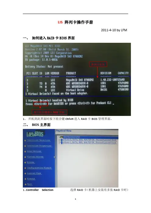
LIS 阵列卡操作手册2011-4-10by LFM一、如何进入RAID 卡BIOS 界面1、开机到此界面时按下组合键Ctrl+H 进入RAID 卡BIOS 管理界面。
二、BIOS主界面1、Controller Selection 选择RAID 卡(机器上安装有多张RAID 卡时)按下组合键进入BIOS 界面阵列卡信息2、Controller Properties RAID卡属性设置3、Scan Devices刷新硬盘设备,4、Virtual Drives虚拟磁盘管理,设置阵列引导顺序-选择要引导的阵列-选择-set boot drive〔currnet=0〕后点GO5、Drives物理硬盘管理6、Configuration Wizard创建阵列配置(配置向导)7、Logical View/Physical View查看逻辑/物理磁盘(点击切换)8、Events事件日志9、Exit退出三、创建阵列1、查看物理硬盘在界面右面可看到可用于做RAID的硬盘○1Slot:0——为硬盘的物理位置,在0号端口。
○2Unconfigured Good——好的,未配置的硬盘。
2、点击“Configuration Wizard ”进入创建阵列配置,如图:12○1Clear Configuration清除所有的阵列配置信息○2New Configuration新建RAID配置(会清除所有的数据,一般只在新机器第一次做阵列时选择)○3Add Configuration曾加RAID配置3、一般选择Add Configuration,按Nex t 进入下一步:12○1Manual Configuration手动配置○2Automatic Configuration自动配置3、选Manual Configuration 手动配置进入下一步:12○1在左边“Drives”框中选择要做RAID的磁盘,按住Ctrl键可一次同时几个。