
ED1202DS;ED1203DS;ED1204DS;ED1205DS;ED1206DS;中文规格书,Datasheet资料
- 格式:pdf
- 大小:513.82 KB
- 文档页数:2
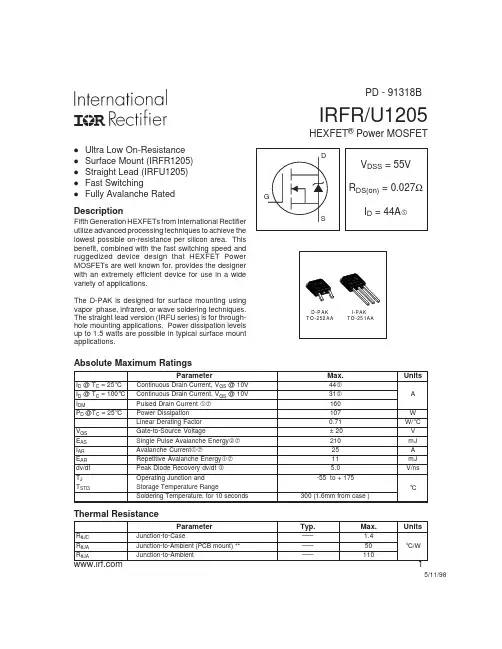
IRFR/U1205HEXFET ®Power MOSFETDescription5/11/98ParameterMax.UnitsI D @ T C = 25°C Continuous Drain Current, V GS @ 10V 44 I D @ T C = 100°C Continuous Drain Current, V GS @ 10V 31 A I DMPulsed Drain Current 160P D @T C = 25°C Power Dissipation 107W Linear Derating Factor 0.71W/°C V GS Gate-to-Source Voltage± 20V E AS Single Pulse Avalanche Energy 210mJ I AR Avalanche Current25A E AR Repetitive Avalanche Energy 11mJ dv/dt Peak Diode Recovery dv/dt 5.0V/ns T J Operating Junction and-55 to + 175T STGStorage Temperature RangeSoldering Temperature, for 10 seconds300 (1.6mm from case )°CAbsolute Maximum RatingsParameterTyp.Max.UnitsR θJC Junction-to-Case––– 1.4R θJA Junction-to-Ambient (PCB mount) **–––50°C/WR θJAJunction-to-Ambient–––110Thermal ResistanceD -P AK T O -252AA I-PA K TO -251AAl Ultra Low On-Resistance l Surface Mount (IRFR1205)l Straight Lead (IRFU1205)l Fast SwitchinglFully Avalanche RatedFifth Generation HEXFETs from International Rectifier utilize advanced processing techniques to achieve the lowest possible on-resistance per silicon area. This benefit, combined with the fast switching speed and ruggedized device design that HEXFET Power MOSFETs are well known for, provides the designer with an extremely efficient device for use in a wide variety of applications.The D-PAK is designed for surface mounting using vapor phase, infrared, or wave soldering techniques.The straight lead version (IRFU series) is for through-hole mounting applications. Power dissipation levels up to 1.5 watts are possible in typical surface mount applications.PD - 91318BIRFR/U1205IRFR/U1205IRFR/U1205IRFR/U1205IRFR/U1205IRFR/U1205IRFR/U1205IRFR/U1205IRFR/U1205。
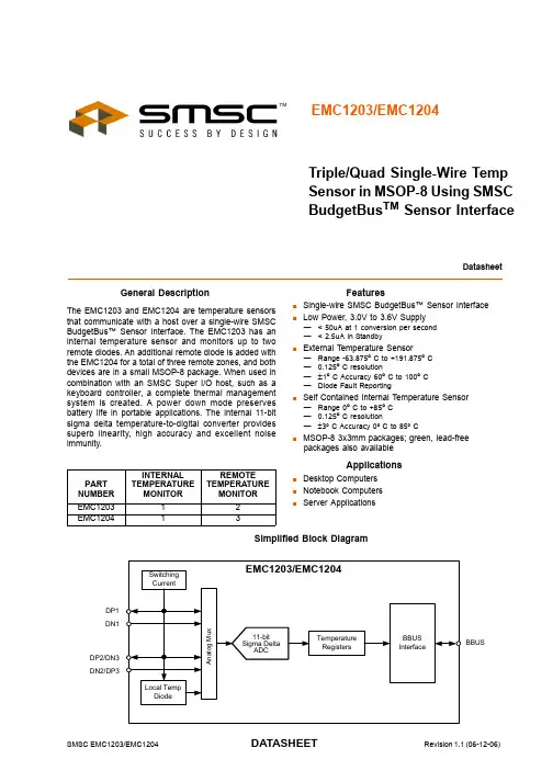
SMSC EMC1203/EMC1204DATASHEETRevision 1.1 (06-12-06)DatasheetEMC1203/EMC1204Triple/Quad Single-Wire Temp Sensor in MSOP-8 Using SMSC BudgetBus TM Sensor InterfaceGeneral DescriptionThe EMC1203 and EMC1204 are temperature sensors that communicate with a host over a single-wire SMSC BudgetBus™ Sensor Interface. The EMC1203 has an internal temperature sensor and monitors up to two remote diodes. An additional remote diode is added with the EMC1204 for a total of three remote zones, and both devices are in a small MSOP-8 package. When used in combination with an SMSC Super I/O host, such as a keyboard controller, a complete thermal management system is created. A power down mode preserves battery life in portable applications. The internal 11-bit sigma delta temperature-to-digital converter provides superb linearity, high accuracy and excellent noise immunity.FeaturesSingle-wire SMSC BudgetBus™ Sensor InterfaceLow Power, 3.0V to 3.6V Supply—< 50uA at 1 conversion per second —< 2.5uA in StandbyExternal Temperature Sensor—Range -63.875º C to +191.875º C —0.125º C resolution—±1º C Accuracy 60º C to 100º C—Diode Fault ReportingSelf Contained Internal Temperature Sensor —Range 0º C to +85º C —0.125º C resolution—±3º C Accuracy 0º C to 85º CMSOP-8 3x3mm packages; green, lead-free packages also availableApplicationsDesktop Computers Notebook ComputersServer ApplicationsSimplified Block DiagramPART NUMBER INTERNAL TEMPERATURE MONITORREMOTE TEMPERATURE MONITOREMC120312EMC120413ORDER NUMBER(S):EMC1203-ACZL-TR IN 8 PIN MSOP PACKAGE (GREEN, LEAD-FREE)EMC1204-ACZL-TR IN 8 PIN MSOP PACKAGE (GREEN, LEAD-FREE)Reel size is 4,000 pieces.Evaluation Board available upon request. (EVB-KBC1100)80 ARKAY DRIVE, HAUPPAUGE, NY 11788 (631) 435-6000, FAX (631) 273-3123Copyright © 2006 SMSC or its subsidiaries. All rights reserved.Circuit diagrams and other information relating to SMSC products are included as a means of illustrating typical applications. Consequently, complete information sufficient for construction purposes is not necessarily given. Although the information has been checked and is believed to be accurate, no responsibility is assumed for inaccuracies. SMSC reserves the right to make changes to specifications and product descriptions at any time without notice. Contact your local SMSC sales office to obtain the latest specifications before placing your product order. The provision of this information does not convey to the purchaser of the described semiconductor devices any licenses under any patent rights or other intellectual property rights of SMSC or others. All sales are expressly conditional on your agreement to the terms and conditions of the most recently dated version of SMSC's standard Terms of Sale Agreement dated before the date of your order (the "Terms of Sale Agreement"). The product may contain design defects or errors known as anomalies which may cause the product's functions to deviate from published specifications. Anomaly sheets are available upon request. SMSC products are not designed, intended, authorized or warranted for use in any life support or other application where product failure could cause or contribute to personal injury or severe property damage. Any and all such uses without prior written approval of an Officer of SMSC and further testing and/or modification will be fully at the risk of the customer. Copies of this document or other SMSC literature, as well as the Terms of Sale Agreement, may be obtained by visiting SMSC’s website at . SMSC is a registered trademark of Standard Microsystems Corporation (“SMSC”). Product names and company names are the trademarks of their respective holders.SMSC DISCLAIMS AND EXCLUDES ANY AND ALL WARRANTIES, INCLUDING WITHOUT LIMITATION ANY AND ALL IMPLIED WARRANTIES OF MERCHANTABILITY, FITNESS FOR A PARTICULAR PURPOSE, TITLE, AND AGAINST INFRINGEMENT AND THE LIKE, AND ANY AND ALL WARRANTIES ARISING FROM ANY COURSE OF DEALING OR USAGE OF TRADE. IN NO EVENT SHALL SMSC BE LIABLE FOR ANY DIRECT, INCIDENTAL, INDIRECT, SPECIAL, PUNITIVE, OR CONSEQUENTIAL DAMAGES; OR FOR LOST DATA, PROFITS, SAVINGS OR REVENUES OF ANY KIND; REGARDLESS OF THE FORM OF ACTION, WHETHER BASED ON CONTRACT; TORT; NEGLIGENCE OF SMSC OR OTHERS; STRICT LIABILITY; BREACH OF WARRANTY; OR OTHERWISE; WHETHER OR NOT ANY REMEDY OF BUYER IS HELD TO HAVE FAILED OF ITS ESSENTIAL PURPOSE, AND WHETHER OR NOT SMSC HAS BEEN ADVISED OF THE POSSIBILITY OF SUCH DAMAGES.Triple/Quad Single-Wire Temp Sensor in MSOP-8 Using SMSC BudgetBus TM Sensor Interface DatasheetRevision 1.1 (06-12-06)ii SMSC EMC1203/EMC1204DATASHEETTriple/Quad Single-Wire Temp Sensor in MSOP-8 Using SMSC BudgetBus TM Sensor InterfaceDatasheetSMSC EMC1203/EMC12041Revision 1.1 (06-12-06)DATASHEETChapter 1 Pin ConfigurationFigure 1.1 EMC1203 and EMC1204 Pin Configuration1.1 Pin DescriptionTable 1.1 EMC1203 and EMC1204 Pin DescriptionPIN PIN NO.DESCRIPTIONDP11Positive Analog Connection to External Temperature Diode 1DN12Negative Analog Connection to External Temperature Diode 1DN2/DP33Negative Analog Connection to External Temperature Diode 2Positve Analog Connection to External Temperature Diode 3, EMC1204 only DP2/DN34Positve Analog Connection to External Temperature Diode 2Negative Analog Connection to External Temperature Diode 3, EMC1204 only BBUS 5Serial Bus Interface to BBUS HostSCLK 6Normally GND, this pin may be configured to source a synchronous clock.GND 7GroundVDD8Supply Voltage VDDTriple/Quad Single-Wire Temp Sensor in MSOP-8 Using SMSC BudgetBus TM Sensor InterfaceDatasheetRevision 1.1 (06-12-06)2SMSC EMC1203/EMC1204DATASHEET1.2 Absolute Maximum RatingsNote:Stresses above those listed could cause damage to the device. This is a stress rating onlyand functional operation of the device at any other condition above those indicated in the operation sections of this specification is not implied. When powering this device from laboratory or system power supplies, it is important that the Absolute Maximum Ratings not be exceeded or device failure can result. Some power supplies exhibit voltage spikes on their outputs when the AC power is switched on or off. In addition, voltage transients on the AC power line may appear on the DC output. If this possibility exists, it is suggested that a clamp circuit be used.Table 1.2 EMC1203 and EMC1204 Maximum Ratings DESCRIPTIONRATING UNIT Supply Voltage V DD -0.3 to 5.0V Voltage on any other pin -0.3 to V DD +0.3V Operating Temperature Range 0 to 85°C Storage Temperature Range -55 to 150°CLead Temperature RangeRefer to JEDEC Spec. J-STD-020Package Thermal Characteristics for MSOP-8Power DissipationTBD Thermal Resistance(at 0 air flow)109.6°C/W ESD Rating, All Pins Human Body Model2000VTriple/Quad Single-Wire Temp Sensor in MSOP-8 Using SMSC BudgetBus TM Sensor InterfaceDatasheetSMSC EMC1203/EMC12043Revision 1.1 (06-12-06)DATASHEETChapter 2 Electrical CharacteristicsTable 2.1 Electrical CharacteristicsV DD =3.0V to 3.6V, T A = 0°C to +85°C, Typical values at T A = 27°C unless otherwise notedPARAMETERSYMBOL MIN TYP MAX UNITS CONDITIONSDC Power Supply VoltageV DD 3.0 3.3 3.6V Average Operating CurrentI DD 600650μA Active mode (continuous)I PD1.82.5μAStandby modeInternal Temperature Measurement Accuracy±1±3°C0°C ≤T A ≤85°CExternal Temperature Measurement Temperature AccuracyRemote Diode 60°C to 100°C Remote Diode 0°C to 125°C Remote Diode 0°C to 125°C ± 1± 3TBD°C °C °C15°C ≤T A ≤70°C 0°C ≤T A ≤85°C -40°C ≤T A ≤125°CADC Resolution0.125°C Conversion Time per sensor20msTriple/Quad Single-Wire Temp Sensor in MSOP-8 Using SMSC BudgetBus TM Sensor InterfaceDatasheetRevision 1.1 (06-12-06)4SMSC EMC1203/EMC1204DATASHEETChapter 3 Product DescriptionThe EMC1203 and EMC1204 are temperature sensors with a proprietary single wire SMSC BudgetBus™ Sensor Interface. Temperature information is communicated to a host device via the serial bus. All intelligence regarding the interpretation of temperature resides in the host. Figure 3.1,"System Overview" shows a typical system overview:Figure 3.1 System OverviewIn cooperation with the host device, thermal management can be performed as shown in Figure 3.1.Thermal management consists of the host acquiring the temperature data from the EMC1203 and EMC1204 controlling the speed of one or more fans. The host has the ability to compare measured temperature levels to preset limits and take the appropriate action when values are found to be out of limit. The EMC1203 and the DP1/DN1 port of the EMC1204 are compatible with CPU substrate diodes.Two separate temperature zones are monitored using only two pins on the EMC1204. This is accomplished using two anti-parallel diodes as shown on the pins DP2/DN3 and DN2/DP3 in Figure 3.1. This technique maintains high accuracy while minimizing pin count and reducing board routing complexity. The anti-parallel diode architecture performs very well with diode connected transistors. It is not compatible with substrate transistors (sometimes called thermal diodes or on-chip sense junctions).3.1 Temperature MonitorsThermal diode temperature measurements are based on the change in forward bias voltage (ΔV BE ) of a diode when operated at two different currents:The change in ΔV BE voltage is proportional to absolute temperature T.where:k = Boltzmann’s constantT = absolute temperature in Kelvin q = electron chargeη = diode ideality factorTriple/Quad Single-Wire Temp Sensor in MSOP-8 Using SMSC BudgetBus TM Sensor InterfaceDatasheetSMSC EMC1203/EMC12045Revision 1.1 (06-12-06)DATASHEETFigure 3.2 Detailed Block Diagram of Temperature Monitor ArchitectureFigure 3.2 shows a detailed block diagram of the temperature measurement circuit. As shown, the EMC1203 and EMC1204 incorporates switched capacitor technology that samples the temperature diode voltage at two bias currents and holds the difference voltage. The sample frequency is 100kHz and the current levels Ihigh and Ilow are 170uA and 10uA respectively.The output of the switched capacitor sample and hold circuit interfaces to a single bit delta sigma analog to digital converter. This ADC runs at 100kHz sample frequency and its output is digitally filtered and averaged over 2048 samples effectively generating 11 bit accuracy.The advantages of this architecture over Nyquist rate FLASH or SAR converters are superb linearity and inherent noise immunity. The linearity can be directly attributed to the delta sigma ADC single bit comparator while the noise immunity is achieved by the digital averaging filter. The overall effective bandwidth of the system is fs/2048 which translates to a 50Hz bandwidth at 100kHz sample rate.Conversion time equals about 20ms per temperature monitor.3.1.1EMC1203 Temperature MonitoringThe EMC1203, incorporates one internal diode and can monitor two additional temperature zones with two external diodes.An internal analog multiplexer switches between the internal and external diodes.Total conversion time for one internal and two external temperature readings is about 60ms. The external diodes can be either a CPU substrate diode or a discrete diode connected transistor like the 2N3904 or 2N3906. External diode connected transistors examples are shown in Figure 3.3:Figure 3.3 EMC1203 External Diode Examples3.1.2EMC1204 Temperature MonitoringThe EMC1204, incorporates one internal diode and can monitor three external diodes. Total conversion time for one internal and three external temperature reading is 80ms. An internal multiplexer switches between internal and external diodes. The external thermal diode connected to DP1 and DN1 canTriple/Quad Single-Wire Temp Sensor in MSOP-8 Using SMSC BudgetBus TM Sensor InterfaceDatasheetRevision 1.1 (06-12-06)6SMSC EMC1203/EMC1204DATASHEETeither be a CPU substrate diode or a regular thermal diode-connected transistor. External diodes at DP2/DN3 and DN2/DP3 have to be connected in an anti-parallel fashion. Because of this, one diode will be forward biased while the other is reverse biased and therefore it is recommended to connect only discrete thermal diodes to these pins.Do not use the anti-parallel interface (DP2/DN3 and DN2/DP3) to connect substrate transistors (sometimes called thermal diodes or on-chip sense junctions). External diode connected transistors examples are shown in Figure 3.4Figure 3.4 EMC1204 External Diode Examples3.2 SMSC BudgetBus™ Sensor InterfaceThe EMC1203 and EMC1204 series of temperature monitors communicate with a host controller, such as the KBC1100, through the SMSC BudgetBus™ Sensor Interface. The BBUS is a single wire serial communication protocol between the computer host and its peripheral devices. Please refer to the SMSC BudgetBus™ Sensor Interface Specification for detailed information about the modes of operation.3.3 Power ModesThe EMC1203 and EMC1204 have two basic modes of operation:Standby Mode:The host can initiate standby mode by actively pulling the BBUS low. When the Host places the device in standby mode, the device immediately powers down to draw < 2uA of supply current. It will remain in this state until it is awakened by the host. If the host pulls the BBUS line low while temperature data is being clocked out, the device will not enter standby mode until completion of the data transfer. After entering standby mode, the device will remain in this mode until it is forced into active mode by the host. The transition from standby to active mode occurs when the host is no longer pulling the BBUS low.Active Mode:The host initiates active mode by enabling a weak pull up on the BBUS. In this mode, the EMC1203and EMC1204 continuously convert temperature data. During the time that the device is actively converting a temperature, the BBUS is in tri-state mode, and the Host places a weak pull-up on the bus to prevent it from floating. After a conversion is completed, the device automatically clocks out the data from the most recent conversion to the host. When the data packet has been entirely clocked out,the BBUS returns to tri-state mode, and the ADC begins converting the next temperature sample.While BBUS is in tri-state mode, the host can command the device to standby mode.Triple/Quad Single-Wire Temp Sensor in MSOP-8 Using SMSC BudgetBus TM Sensor InterfaceDatasheetSMSC EMC1203/EMC12047Revision 1.1 (06-12-06)DATASHEET3.4 Temperature Data FormatTemperature readings are coded in 2’s complement format with a -64ºC offset. This format spans from –63.875ºC to +191.875ºC with 0.125ºC resolution. A temperature measurement outside this range is reported as either –63.875ºC or +191.875ºC. The host must add 64ºC to calculate the actual temperature. Table 3.1 shows example temperature readings and the value that will be reported on the BBUS.As shown in Table 3.1, 400h is reserved for diode fault signaling which occurs when open or short conditions are detected between the external DP and DN pins.3.5 Conversion RateThe conversion rate can be controlled by the host. This is accomplished by periodically placing the device in standby as described in Section 3.3.Table 3.1 Temperature Data FormatACTUAL TEMP.(ºC)2’S COMPLEMENT OF -64ºC OFFSET HEX Diode Fault 100 0000 0000400-63.875100 0000 0001401-63.000100 0000 1000408-1.000101 1111 10005F80.000110 0000 0000600+0.125110 0000 0001601+1.000110 0000 1000608Triple/Quad Single-Wire Temp Sensor in MSOP-8 Using SMSC BudgetBus TM Sensor InterfaceDatasheetRevision 1.1 (06-12-06)8SMSC EMC1203/EMC1204DATASHEETChapter 4 Package OutlineFigure 4.1 8-Pin MSOP Package Outline - 3x3mm Body 0.65mm PitchNotes:1.Controlling Unit: millimeters.2.Tolerance on the true position of the leads is ± 0.065 mm maximum.3.Package body dimensions D and E1 do not include mold protrusion or flash. Dimensions D andE1 to be determined at datum plane H. Maximum mold protrusion or flash is 0.15mm (0.006 inches)per end, and 0.15mm (0.006 inches) per side.4.Dimension for foot length L measured at the gauge plane 0.25 mm above the seating plane.5.Details of pin 1 identifier are optional but must be located within the zone indicated.Table 4.1 8-Pin MSOP Package ParametersMINNOMINALMAX REMARKS A 0.80~ 1.10Overall Package HeightA10.05~0.15Standoff A20.750.850.95Body Thickness D 2.80 3.00 3.20X Body Size E 4.65 4.90 5.15Y Span E1 2.80~ 3.20Y body Size H 0.08~0.23Lead Foot Thickness L 0.40~0.80Lead Foot Length L10.95 REF Lead Length e0.65 BSCLead Pitch θ0o ~8o Lead Foot Angle W 0.22~0.38Lead Width ccc~~0.10Coplanarity。

