LIS协议接口手册(中文)
- 格式:pdf
- 大小:664.70 KB
- 文档页数:96


环迅支付(IPS)系统接口定义说明手册文档修订记录目录1.简介 (1)1.1.背景简介 (1)1.2.IPS支付流程 (1)1.2.1.银行卡支付基本流程图 (1)2.安全控制 (2)2.1.防火墙 (2)2.2.SSL128位传输加密标准 (3)2.3.订单支付接口的MD5摘要认证 (3)2.4.交易返回接口的数字签名认证 (3)3.系统环境要求 (4)3.1.硬件环境 (4)3.2.软件环境 (4)3.3.网络环境 (4)3.4阅读对象 (4)4.接口开发 (5)4.1.开发前准备工作 (5)4.1.1消息请求头定义 (5)4.1.2消息响应头定义 (6)4.1.3消息数字签名 (6)4.2.订单支付 (7)4.2.1表单提交(POST方式) (7)4.2.2.订单提交URL (8)4.2.3.订单支付接口表单参数 (9)4.3.订单支付返回 (10)4.3.1.表单返回 (10)4.3.2.交易返回接口表单参数 (11)4.3.3.交易返回接口验证事项 (12)4.4.订单查询(W EB S ERVICE) (13)4.4.1按商户订单号查询 (13)4.4.2按银行订单号查询 (15)4.4.3按商户订单时间查询 (18)4.5.交易查询(W EB S ERVICE) (21)4.5.1按IPS交易流水号查询 (21)4.5.2按IPS交易时间查询 (23)4.6.交易退款(W EB S ERVICE) (25)4.6.1 服务地址 (25)4.6.2 请求 (25)4.6.3 响应 (26)附录 (27)交易返回方式 (27)交易类型表 (28)币种列表 (29)错误返回码 (29)银行列表 (1)1. 简介1.1. 背景简介IPS(Internet Payment System)是一个功能强大基于网络的在线支付平台,由IPS投入大量资金和科研力量开发而成,以其自身个性化的设计为客户提供了多渠道、多语言、更安全的在线支付服务。
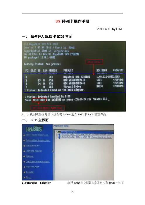
LIS 阵列卡操作手册2011-4-10by LFM一、如何进入RAID 卡BIOS 界面1、开机到此界面时按下组合键Ctrl+H 进入RAID 卡BIOS 管理界面。
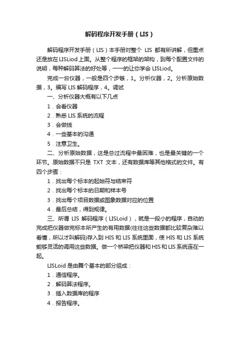
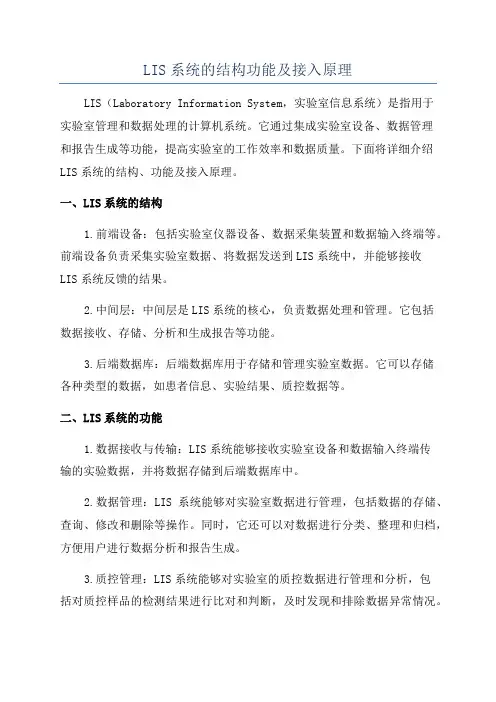
二、BIOS主界面1、Controller Selection 选择RAID 卡(机器上安装有多张RAID 卡时)按下组合键进入BIOS 界面阵列卡信息2、Controller Properties RAID卡属性设置3、Scan Devices刷新硬盘设备,4、Virtual Drives虚拟磁盘管理,设置阵列引导顺序-选择要引导的阵列-选择-set boot drive〔currnet=0〕后点GO5、Drives物理硬盘管理6、Configuration Wizard创建阵列配置(配置向导)7、Logical View/Physical View查看逻辑/物理磁盘(点击切换)8、Events事件日志9、Exit退出三、创建阵列1、查看物理硬盘在界面右面可看到可用于做RAID的硬盘○1Slot:0——为硬盘的物理位置,在0号端口。
○2Unconfigured Good——好的,未配置的硬盘。
2、点击“Configuration Wizard ”进入创建阵列配置,如图:12○1Clear Configuration清除所有的阵列配置信息○2New Configuration新建RAID配置(会清除所有的数据,一般只在新机器第一次做阵列时选择)○3Add Configuration曾加RAID配置3、一般选择Add Configuration,按Nex t 进入下一步:12○1Manual Configuration手动配置○2Automatic Configuration自动配置3、选Manual Configuration 手动配置进入下一步:12○1在左边“Drives”框中选择要做RAID的磁盘,按住Ctrl键可一次同时几个。
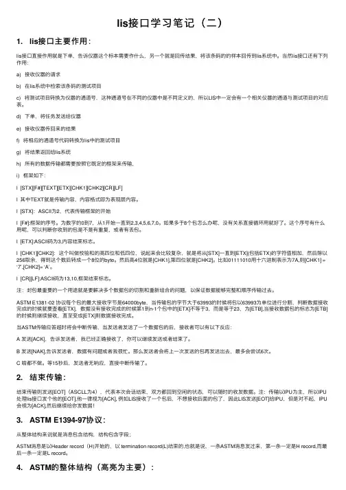
解码程序开发手册(LIS)解码程序开发手册(LIS)本手册对整个LIS都有所讲解,但重点还是放在LISLiod上面。
从整个程序的框架的架构,到每个配置文件的说明,每种解码算法的好处等,一一的让你学会LISLiod。
完成一台仪器,一般是四个步镞,1。
分析仪器,2。
分析原始数据,3。
编写LIS解码程序,4。
调试一、分析仪器大概有以下几点1.会看仪器2.熟悉LIS系统的流程3.会做线4.一些基本的沟通5.注意卫生。
二、分析原始数据,这是总过流程中最困难,也是最关键的一个环节。
原始数据不只是TXT文本,还有数据库等其他格式的文件。
有四个步骤:1.找出每个标本的起始符与结束符2.找出每个标本的日期和样本号3.找出每个项目数据或图象数据对应的位置4.最后总结,得到规律。
三、所谓LIS解码程序(LISLoid),就是一段小的程序,自动的完成把仪器做完标本所产生的有用数据(往往这些数据都比较复杂难以看懂,所以才叫解码)存入到HIS和LIS系统里面,使HIS和LIS系统能够灵活的调用这些数据。
做一个桥梁把仪器和HIS和LIS系统连在一起。
LISLoid是由舞个基本的部分组成:1.通信程序。
2.解码算法程序。
3.插入数据库的程序4.报告程序。
5.历史备份四、调试,除了完善LISLiod,还有报表格式的调整,打印机等测试。
分析仪器1.会看仪器,不是要你学会怎样使用仪器,而是根据实际的情况把这台仪器定位到我们解决它的四个位置中,哪四一个位置?第一,仪器已经很旧,一些取数据的接口已经损坏,使用次数很少。
象这类型的仪器迟早会要淘汰去,做了意义也不大,所以对这些仪器我们采用“手工项目”,直接手工填写数据,保存到LIS系统,解码程序也就省了。
第二,中小型的仪器,一般都是有COM接口的,标本的样本号由仪器本身输出。
对这种我们用通信程序直接截取数据进行解码。
(如:电解质仪器,尿液分析仪。
)第三,很先进的大仪器,这种一般都比较复杂,就算能用通信程序截取到数据,我们对它进行完全解码也比较困难,而仪器一般都自带有一套操作软件,所以我们从它的软件中做接口,大部分仪器在这方面都留有接口,可以找说明书,也可以直接打电话询问仪器产家。

声明版权所有 © 浙江齐治科技股份有限公司 2019。
保留一切权利。
非经本公司书面许可,任何单位和个人不得擅自摘抄、复制本文档内容的部分或全部,并不得以任何形式传播。
商标声明•是浙江齐治科技股份有限公司的商标或注册商标。
•本文档提及的其他所有商标或注册商标,由各自的所有人拥有。
注意您购买的产品、服务或特性等应受浙江齐治科技股份有限公司商业合同和条款的约束,本文档中描述的全部或部分产品、服务或特性可能不在您的购买或使用范围之内。
除非合同另有约定,浙江齐治科技股份有限公司对本文档内容不做任何明示或默示的声明或保证。
由于产品版本升级或其他原因,本文档内容会不定期进行更新。
除非另有约定,本文档仅作为使用指导,本文档中的所有陈述、信息和建议不构成任何明示或暗示的担保。
关于本文档本文档详细介绍RIS的各种功能特性,内容包括RIS的特性介绍和操作指导。
本文档适用于RIS的管理员和操作员等多种用户角色,请根据自己的操作角色,参考权限列表,阅读相应的指导,或者在实际操作中有疑问时查阅本文档。
产品版本与本文档相对应的产品和版本如下表所示。
产品名称产品版本齐治科技RIS数据中心风险洞察系统 3.3.7格式约定格式说明粗体各类界面控件名称采用加粗字体表示,如单击确定。
>多级菜单用 > 隔开。
如选择用户管理 > 用户列表,表示选择用户管理菜单下的用户列表子菜单。
目录声明............................................................................................................................................................................................序言 关于本文档......................................................................................................................................................................插图清单 (ix)表格清单 (x)第 1 章 概述 (1)操作角色 (1)权限列表 (2)登录方式 (3)登录RIS Web界面 (3)登录RIS的Console (9)通过RDP登录RIS (15)通过SSH登录RIS (18)安装安全证书 (20)安装AccessClient (21)获取帮助 (21)获取软件版本信息 (21)管理软件包和用户手册 (21)第 2 章 用户管理 (23)配置用户(手工创建) (24)配置用户(批量导入) (27)配置用户(LDAP导入) (30)修改用户属性 (32)修改单个用户的属性 (32)批量修改多个用户的属性 (33)查看用户 (34)配置用户组 (36)第 3 章 资产管理 (38)配置资产 (40)配置资产(手工创建) (40)配置资产(批量导入) (44)配置资产的访问协议 (51)配置资产的帐号和密码 (53)配置资产组 (58)查看资产 (58)查看动态视图 (59)配置视图的层级 (61)配置Windows域 (62)配置密钥 (63)生成新密钥 (64)粘贴已有密钥 (64)配置等价资产 (64)配置等价帐号 (66)配置资产适配 (66)客户端代填兼容性列表 (68)第 4 章 权限管理 (71)配置权限 (72)配置动态权限 (72)配置变更单 (74)配置规则模板 (75)查看权限 (79)按用户查看权限 (79)按资产查看权限 (79)配置高危操作 (79)复核高危操作 (80)查看已复核操作 (81)配置会话复核 (83)配置高危命令 (86)配置命令模板 (89)第 5 章 资产访问 (92)查找资产 (93)建立会话 (94)通过Web界面建立会话 (94)通过Mstsc客户端建立图形会话 (98)通过Telnet/SSH客户端建立字符会话 (100)共享会话 (101)发起共享 (102)加入共享 (102)传输文件 (103)通过Web界面建立SFTP会话传输文件 (104)通过SFTP工具直连目标资产传输文件 (104)在字符终端中通过SFTP传输文件 (106)在字符会话中通过ZMODEM传输文件 (106)在RDP图形会话中通过剪贴板传输文件 (107)在RDP图形会话中通过磁盘映射传输文件 (108)执行高危操作 (108)客户端兼容性列表 (110)第 6 章 审计 (115)查看审计概览与统计 (116)查看审计数据概览 (116)查看会话情况统计 (117)检索问题 (118)查看审计结果(操作类) (121)审计在线会话 (121)审计字符会话 (122)审计图形会话 (124)审计数据库会话 (126)审计文件传输 (128)查看审计结果(事件类) (129)审计登录日志 (129)审计配置日志 (130)查看审计记录 (131)播放会话录屏 (132)数据库审计兼容性列表 (134)第 7 章 报表 (136)配置报表 (136)查看历史报表 (138)配置报表模板 (139)配置报表参数 (139)第 8 章 自动化 (141)配置脚本任务 (141)查看脚本任务执行历史和结果 (143)第 9 章 工单 (146)新建资产权限申请工单 (147)新建密码申请工单 (149)审批待办工单 (152)查看(撤销)已办工单 (152)配置审批模板 (153)第 10 章 帐号改密 (156)管理帐号资产 (156)设置帐号属性 (156)管理选定帐号密码 (157)查看选定帐号日志 (159)批量更新帐号 (159)批量导出帐号 (160)帐号维护 (160)配置改密计划 (160)配置密码备份 (165)日志报表 (166)查看历史密码 (166)系统设置 (167)配置密码规则 (167)配置改密方法 (170)第 11 章 个人帐号相关设置 (175)修改个人设置 (175)设置基本信息 (175)修改密码 (176)修改语言设置 (176)设置操作员默认展示页面 (176)配置信息加密 (177)配置ZIP文件密码 (177)配置PGP公钥 (177)修改会话配置 (178)修改字符会话配置 (178)修改图形会话配置 (179)修改文件传输配置 (181)配置密钥 (181)查看访问记录 (182)第 12 章 系统设置 (184)系统 (184)基本设置:配置网络参数 (184)基本设置:配置系统时间 (187)基本设置:配置邮件服务 (188)基本设置:配置文件服务 (188)基本设置:配置告警事件 (190)基本设置:配置短信网关和发送通知短信的功能 (193)基本设置:备份系统配置 (195)基本设置:配置logo (196)基本设置:修改服务端口 (196)基本设置:修改配置文件 (197)基本设置:配置其他系统基本参数 (197)配置部门 (200)配置HA (200)配置共享登录 (202)配置授权文件 (206)升级系统和安装补丁 (206)查看系统状态 (206)配置安全证书 (208)定期任务:配置LDAP用户同步 (209)定期任务:配置审计数据备份 (210)定期任务:配置审计数据清理 (211)配置问题诊断 (212)用户 (214)登录认证:配置本地密码参数 (214)登录认证:配置AD认证 (214)登录认证:配置LDAP认证 (216)登录认证:配置RADIUS认证 (217)登录认证:配置动态令牌认证(TOTP) (218)登录认证:配置手机令牌认证 (220)登录认证:配置短信认证 (220)登录认证:配置双因子认证 (221)登录认证:配置X.509证书认证 (221)登录认证:配置USB Key认证 (222)登录认证:配置登录安全 (223)配置用户角色权限 (224)配置用户属性 (225)配置全局用户登录控制 (225)资产 (226)配置资产类型 (226)配置资产属性 (229)访问设置 (230)远程客户端 (236)第 13 章 Console控制台 (240)配置系统日期和时间(Date and Time) (240)配置HA(HA Management) (241)设置HA维护模式 (241)拆除HA (242)查看系统信息(System Maintenance) (242)配置网络参数(Network Configuration) (243)修改网口信息 (243)修改路由配置 (244)查看/修改网口状态 (244)配置网口绑定 (245)配置默认网关 (246)配置IPv6默认网关 (247)关闭/开启IPv6路由通告 (248)配置主机名信息 (248)添加网口 (249)使用Shterm工具(Shterm Tools) (249)一键采集日志 (249)安装标准升级包和补丁包 (250)安装其他特殊补丁包 (250)恢复出厂设置 (251)修复RPM Database (251)重置admin用户(Reset admin) (251)配置SSHD端口状态(SSHD Management) (252)配置Host头防护(Nginx Management) (252)配置访问控制(ACL Management) (253)使用系统工具(System Tools) (254)图 1: 菜单布局的动态视图 (60)图 2: 树形布局的动态视图 (60)图 3: 编辑权限规则模板 (76)图 4: 命令权限检查流程图 (86)图 5: 资产权限工单处理流程 (147)图 6: 密码工单处理流程 (150)图 7: 改密流程图 (161)图 8: HA组网 (200)图 9: 直接访问的资产类型 (227)表 1: 用户手册上传要求说明表 (22)表 2: 软件包上传要求说明表 (22)表 3: 预定义用户属性 (23)表 4: 主机资产 (38)表 5: 网络资产 (38)表 6: 数据库资产 (38)表 7: 应用系统资产 (39)表 8: 常见资产属性 (39)表 9: 访问协议参数说明 (51)表 10: 资产的帐号和密码参数(手工批量导入) (54)表 11: 资产的帐号和密码参数(手工配置) (56)表 12: 树形布局动态视图按钮说明 (60)表 13: 预览视图按钮说明 (62)表 14: 等价资产的组成条件和同步的配置 (65)表 15: 客户端代填兼容性列表 (69)表 16: 动态权限匹配方式说明 (72)表 17: 主机/网络设备支持的不同协议类型的前提条件 (94)表 18: 配置会话参数 (96)表 19: 配置Mstsc客户端图形会话参数 (99)表 20: 字符会话常用操作 (100)表 21: 不同文件传输方式的比较 (103)表 22: 客户端兼容性列表 (111)表 23: 字符会话建议使用的客户端列表 (111)表 24: 登录Console控制台建议使用的客户端列表 (113)表 25: mstsc建议版本 (113)表 26: 数据库审计兼容性列表 (134)表 27: 目标资产和脚本支持情况 (141)表 28: 系统预置命令表 (142)表 29: 常见错误信息和可能原因 (144)表 30: 工单申请人、使用人和审批人的要求 (146)表 31: 支持帐号扫描的资产类型和要求 (162)表 32: 常用MIB节点 (198)表 33: 审计数据备份文件说明 (210)表 34: 动态令牌参数说明 (218)表 35: 资产属性类型说明 (229)概述1目录:•操作角色•权限列表•登录方式•安装安全证书•安装AccessClient •获取帮助操作角色RIS为了解决用户身份识别问题,为每一个用户创建一个身份认证帐号,用于平台身份鉴别,并借助访问权限将平台身份帐号与相应资产中系统帐号一一关联,实现用户操作与其身份相关联。
lis接⼝学习笔记(⼆)1. lis接⼝主要作⽤:lis接⼝直接作⽤就是下单,告诉仪器这个标本需要作什么,另⼀个就是回传结果,将该条码的的样本回传到lis系统中。
当然lis接⼝还有下列作⽤:a) 接收仪器的请求b) 在lis系统中检索该条码的测试项⽬c) 将测试项⽬转换为仪器的通道号,这种通道号在不同的仪器中是不同定义的,所以LIS中⼀定会有⼀个相关仪器的通道与测试项⽬的对应表。
d) 下单,将任务发送给仪器e) 接收仪器传回来的结果f) 将相应的通道号代码转换为lis中的测试项⽬g) 将结果返回给lis系统h) 所有的数据传输都需要按照它既定的框架来传输,i) 框架如下:l [STX][F#][TEXT][ETX][CHK1][CHK2][CR][LF]l 其中TEXT就是传输内容,内容格式即为表现层内容。
l [STX]:ASCll为2,代表传输框架的开始l [F#]:框架的序号。
为数字的0到7,从1开始⼀直到2,3,4,5,6,7,0。
如果多于8个包怎么办呢,没有关系直接循环⽤就好了。
这个序号有什么⽤呢,可以判断你收到的包是不是有重复,或者有丢包。
l [ETX]:ASCII码为3,内容结束标志。
l [CHK1][CHK2]:这个叫做校验和的⾼四位和低四位,说起来会⽐较复杂,就是将从[STX]⼀直到[ETX](包括ETX)的字符值相加,然后除以256取余,得到这个数后转成⼀个8位的byte。
然后⾼4位就是[CHK1],第四位就是[CHK2]。
⽐如01111010⽤⼗六进制表⽰为7A,则[CHK1] =‘7’,[CHK2]= ‘A’。
l [CR][LF]:ASCII码为13,10,框架结束标志。
注:封包最重要的⼀个⽤途就是要解决多个数据包的切割和重新组合的问题,以保证数据能够完整和顺序传输过去。
ASTM E1381-02 协议每个包的最⼤接收字节是64000byte,当传输包的字节⼤于63993的时候将包以63993为单位进⾏分割,判断数据接收完成的时候就要查看[ETX],数据没有接收完成的时候第1到n-1个包中的[ETX]不等于3,⽽是等于23,为[ETB],当接收数据包的标志为[ETB]的时候则继续接收,直⾄变成[ETX]则数据接收完成。
帝迈DH5系列 LIS 通信通信操作操作操作说明说明1.1 LIS 软件安装双击LIS 软件的安装程序,选择仪器类型和仪器型号。
帝迈的仪器大类:血球仪仪器型号:帝迈DH5系列或DH56、DH51、DH53,决定于LIS 提供厂商的名称定义。
安装后,请在LIS 软件中网络设置中,设置LIS 监听的IP 地址和端口号。
端口号建议使用5600。
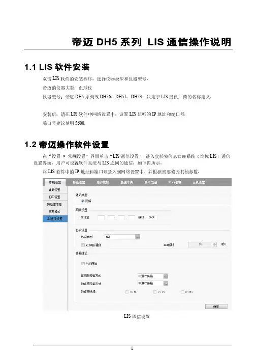
1.2 帝迈操作帝迈操作软件设置软件设置在“设置 > 常规设置”界面单击“LIS 通信设置”,进入实验室信息管理系统(简称LIS )通信设置界面。
用户可设置软件系统与LIS 之间的通信。
如下图所示。
将LIS 软件中的IP 地址和端口号录入到网络设置中,并根据需要修改其他参数。
LIS 通信设置相关参数说明如表所示。
LIS通信设置参数说明参数含义操作通讯类型软件系统与LIS进行通信的类型。
目前软件支持通过网络方式与LIS进行通信。
无。
网络设置IP地址LIS服务器的地址。
请根据实际情况进行设置。
端口LIS服务器的端口,默认为5600。
请根据实际情况进行设置。
协议设置协议类型软件系统与LIS通信使用的协议类型。
默认为HL7。
无ACK同步通信若勾选,则软件系统与LIS通信时,若在“ACK超时”时间内收到LIS的ACK应答,则表示通信成功;若收不到,表示通信失败。
若不勾选,则软件系统与LIS通信时,无论有无收到LIS的ACK应答,都认为通信成功。
说明无论通讯成功与否,软件系统将继续发送下一条消息。
根据实际情况选择。
ACK超时ACK应答的超时时间。
默认为10秒,即如果软件系统在10秒没有收到ACK应答,则认为通信失败。
单击上下箭头或在编辑框中直接输入。
输入范围:0~1000的整数。
单位:秒。
注意仅当“ACK同步通信”勾选时,该参数才有效。
传输模式自动通信若勾选,则样本分析完成后,软件系统自动将结果上传至LIS。
若不勾选,则不自动上传样本分析结果。
根据实际情况选择。
参数含义操作直方图传输方式软件系统对样本结果进行通信时,向LIS传输直方图的方式。
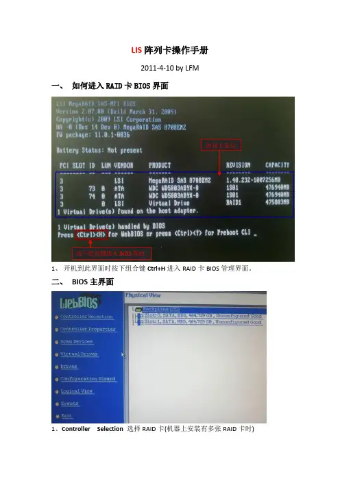
LIS阵列卡操作手册2011-4-10 by LFM一、如何进入RAID卡BIOS界面阵列卡信息按下组合键进入BIOS界面1、开机到此界面时按下组合键Ctrl+H进入RAID卡BIOS管理界面。
二、BIOS主界面1、Controller Selection 选择RAID卡(机器上安装有多张RAID卡时)2、Controller Properties RAID卡属性设置3、Scan Devices 刷新硬盘设备,4、Virtual Drives 虚拟磁盘管理,设置阵列引导顺序-选择要引导的阵列-选择—set boot drive〔currnet=0〕后点GO5、Drives 物理硬盘管理6、Configuration Wizard 创建阵列配置(配置向导)7、Logical View/Physical View查看逻辑/物理磁盘(点击切换)8、Events 事件日志9、Exit 退出三、创建阵列1、查看物理硬盘在界面右面可看到可用于做RAID的硬盘错误!Slot:0——为硬盘的物理位置,在0号端口。
错误!Unconfigured Good-—好的,未配置的硬盘.2、点击“Configuration Wizard”进入创建阵列配置,如图:12错误!Clear Configuration 清除所有的阵列配置信息错误!New Configuration 新建RAID配置(会清除所有的数据,一般只在新机器第一次做阵列时选择)错误!Add Configuration 曾加RAID配置3、一般选择Add Configuration,按Nex t进入下一步:12○,1Manual Configuration 手动配置错误!Automatic Configuration 自动配置3、选Manual Configuration手动配置进入下一步:12错误!在左边“Drives”框中选择要做RAID的磁盘,按住Ctrl键可一次同时几个。

lis接⼝学习笔记(1)1. lis设备的两⼤层⾯:a) 表现层:病⼈信息结果数据表现的结构(封装相应的病⼈信息的,病⼈信息、结果信息等内容);b) 数据连接层:就是数据包,通过打包这些数据,保证这些数据能够完整的传输过去。
传输过去后,再解包这些数据,使得它能够成为⼀个完整的数据(封装传输数据的)。
2. 数据层发送数据的过程:a) 建⽴连接:建⽴连接的实际上要解决两个问题,⼀个是谁是数据发送者,谁是数据接收者。
⼆是,接收者到底忙不忙,有没有空来接收你发送的数据。
b) 数据传输:当发送者和接收者都建⽴连接,准备就绪之后,数据传输要解决的问题是有多少数据的问题。
例如快递员给了你⼀个包裹,再给你⼀个包裹,那到底什么时候给完我,否则我收到的包裹不齐全,就没有办法组成⼀个完整的物品了。
注:所有数据的传输都要按照它既定的框架来传输。
c) 结束连接:当发送者已经没有数据发送的时候,就要告知接收者,你可以⼲其它的去了。
3. 建⽴连接交互过程:a) 建⽴连接后数据发送者发送⼀个询问(ENQ)信号给接收者,告诉他说我要开始发数据了,你准备接收吧,当接收者收到询问信号后它有两种选择:回复⼀个确认消息(ACK)信号后,告诉发送者⾃⼰准备好随时接收你的数据;当然呢也可以回复⼀个⽆应答(NAK)信号,告诉发送者⾃⼰忙,没有准备好。
当接收者回复ACK之后就可以继续往下⾛了,但当接受者发送了NAK之后发送者将等待10秒继续发送ENQ,直⾄接受者回复ACK为⽌。
当出现发送者和接受者同时发出ENQ信号后LIS接⼝等待,让IPU继续发送ENQ,当IPU数据发送结束后lis接⼝必须等待20秒发送ENQ消息,IPU才会收。
b) 名词解释:IPU(Image Processing Unit)图像处理单元。
图像处理单元的⽬标是提供从图像输⼊(摄像头传感器 / 电视信号输⼊等)到显⽰设备(LCD显⽰屏 / TV输出 / 外部图像处理单元等)端到端的数据流信号处理的全⾯⽀持。

铁路客运专线站前工程预留站后接口作业要点手册(桥梁)海南东环铁路有限公司二〇〇八年六月【本手册仅供参考】The world is not any things exist in isolation, and other things are in the interaction and mutual influence, and mutual constraints of the relationship. The whole world and everything by numerous factors interrelated and interdependent, interaction and mutual influence, and mutual constraints constitute an organic whole.----------Materialist dialectics世界上任何事物都不是孤立存在的,都处在和其他事物相互作用、相互影响、相互制约的关系之中。
整个世界以及每个事物都是由无数个要素相互联系、相互依赖、相互作用、相互影响、相互制约而构成的有机整体。
----------唯物辩证法前言铁路客运专线工程建设是一项多方参与、多专业协调、多方位推进、多工种交叉作业的系统性工程。
为确保设计、施工、安装、调试等阶段工作的有序开展及资料的正常提交,接口的管理是参与各方必须认真对待的课题。
大型工程项目的接口管理是各种矛盾产生的焦点,工程建设中往往在接口交换和管理环节上出问题,尤其是客运专线建设这种投资大、周期长、风险高、科技含量高、关注程度高的大型项目。
接口作为站前工程不可分割的一部分,在认识上树立整体观念,建立细节决定成败的理念,要理清接口预留的质量控制点,明确各方分工,为科学有序地全过程控制好接口质量,方便现场的技术管理,掌握主要技术与要点,特编制本手册。
本手册仅供现场管理人员及工程技术人员参考使用,具体要求以现行有关规范、标准、设计文件为准。
LIS系统的结构功能及接入原理LIS(Laboratory Information System,实验室信息系统)是指用于实验室管理和数据处理的计算机系统。
它通过集成实验室设备、数据管理和报告生成等功能,提高实验室的工作效率和数据质量。
下面将详细介绍LIS系统的结构、功能及接入原理。
一、LIS系统的结构1.前端设备:包括实验室仪器设备、数据采集装置和数据输入终端等。
前端设备负责采集实验室数据、将数据发送到LIS系统中,并能够接收LIS系统反馈的结果。
2.中间层:中间层是LIS系统的核心,负责数据处理和管理。
它包括数据接收、存储、分析和生成报告等功能。
3.后端数据库:后端数据库用于存储和管理实验室数据。
它可以存储各种类型的数据,如患者信息、实验结果、质控数据等。
二、LIS系统的功能1.数据接收与传输:LIS系统能够接收实验室设备和数据输入终端传输的实验数据,并将数据存储到后端数据库中。
2.数据管理:LIS系统能够对实验室数据进行管理,包括数据的存储、查询、修改和删除等操作。
同时,它还可以对数据进行分类、整理和归档,方便用户进行数据分析和报告生成。
3.质控管理:LIS系统能够对实验室的质控数据进行管理和分析,包括对质控样品的检测结果进行比对和判断,及时发现和排除数据异常情况。
4.报告生成与查询:LIS系统能够根据用户需要,自动生成实验报告,并能够根据患者信息、检验项目等条件进行查询和统计。
5.与其他系统的集成:LIS系统能够与医院信息系统(HIS)、电子病历系统(EMR)等其他系统进行数据交互和共享,实现信息的共享和协同工作。
三、LIS系统的接入原理1.设备连接:LIS系统首先需要将实验室设备与前端数据采集装置进行连接。
前端设备可以通过各种接口和协议与LIS系统进行通信,如串口、USB接口、以太网等。
通过这些接口,前端设备可以将实验室数据传输给LIS系统。
2.数据采集与传输:前端数据采集装置负责采集实验室数据,并将数据传输给LIS系统。
LIS 系统通讯实现及原理(2011-02-15 16:34:21)一、LIS仪器数据采集方法LIS 对检验仪器的数据采集主要通过串行口通讯、USB 端口通讯、TCP/IP 通讯、定时监控数据库和手工录入等几种方法。
串行口通讯最为普遍,采用RS-232C 标准,一般的仪器都支持此标准。
定时监控数据库对仪器管理机上已有的检验信息数据定时直接进行读取,而后转发到LIS 系统,一般在国产仪器中较常见。
另外,检验科还有很多手工进行测试的项目,其信息的采集主要依靠手工的录入。
下面对各种方式进行简要的介绍:(一)RS-232 通讯方式RS-232是美国电子工业协会EIA (Electronic Industry Association)制定的一个接口标准,其全名为RS-232C,其中RS是推荐标准的意思,C代表标准的版本号。
该标准是用于连接数据终端设备DTE和数据通讯设备DCE的接口规范。
它被广泛应用于检验自动化设备同PC之间的通讯。
RS-232C有很多种型号,一般常见的有9脚和25脚两种。
该标准支持的速率为0-20000bps,限制电缆长度为50英尺,电缆长度如果大于50英尺时,也可以使用,但为了保证信号的质量,必须仔细测试。
RS-232C标准规定:正电压为3-15V,负电压为-3--15V。
但在实现RS-232C标准时各厂家生产的产品并没有完全统一,因此在实际应用中有许多特别情况。
RS-232通讯很受传输距离的限制,但将RS-232接口转换成双端平衡传送和差分接收方法,并对信号进行光电隔离,无需外接电源,可以实现延长RS-232通讯距离和抗干扰保护接口之目的,通讯距离可达2公里。
从通讯方式上来看,目前,根据仪器的不同,主要有两种方式:单向通讯、双向通讯。
????????? 单向通讯:仪器只向LIS 工作站发送检验数据,不接收LIS 工作站发出的任何指令。
????????? 双向通讯:仪器不仅向LIS 工作站发送检验数据,还能接受从LIS 工作站发出的指令。
检验系统(LIS)一、LIS系统概述检验系统(ZLLIS)1、系统介绍主要适用的对象为检验系统的实施人员和医院的系统管理员。
2、模块功能介绍主要适用的对象为检验系统的实施人员和医院的系统管理员。
3、初始设置主要适用的对象为检验系统的实施人员和参与到检验系统初始化工作中的人员。
4、系统流程操作主要适用的对象为所有使用检验系统的人员。
二、LIS系统模块介绍LIS相关模块主要分为两个部分 : 第一部分为LIS系统数据初始化模块集合;第二部分为LIS系统管理运用模块集合;也是大家平常用得较多的模块。
具体分布如下图:三、LIS系统操作流程1、门诊流程:2、住院流程:3、体检流程四、LIS各模块功能介绍第一部分检验的初始化设置(一)检验仪器管理1、仪器基本设置:主要管理和维护检验仪器,设置使用该仪器的检验部门:(检验部门指:检验中的免疫室、生化室、血液室、体液室等等)。
点击“新增”按钮,添加仪器,并设置仪器相关内容后,点击“保存”按钮,完成操作;如果需要修改之前加入的内容,可点击“修改”按钮,进行修改,依此类推,“删除”按钮为删除当前仪器设置;2、仪器通讯参数设置:是指每台仪器的通讯口,PC机是否能够接收到相应仪器的数据,有重要意义,具体设置请参看仪器说明书或者咨询工程师。
“通讯程序名”是LIS的解析部件程序,可由中联工程师设置。
某些仪器通讯口的设置基本为下图所示;(上图)3、质控数据设置:该处设置质控值(每批为1个到3个质控水平不等)图一4、项目通道码:是指电脑终端能够接收检验仪器传回数据的一种通讯码,点击上面工具栏的“项目通道”按钮后,在右下放可以看到仪器项目通道码的编辑页面。
在“查找内容”输入框中找到要添加输入的检验项目指标,再输入相对应的通道码(通道码可以咨询中联工程师)。
同时也可以设置相应的精度和换算比。
后面还有一个糖耐项目,选中我们可以设置糖耐量的合并项目,这个主要用与糖耐量的标本合并。
具体展示如图二:图二(二) 仪器项目管理:该模块主要是管理和维护检验项目,设置与仪器的对应关系及通道号等。
LIS系统简介LIS(Laboratory Information System),即实验室信息系统,是指用于管理、存储和分析实验室数据的计算机软件系统。
LIS系统在医疗实验室中起着至关重要的作用,可以帮助实验室提高工作效率、减少错误,并更好地支持医疗诊断和治疗过程。
LIS系统通常包含了以下功能模块:•样本管理:对于送检的样本进行登记、追踪和管理,包括采样信息、样本状态、样本位置等。
•检验项目管理:对实验室常规、特殊和新增的检验项目进行管理,包括项目定义、参考值范围、方法标准等。
•检测结果管理:记录和管理实验室生成的检验结果,包括结果值、单位、异常判断、标志等。
•仪器接口:与实验室仪器进行数据对接,实现自动化的结果获取和数据传输。
•质控管理:对实验室的质控数据进行管理和分析,确保实验室的准确性和可靠性。
•报告生成:根据检测结果自动生成实验室报告,包括结果解读、异常提示、二维码等。
•数据分析:对实验室的数据进行分析和统计,提供数据可视化的报表和图表,辅助决策和管理。
功能模块详解样本管理样本管理是LIS系统的核心功能之一,能够实时追踪样本的流转和处理情况。
每个样本都会被赋予一个唯一的标识符,包括条码、病历号等,以方便在整个流程中进行追踪。
样本信息包括采样时间、采样人员、样本类型、优先级等。
系统还支持样本的容器管理,可以记录样本存放的位置和容器类型。
检验项目管理检验项目管理是LIS系统的另一个核心模块,用于管理实验室的各类检验项目。
LIS系统具有灵活的项目设置功能,可以根据实验室的需求进行自定义。
每个检验项目包括项目代码、项目名称、检验方法、标本类型、参考值范围等信息。
系统可以根据检验项目和样本类型的不同,自动匹配相应的检验方法和参考值。
检测结果管理LIS系统具备完善的检测结果管理功能,可以记录和管理实验室生成的检验结果。
每个检验结果都与相应的样本和检验项目关联,包括结果值、单位、异常判断、标志等。
系统支持实验室人员手动录入结果,也能够通过仪器接口自动获取结果。
LIS系统通讯程序原理与实现一、BSLIS仪器数据采集方法BSLIS对检验仪器的数据采集主要通过串行口通讯、USB端口通讯、TCP/IP 通讯、定时监控数据库和手工录入等几种方法。
串行口通讯最为普遍,采用RS-232C标准,一般的仪器都支持此标准。
定时监控数据库对仪器管理机上已有的检验信息数据定时直接进行读取,而后转发到BSLIS系统,一般在国产仪器中较常见。
另外,检验科还有很多手工进行测试的项目,其信息的采集主要依靠手工的录入。
下面对各种方式进行简要的介绍:(一)RS-232通讯方式RS-232是美国电子工业协会EIA(Electronic Industry Association)制定的一个接口标准,其全名为RS-232C,其中RS是推荐标准的意思,C代表标准的版本号。
该标准是用于连接数据终端设备DTE和数据通讯设备DCE的接口规范。
它被广泛应用于检验自动化设备同PC之间的通讯。
RS-232C有很多种型号,一般常见的有9脚和25脚两种。
该标准支持的速率为0-20000bps,限制电缆长度为50英尺,电缆长度如果大于50英尺时,也可以使用,但为了保证信号的质量,必须仔细测试。
RS-232C标准规定:正电压为3-15V,负电压为-3--15V。
但在实现RS-232C 标准时各厂家生产的产品并没有完全统一,因此在实际应用中有许多特别情况。
RS-232通讯很受传输距离的限制,但将RS-232接口转换成双端平衡传送和差分接收方法,并对信号进行光电隔离,无需外接电源,可以实现延长RS-232通讯距离和抗干扰保护接口之目的,通讯距离可达2公里。
从通讯方式上来看,目前,根据仪器的不同,主要有两种方式:单向通讯、双向通讯。
Ø单向通讯:仪器只向LIS工作站发送检验数据,不接收LIS工作站发出的任何指令。
Ø双向通讯:仪器不仅向LIS工作站发送检验数据,还能接受从LIS工作站发出的指令。
RS-232因价格便宜,应用方便,所以在现代自动化实验室中,约有90%的仪器采用该通讯方式同外部进行数据交换。
Operator Instructions for Load PinsTable of ContentsIntroduction (3)Markings CE (3)Electromagnetic Compatibility (EMC) (3)Load Pin Type/Model Number (3)Supplier (3)Service (3)Installation and Operation (3)Unpacking (3)Checks Prior to Installation (3)Installation (4)Wiring and Electrical Checks (5)Load Pin Output (5)Checks after Installation (6)Calibration (7)Warnings/Hazards (7)Inspection and Repair (8)Repair (8)Inspection (8)Load Pin Specification (8)Cable Gland and Connector Configurations (8)Mating Connector Assemblies (9)Load Pin Locking System Configurations (9)Installing a Locking and Anti-rotation System (10)Load Pin Output Options (11)Telemetry (11)Warranty (12)IntroductionThis instruction manual refers to the Interface range of load pins and includes instructions for both cabled and telemetry options. Before installing or operating any Interface load pin, this and any reference documents, should be read and understood.These instructions must be retained and incorporated in the technical documentation for the machine or partly completed machinery into which the load pin is installed.Markings CEEach load pin will be marked with an individual serial number, CE label and the SWL (safe working load) of the load pin. The load pin will also be marked with an arrow depicting the direction of load acting on the center of the pin. Electromagnetic Compatibility (EMC)The electromagnetic compatibility of the load cell device can only be assessed in conjunction with the entire installation, including its control systems. The machine builder who installs this partly completed machinery into a machine is responsible for compliance with the EMC directive.Load Pin Type/Model Number∙WTSLP Wireless Stainless Steel Load Pin∙LP Wired Stainless Steel Load PinSuppler:Interface Inc. Tel: (480)948-5557401 East Butherus Drive Fax: (480)948-1924Scottsdale, AZ 85260 email: **************************Service:(Repair, Support)Interface Inc. (address as above)Installation and OperationTo ensure safe and trouble free installation of the load pin measuring device, the load pin must be properly transported and stored, professionally installed and commissioned.UnpackingBefore removing the load pin, inspect the packaging for signs of damage and immediately inform the supplier if any damage is found. Unpack the load pin carefully, taking special care with cables and be aware to the possibility of damaging low range devices by mishandling. Ensure that calibration and instruction information is not inadvertently discarded.Checks Prior to Installation∙If the load pin is fitted with a cable and gland, check that the cable is held securely by the gland.∙If the load pin is fitted with a connector, check the connector is secure to the pin, check the plug and socket for any damage and check that the connector mates correctly.∙Check the cable for damage, such as cuts or abrasions, especially where the cable enters the gland or connector assembly.∙Check that all parts (as defined by the general arrangement drawing); cable assembly, anti-rotation bracket, split pins, nuts, washers, spacers, bobbins etc. are present.∙If the load pin is fitted with a telemetry module, check that the 2 off AAA batteries are correctly installed, that the two RED clips on the telemetry housing are closed and that the battery cover is secure.F IGURE 1InstallationWhen installing a load pin various factors need to be considered which can influence the performance or accuracy of the load pin. The fit of the pin within a structure is important to the overall performance of the load pin. For an optimal performance, an H7/g6 clearance would normally be recommended, however this is not always achievable in the field and some slight loss of repeatability and linearity can normally be tolerated to achieve an “easy to fit” requirement.To avoid damage or loss of accuracy during installation the following points should be followed:∙Ensure the load direction arrow on the load pin (usually on the head of the pin) is aligned with the direction of load.∙Ensure the pin is held captive to prevent movement in use by using a keeper plate/locking system. A load measuring pin needs to be securely locked into position in order to fix its orientation with respect to its associated assembly. This needs to be fixed in both the axial and rotation modes to ensure that accurate and repeatableresults are obtained from the system.∙If the load pin is fitted with a telemetry unit then ensure that a clear line-of–sight between the transmitter and receiver is maintained, and that objects or structures are kept at least one meter away from antennae wherever possible.∙If the Load Pin is fitted with a telemetry module, the installer should first read the Telemetry User Manual which can be found at the following web address: https:///product-category/wireless-telemetry-system/∙Ensure that both the support plates and the centered plate (or sheave) do not bridge the grooves on the load pin.See Figure 2 for example of correct positioning.∙Ensure that the support plates are not miss-aligned as this will induce bending moments on the load pin which will adversely affect performance.F IGURE 2Wiring and Electrical ChecksThe correct connection of the load pin to an instrument is critical to achieving and maintaining its performance and reliability:∙Wiring connections are given on the calibration certificate supplied with each load pin.∙Where a screened cable is fitted, that screen should be connected as indicated in the manual for the instrument the load pin is connected to.∙Cable length should not be added or removed from the load pin, as this could alter the calibration figures.∙Cable length should not be added or removed from the load pin, as this could alter the calibration figures.∙Where junction boxes are used, check the connections are good quality and securely connected. Clean the enclosure and check that it is free from moisture.∙Load pin cabling must be kept away from high power cables and equipment, high output RF equipment, inductive loads and generators. Cables must not be run alongside power cables.Load Pin OutputThe electrical output of the load pin should only be connected to instrumentation with a high enough input impedance, preferably 1Mohm or greater, in order to prevent loading effects on the output sensitivity of the load pin. Interface offers a wide range of digital and analog instruments ensuring compatibility. When setting up your load pin, the following points should be acknowledged:∙The zero load output given on the calibration certificate is the output of the load pin when no load is applied. This includes the removal of the load caused by any lifting accessories.∙The load on an installed load pin will comprise of the weight of your assembly (including sheaves, ropes, hook block, drums etc.) and the active load. Therefore, the output with no active load will be greater than the zerooutput indicated on the calibration certificate.∙The output from the load pin can be in various forms, 4-20mA, 0-10V, mV/V etc. See the calibration certificate for details.Checks after InstallationWith the load pin installed check the pin output is not negative, as this may indicate the pin is incorrectly mounted or subject to miss-alignment forces. Refer back to Installation section for details on correct positioning. Use the calibration certificate for reference of correct output at certain loads..When applying load to the pin, the output should increase. If this is not the case then check the following:a) The grooves are not being bridged by either the support plates or the loaded plate, sheave, etc.If a connector isfitted, ensure that it is fully mated.b) Check all electrical connections are correct i.e. to an instrument or a junction box etc.c) Check that the load arrow shown on the pin is aligned in the direction of the load acting on the center of the pin. CalibrationAll Interface load pins are calibrated in traceable test machines, configured to best simulate normal loading conditions.We endeavor to match the loading conditions that would be experienced in service, but it is not possible to totally simulate the on-site structure for every load pin manufactured. For this reason, and optimum system accuracy, calibration in the final assembly is recommended. On-site calibration should be performed in accordance with the manual for the instrument to which the load pin is connected to.Warnings/HazardsLoad pins are highly stressed devices, and commonly have safety factors between three and five times the rated capacity under static conditions. Fatigue applications and environmental factors can contribute to reducing this margin. The user should determine the effect of any substance to the exposed load pin materials. Where a corrosive environment is present, load pin pins can often be manufactured from corrosion resistant materials, or alternatively, isolation barriers can be employed between the corrosive environment and the load pin pin.The following points should be followed to avoid potentially hazardous situations:∙Do not weld near to installed load pins. Leakage currents may destroy the load pin pins circuits.∙Load pin pins are sealed units and must not be dismantled. Damaged load pin pins should be returned to Interface for any repairs and re-calibration.∙The accuracy of the system is dependent upon the correct installation of the load pin.∙Load pins must not be handled or carried by the cable.∙Large pins incorporate special lifting accessories. These should only be used as directed in the manufacturer's instructions.∙Load pins must not be subjected to shock loads, such as using a hammer to force the pin into position.∙The load pin must never be placed in a potentially explosive environment, unless the product is suitably certified (ATEX or IECEx).∙Fixing methods – keeper plates, split pins, washer and nuts must always be correctly installed. Pin material and any applied treatments (heat treatments etc.) should be verified as suitable for the environment before the load pin is installed. If in doubt about the suitability of a product, please contact Interface for advice.Inspection and RepairRepairOnly Interface personnel are authorised to carry out a repair or service to their products. All repairs or services will be carried out in the premises of Interface. The unit is not serviceable outside of Interface premises.InspectionAll Interface load pins should be subject to periodic inspection, which should include, but is not exclusive to the following checks:∙Completion of the checks after installation.∙Check output at zero load (shift in zero offset). Verify against calibration certificate.∙Inspect to see if the load pin has been damaged/worn or chemically attacked (from a corrosive environment or lubricants etc.).∙For cabled versions, verify the integrity of the cable.∙After any serious operating incident, repeat first four checks above.∙For load pins fitted with a telemetry module, check that the batteries are correctly installed. The battery holder shows pictorially the correct orientation.∙For load pins fitted with a telemetry module, check for any signs of water ingress to the battery compartment and for any battery corrosion.∙In the unlikely event of this device failing, fit new batteries (if applicable) and re-test. Only when this has been done should you report the fault. When reporting the fault, give a full description of the problem and the type of application the device is being used for.Load Pin SpecificationAll Load Pins have datasheets that can be found in the follow web address:https:///product-category/wireless-telemetry-system/Cable Gland and Connector ConfigurationsAll cable gland wiring colors or connector pin details are shown on the Calibration Certificate supplied.The removal or replacement of the cable gland or bulkhead connector or any adjustment or repair must either be performed by Interface or by a suitably qualified and approved engineer.Examples of cable gland and connector arrangements:F IGURE 3Mating Connector Assemblies∙Check both halves of the connector for any damage or obstructions.∙Align the connector assembly and mate the two halves. Press firmly to ensure they are fully engaged.∙Tighten the locking sleeve. Finger tight is enough to complete the mating process.∙Always fully disengage the locking sleeve before attempting to de-mate the connector.Load Pin Locking System ConfigurationsEach load pin is supplied with a locking and anti-rotation system which secures the position and orientation of the load pin, which are critical to its correct operation.Installing a Locking and Anti-Rotation SystemThere are numerous variations of locking and anti-rotation methods for a load pin. The examples show the most common methods and show that locking and anti-rotation can be achieved using dual systems (anti- rotation plate, split pin and washer etc.).The example below shows a common anti-rotation/locking plate system (also known as a keeper plate). To correctly install a keeper plate, appropriately sized retaining bolts should be fitted through the holes provided and screwed into tapped holes in the mating assembly.In the example below the holes have been drilled to accommodate M6 bolts. The use of the correct size bolts is critical to ensuring the correct orientation of the load pin.When a load pin is supplied with a threaded end and retaining nut, the nut should only be finger tight. Over tightening of retaining nuts will impact on the functionality of the load pin. Retaining nuts should be secured in position using either a split pin, locking washer, lock nut or circlip.Load Pin Output OptionsThe load pin can be fitted with a variety of built in (in-cell) signal conditioning pcbs, to offer either analog, voltage, current signals or RS485 digital signals (in various protocols). When a wireless signal is required, the load pin pin can be fitted with a WTS-BS-1 Telemetry Module.TelemetryThe WTS product range uses high performance two-way radio communication. Each load pin fitted with the telemetry module requires either a WTS-BS-1-HA handheld device, digital/analog interface or a base station and PC to communicate with.WarrantyAll Telemetry products from Interface Inc., ('Interface') are warranted against defective material and workmanship for aperiod of (1) one year from the date of dispatch. If the 'Interface' product you purchase appears to have a defect inmaterial or workmanship or fails during normal use within the period, please contact your Distributor, who will assist you inresolving the problem. If it is necessary to return the product to 'Interface' please include a note stating name, company, address, phone number and a detailed description of the problem. Also, please indicate if it is a warranty repair. Thesender is responsible for shipping charges, freight insurance and proper packaging to prevent breakage in transit.'Interface' warranty does not apply to defects resulting from action of the buyer such as mishandling, improper interfacing,operation outside of design limits, improper repair or unauthorized modification. No other warranties are expressed orimplied. 'Interface' specifically disclaims any implied warranties of merchantability or fitness for a specific purpose. The remedies outlined above are the buyer’s only remedies. 'Interface' will not be liable for direct, indirect, special, inciden tal or consequential damages whether based on the contract, tort or other legal theory. Any corrective maintenance requiredafter the warranty period should be performed by 'Interface' approved personnel only.。