
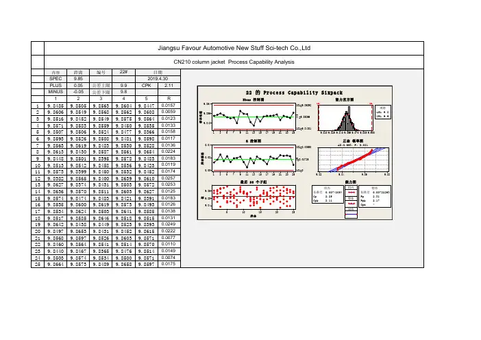
CN210s column jacket PPK-22#
- 格式:pdf
- 大小:63.13 KB
- 文档页数:1

Operating ManualKÖCO Compact Stud Welding EquipmentELOTOP8021002170220023002KÖCO Stud Welding GunsCLASSICSK 12K 22K 22-DK 24K 26This operating manual has the part-no. 399-0212-000Declaration of Conformity ECProducer:Köster & Co. GmbHSpreeler Weg 32EnnepetalD-58256Designation of Product: Stud welding equipment series ELOTOP 802 to 3002 withstud welding gun series CLASSIC SK 12 to K 26The above mentioned equipment complies with the requirements of the following directives:Directive 98/37/EC relating to machineryDirective 73/23/EEC amended by 93/68 relating to electrical equipment designed for use within certain voltage limitsDirective 89/336/EEC amended by 91/263/EEC, 92/31/EEC and 93/68/EEC relating to electromagnetic com-patibilityThe above mentioned products observes the following European Standards and therefore compliy with the above mentioned directives:EN 60 204-1 “Electrical equipment of machines“EN 60 974-1 “Safety requirements of arc welding equipment“EN 50 199 “Electromagnetic compatibility - Product standard for arc welding equipment“Köster & Co. GmbHSpreeler Weg 32D-58256 EnnepetalEnnepetal, 2002-04-02SignatureTable of ContentsOperating Manual KÖCO Compact Stud Welding Equipment ELOTOP 802 1002 1702 2002 3002 1 KÖCO Stud Welding Guns CLASSIC SK 12 K 22 K 22-D K 24 K 26 1 Declaration of Conformity EC 2 Table of Contents 3 1Introduction 5 1.1Information for the User 5 1.2Safety Instructions 51.2.1Personal Safety 51.2.2Operational Safety of the Equipment 61.2.3Safety When Working 6 2Drawn Arc Stud Welding 8 2.1Technical Data on ELOTOP Power Sources 9 2.2The Power Source 10 2.3The Welding Gun 10 2.4Technical Data on Stud Welding Guns CLASSIC 11 2.5Setting Guidelines for welding with ceramic ferrule or shielding gas 12 2.6Setting guidelines for short cycle stud welding without weld pool protection or with shielding gas 13 2.7Material requirements 13 3Working with the stud welding equipment 14 3.1Requirements before starting-up 14 3.2Starting-up of the welding gun 14 3.3Starting-up of the Power Source 16 3.4Selecting of settings 16 3.5Welding 17 3.6Weld Testing 17 3.7Maintenance of the Welding Power Source 19 3.8Maintenance of the Welding Gun 19 3.9Maintenance of Welding and Control Cables 19 3.10Shutting-Down 19 4Remedies for Malfunctions 20 4.1Error signals of the Power Source 20 4.2Other Malfunctions 21 5Pictures of the Power Sources ELOTOP 23 6Spare Parts for Welding Power Sources ELOTOP 29 7Pictures of Stud Welding Guns CLASSIC 318Spare Parts for Stud Welding Guns CLASSIC 35 8.1Spare parts list gun SK 12 35 8.2Spare parts list guns K 22, K 22-D, K 24, K 26 36 9Pictures of Cables 38 10Cable Spare Part List 39 11Schematic Circuit Diagrams 40 12Accessories 46 12.1Gun accessories for stud welding guns K 22 to K 26 46 12.2Gun accessories for Gun SK 12 59 13Literature 631 IntroductionDear User,With the KÖCO Stud Welding Equipment ELOTOP you have purchased an appliance of superior quality. It has been constructed according to latest technical principles and complies with all technical regulations and re-quirements in force at the time of delivery. To achieve trouble-free operation at all times we recommend that you observe the following instructions:Before starting-up carefully read through the complete manual and make sure that anyone on your staff handling or operating the appliance has also read and understood the instructions.The safety instructions must be followed at all times.Store this manual in a safe place, with easy access for anyone operating the appliance.Secure the machine against use by unauthorized persons.The appliance may only be operated by sufficiently qualified personnel.Have a trained electrician inspect the mains connection for correct fusing and earthing.if any malfunctions occur which you cannot remedy yourself, call our after-sales service.In case of accidents call for proper medical help, and if necessary, notify accident insurers and/or local trade supervision authorities.1.1 Information for the UserThe manual for your KÖCO stud welding equipment ELOTOP and the KÖCO stud welding guns CLASSIC con-tains any necessary instruction to the equipment, for safe carrying-out of stud welding operations and their as-sessment. All information supplied is given to the best of our knowledge, but without accepting any liability on our part. In particular, we cannot accept any responsibility for welding suitability of workpieces, nor for the suit-ability of the stud welding process for certain applications. In all of these cases reponsibility for welding results rests with the user.We shall be glad to assist you with any questions you may have concerning particular applications or remedies for malfunctions. Any suggestions on your part towards improving this operating manual will also be welcome.Instructions1.2 SafetyThe KÖCO stud welding equipment ELOTOP and the KÖCO stud welding gun CLASSIC is designed for use in drawn-arc stud welding only. It must not be used for any other purpose, with the exception of manual electrode welding, and then only if the appliance is equipped for this purpose. In particular, welding under water is strictly prohibited, nor is it permissible under any circumstances to use the appliance for thawing up frozen water pipes.1.2.1 PersonalSafetyKÖCO stud welding equipment ELOTOP and the KÖCO stud welding guns CLASSIC are approved for welding under increased electrically hazardous conditions, according to DIN EN 60974-1. For his own safety, the opera-tor must wear protective clothing during welding, which includes the following:Dry, insulating shoesNon-flammable, close-fitting working clothes (5) (leather apron)Leather glovesSafety goggles with an adequate degree of protectionA special helmet with neck protection while engaged in overhead weldingNo metallic jewellery (rings, chains, etc.) nor watches may be worn during welding.During the welding process, persons wearing heart pace-makers must be kept at a safe distance from the appliance and the welding cables, because the strong magnetic fields could endanger their lives.In addition to the above, all normal accident prevention regulations must be observed.1.2.2 Operational Safety of the EquipmentFor the mains connection only a suitable mains plug or a fixed mains connection may be used. The installation of a fixed mains connection (including fitting of the mains plug) may only be carried out by a trained electrician.All cable insulation must be in perfect condition. Cables with defective insulation must be replaced im-mediately. Welding cables may carry high currents. At points subject to bending, for example where the ca-ble enters the handle of the welding gun, there is always a risk of the cross-section being gradually reduced due to breakage of individual wires. When subjected to a high pulsed current, a cable thus weakened may suddenly arc over and burn out. This means a risk of burns to the operator, and of inflammable objects nearby being ignited.All parts of the housing must be firmly attached. Operation with an open housing is not permissible, because then there is no protection against touching live parts, and effective ventilation is also prevented.The insulating wheels (casters) must be in perfect condition. If these casters are removed in order to install the equipment in a fixed position, alternative insulation must be provided between the workpiece and the housing. If an electric connection between the workpiece and the housing exists during welding, this may, in case of malfunction, destroy the protective earth-line of the equipment.The interior of the appliance must be kept clean. Especially when working in dusty surroundings, dust will collect on parts of the equipment. Therefore, the housing should be opened at regular intervals (only af-ter first disconnecting the mains plug) and the dust blown out. This is vital in the case of metallic dust, be-cause it can lead to short circuits and thus cause damage to the components. Do not aim the jet of air at any pc boards, but remove the dust from these with a vacuum cleaner.Sufficient cooling. The cooling air is taken in at the bottom and blown out at the rear side. Provide suffi-cient facilities of air ventilation. Do not cover the ventilation openings.The welding gun must be in perfect condition. All connections in the welding circuit must be tight. Make sure that the chuck is firmly seated on the adapter screw and that the stud is firmly seated in the chuck.Otherwise contact scorching may result. Do not operate the gun without rear cap. For adequate protection against welding splashes and smoke the bellows protection must always seal perfectly.Electrical safety: Before opening the appliance always disconnect it from power supply by pulling out the mains plug, making sure that it is not possible to switch it on unintentionally. Prevent moisture or foreign substances from entering the power source. If this happens, the appliance must immediately be discon-nected from the mains power supply. The appliance should also be inspected by a qualified specialist at regular intervals, especially following any malfunction. Make sure that all markings remain visible!1.2.3 Safety When WorkingDo not operate the equipment in areas of fire or explosion danger. Remove all inflammable objects from the surroundings!Keep in mind that welding splashes are likely to ignite inflammable objects, for example cleaning rags soaked with oil, grease or solvent, or packing materials, even at several metres’ distance!In case of doubt check with the security officer in charge and obtain his release before commencing work! Make sure that the operating site has sufficient ventilation!Do not weld without air extraction on any workpieces which may release substances dangerous to health, such as coating materials, zinc, nickel, chromium or cadmium!Do not carry out welding on hollow objects which contain, or have contained, inflammable liquids or gases, or which are under pressure, or inside which a dangerous level of pressure can be generated by welding heat!The heat generated by welding may lead to the release of gases or vapours which are dangerous to health or even explosive. Specialized knowledge is required for this kind of work. Do not carry out such operations unless you possess the necessary knowledge!Keep at a safe distance from any equipment which might be affected by magnetic fields, such as EDP in-stallations (computers), cards with magnetic strips, or timepieces (wrist-watches)Do not weld on the same workpiece (welding potential) simultaneously with other types of welding ma-chines, especially those working with different poles or frequency (alternating current), or welding equipment with high voltage ignition, because this can adversely affect or damage the control unit of the stud welding appliance.Ensure that a flawless safe welding circuit is generated. The earthing cables should be firmly clamped onto the workpiece. If this is not possible or not desirable, make sure that there are no parts in contact with the welding circuit which can be damaged or destroyed by the welding current, such as crane hooks, rolling bearings, clamps with layers of partly insulating material, screws or rivets. Especially dangerous is the de-struction of protective conductors in other electric appliances when they come into contact with the welding current.Whenever the appliance must be placed on sloping ground, secure it against tipping over or rolling downhill. For transporting the equipment, use only the parts specially provided for this purpose. When lifting it by crane, this must be done by using the crane lug. Before attaching it, make sure that the nuts are properly tightened. The handles of the appliance are not designed for transporting it by crane.2 Drawn Arc Stud WeldingDrawn-arc stud welding is used for the welding of metallic parts, generally of cylindrical shape, onto metallic workpieces. For this purpose, a DC power source and a mobile device, the welding gun, are required. Depend-ing on the type of welding-pool protection and welding time range used, the appropriate process may be stud welding with a ceramic ferrule, stud welding with with shielding gas, or short-cycle stud welding, either with or without shielding gas.The welding procedure is illustrated below: Figure 1: Drawn-arc stud welding procedure Explanation:A: Stud welding with ceramic ferruleF: Ceramic ferruleP: ProtrusionL: LiftA 1:The stud contacts the workpiece.A 2: The stud is lifted off under current flow and thus the arc ignited.A 3: The drawn arc melts the tip of the stud and the portion of the workpiece di-rectly beneath it. At the end of welding time the stud is pressed (plunged) into the molten part of the workpiece.A 4: The melt solidifies, resulting in a firm cross-sectional weld. The ceramic ferrule is then removed.B: Stud welding with shielding gas. (B 1 equivalent to A 1)S: Shielding gas supplyC: Short-cycle stud welding with or without shielding gas (C 1 equivalent to A 1)T. Supporting tube2.1 Technical Data on ELOTOP Power SourcesTechnical data 802 1002 1702 2002 3002Stud welding with ceramic ferruleWeldable stud range Ø (mm)3 - 12 3 - 14 3 Ð 20 3 - 22 6 - 25 Short-cycle stud weldingWeldable stud range Ø (mm)3 - 8 3 - 10 3 - 12 3 - 12 6 - 12 Stud welding with shielding gas Weld-able stud range Ø (mm)3 - 10 3 - 12 3 - 16 3 - 16 3 - 16 Max. Current (A) 800 1100 1800 2300 3500 Stepless current adjustment range, (A) 50 - 750 150 - 1000150 - 1600 300 - 2000 300 - 2600 Stepless time adjustment range (ms) 20 - 600 20 - 1000 20 - 1500 20 - 1500 20 - 2000Max. weld rate in studs/min. for ... stud Ø (mm) 32/ 33/ 1249/ 34/ 1450/ 32/ 2052/ 34/ 2250/ 66/ 25Input voltage, three-phase 50/60 Hz (V) 230/400 230/400 230/400 230/400 230/400 Alternative input voltages (V) Option Option Option Option OptionMains plug 400 V (A) 32 32 63 63 /125 1) 125 Mains cable 4-pole, 400 V (m/mm²) 5/4 5/4 5/10 5/16 5/16 Max. extension cable permissible tomains connection (400 V mains, cross-section identical to mains extensioncable) 2)50 40 40 30 30 Time-lag fuse for 230/400 V (A) 35/25 50/35 100/63 160/80 200/125Input performance at ...% ED (kVA) 1,4/3,2/10055/38/7 2,5/7/10073/43/122,25/9/100121/59/172,5/7/100156/93/258/13/100187/145/52Max. welding cable length under given current (A) with given cross-section 2)600 / 25 mat 70 mm²800 / 30 mat 70 mm²1200 / 40m at 70mm²1600 / 40 mat 95 mm²2000 / 50 mat 120 mm²Input voltage tolerance (%) -15/+6 -15/+6 -15/+6 -15/+6 -15/+6 Class of protection IP 23 IP 23 IP 23 IP 23 IP 23 Cooling F F F F 3) F3)Housing dimensions (L x W x H) mm 530x305x350 600x325x370700x415x460805x430x530960x610x625Weight (app. kg) 50 87 160 185 355 Operating under increased electrical hazard permissible, CE-labelling according to EN 60974-11) According to customer’s choice2) The permissible max. lengths of extensions to mains and welding cables may be extended for welding under lower currents than the current given. For mains voltages below 400 V, the mains cable cross-section must be increased proportionately (i.e. by the factor 1.73 for a 230 V input). In case of low current input it may not be possible to use maximum lengths for both mains and welding cable extensions.3) Noise level: 72 db(A)2.2 The Power SourceThe power source consists of a 3-phase transformer, a fully controlled thyristor bridge with constant current control, a choke connected in series, and an electronic control. The standard setting of the appliance is for an input of 400 V (3-phase). Setting for 230 V (3-phase) input can be effected through adjusting the links on the terminal board of the main transformer. Power sources for alternative voltages are also available. How to adjust the appliance to other input voltages is shown on a sticker attached to the terminal board and illustrated in the wiring diagram. All ELOTOP power source models can be supplied with alternative nominal voltages.Nominal output of the equipment can still be reached with an undervoltage of up to minus 10%. However, de-pending on circumstances, it may become necessary to shorten the extension cables, to prevent exceeding the capacity of the constant current control. If the input voltage drops below minus 15%, the appliance can no longer be operated.Because the load-voltage may be considerably lower than the no-load-voltage, especially in case of a weak power supply, in a case of doubt a voltage measuring should be carried out during the welding procedure. When welding with 400 V input, the primary current is approximately 10% of the welding current.Example: welding current 1600 A = primary current abt. 160 A.The mains must be capable of supplying this primary current with minimum fluctuation to voltage. Since the flow of current is only short (max. 1,5 sec) mains fuses of considerably reduced rating may be used, provided, of course, that they operate with sufficient time-lag. Quick acting fuses (including safety cut-out switches) may prevent operation of the appliance.Fuses with lower ratings than indicated under table 2.1 may be used if less than the full capacity of the power source is required in operation.If a mains plug with a lower rating is chosen, for example 63 A instead of 125 A, only mains fuses with a maxi-mum rating equal to that of the mains plug may be used, in this case 63 A. The mains connection cable must have a cross-section sufficiently large to ensure that undervoltage is kept within the margin of tolerance. All cable cross-sections and mains fuses must comply with technical regulations and requirements of electricity suppliers.An overvoltage of 15% should not be exceeded, since otherwise iron losses in the transformer will cause over-heating.2.3 The Welding GunIn drawn-arc stud welding the welding gun is used to generate the arc between stud and workpiece, and to unite the two welding pools at the end of welding time.There is a choice of two different concepts. The guns K 22 to K 26 have an automatic length adjustment facility, i.e. maintenance of the pre-selected lift is guaranteed independent of protrusion, variation of stud lengths within normal tolerance and minor deviations from the vertical position of studs in relation to the workpiece. However in case of very short welding cycles (below 100 ms) the necessary coupling does not react fast enough. Therefore we recommend the SK 12 gun without length adjustment specially for short-cycle stud welding. It should be used for studs with only very minor variations in length and when constant conditions for the positioning of the welding gun apply.In stud welding, lift and protrusion are important parameters. In most cases they can be selected to fit stud di-ameters, according to figure 2. The position of the weld or the kind of surface on the workpiece may necessitate some adjustments. In such cases, optimal settings should be obtained through test welds.The length of lift is the vital factor in determining the form of metal melting at the tip of the stud. In case of major deviation from optimal values, cavities may form in the welding pool. Moreover, if the lift is too small, an in-crease in the number of droplet short circuits will destabilize the welding process. The protrusion (see figure 4) will determine the form of the welding collar around the welded stud. In some cases, especially when welding onto a vertical wall, settings other than those listed may be selected. If the plunge is too shallow, this will lead topores and undercuts in the weld zone. If it is too deep, the welding pool will splash out to the side or upwards with the risk of blockage to the downward movement of the stud. The setting of protrusion is described in sec-tion 3.2.8.For studs above 14 mm the plunging movement should be damped. This is achieved through adjustable plunge damping. (For settings refer to Section 3.2.11).2.4 Technical Data on Stud Welding Guns CLASSICTechnical Data SK 12 K 22 K 22-D K 24 K 26Stud welding with ceramic ferruleWeldable stud range Ø (mm) 1) 4 - 12 4 - 14 4 – 19 13 - 22 13 - 25Short cycle stud weldingWeldable stud range Ø (mm) 3 - 12 6 - 12 -- -- Stud welding with shielding gasWeldable stud range Ø (mm) 3 - 12 3 - 16 -- -- Adjustable hydraulic damping of piston,for studs from abt. 14 mm Ø -Lifting ring system with length adjustment - Adjustment of stud length variations up to ... (mm) - 8 8 8 8Standard support by ... legs 2 2 2 2 3Lifting range from...to (mm) app. 1 - 3 1 - 4,5 1 - 4,52,5 - 6 2,5 - 6Input voltage of lifting coil (V=) 60 - 90 60 - 9075 - 90 75 -90 75 - 90 Welding cable (m/mm²) 5/35 2/50 2/50 2/95 2/120 Welding cable plug (mm²) 35 50/70 50/70 95 120Control cable plug 4-poleControl cable (m/mm²) 5/4x1,0 2/4x1,02/4x1,0 2/4x1,0 2/4x1,0 Length (excluding chuck) (mm) 200 175 175 250 300Body diam. app. (mm) 50 60 60 60 63Height (including handle) (mm) 150 165 165 220 240Weight (excluding connection cables) app. (kg) 0,8 1,3 1,3 1,4 2,6= Standard = optional − = not available1) For very high performance welding and large stud diameters we recommend a larger type of gun. In case of doubt please consult the maker or a sales representative for details.2.5 Setting Guidelines for welding with ceramic ferrule or shielding gasThe settings given in figure 2 have been tested for welds on clean metallic surfaces and standard type studs in downhand position. The decisive parameter is the actual diameter at the welding end of the stud, not the nominal diameter. Under different conditions (other welding position, or oily, scaly or primer-coated surfaces) the optimal settings must be determined by test welds. With difficult surfaces, it may be necessary to considera-bly increase lift and welding time, and to reduce the welding current. When welding in a horizontal position, it is recommended to select higher current, protrusion and plunging speed than the given settings, and at the same time shorter cycles and lift. Please note that at the lower end of the welding range of large appliances it may be necessary to select values higher than those listed in the chart. This is caused by the relatively long phase for building up the current, which means that for a considerable part of the welding cycle the peak current is not yetreached. This must be compensated by lengthening the welding cycle or selecting a highter current.Figure 2: Parameters for current, time, lift, protrusion and dampingThe plunge speed is adjusted by setting the damping of the piston. In case of studs with less than app. 10 mm Ø guns without damper (SK 12 or K 22) should be used, or the damper should be removed (refer to 3.2.11). If the correct damper setting is selected, only very few splashes will occur during plunge, and an even welding collar without undercuts will be formed.Before starting a series of welds, test welds according to DIN EN ISO 14555 should be carried out. For details refer to DVS-leaflet 0902.Explanation: P: protrusion, L: lift, Ø: stud di-ameter, I: current, t: time, v: plunging speed2.6 Setting guidelines for short cycle stud welding without weld poolprotection or with shielding gasShort cycle stud welding is used where it is desirable to keep the penetration on thin workpieces as shallow as possible, normally with studs ranging from M 3 to M 12 (FD type flanged studs according to DIN EN ISO 13918). If the outward appearance of welding collars is not important, protection of the welding pool can be omitted. However, in that case a current of at least app. 100 x the nominal diameter of the stud should be selected, i.e. in case of a M 8 stud the power source should have a minimum output of 800 A. Basically, the current should be as high and the time as short as possible.If the time is extended beyond a certain measure to allow for a weak power source, this will result in uneven, porous welding collars.Welding with shielding gas will result in flawless welding collars and few pores in the welding zone. Acceptable results can also be obtained with longer welding times and lower currents. For welding steel or stainless steel the use of a gas mixture M 21 (82% Ar, 18% CO2) according to EN 439 is recommended.In short cycle stud welding the settings depend not only on the stud diameter, but also on the thickness of the workpiece and the caliber of the gun. In the DVS-leaflet 0904 a table of setting guidelines is given. In principle, one should always start by selecting the highest current and the shortest welding time possible on the power source, and then adjust the settings after some test welds.2.7 MaterialrequirementsIn principle, all materials suitable for fusion welding are also suitable for drawn arc stud welding. However, for some sensitive varieties of steel there is a certain risk that they may harden and become brittle by the quick heating and cooling processes involved. If two different materials are welded together (for example carbon steel with stainless steel) a new alloy will result which may be resistant to further shaping. Because of the short weld-ing time, clean surfaces are essential for good welding results. For further details refer to literature (refer to section 13). So-called “free cutting” steels are generally not suitable for stud welding. In practice, the following combinations have proved satisfactory:Chart 1: Recommended material combinations for drawn arc stud weldingParent metalsStud material Non-alloy steels up to app. 0,24% C,for example S235, S355, 16Mo3 Stainless Austenite steels, such as 1.4301, 1.4401, 1.4541, 1.4571Non-alloy steels up to app. 0,18% C, e.g. S235, 4.8, 16Mo3 Suitable, including for force transfer For stud welding with ceramic ferruleonly limited suitablity for force transferFor short cycle stud welding wellsuitedStainless Austenite steels, such as 1.4301, 1.4401, 1.4541, 1.4571 For stud welding with ceramic ferruleonly limited suitability for force trans-ferwell suited for up to 10 mm Ø withshielding gasFor short cycle stud welding wellsuitedSuitable, including for force transfer 1)1) In fully austenite steels attention should be paid to the relatively high risk of hot cracks.In addition to the material combinations listed above, heat- and scale-resistant studs may also be welded, in special cases also aluminium studs. For material combinations not previously tested, welding suitability must be determined through appropriate test welds. (For further details, refer to section 13, literature).3 Working with the stud welding equipment3.1 Requirements before starting-up1. Ensure adequate power supply, according to instructions under section2.2.2. The power connection must be earthed according to regulations.3. The housing of the welding power source must not have any electrical contact with the workpiece. Makesure that the insulating wheels (casters) are in perfect condition!4. Make sure that the welding power souce is standing firm in a vibration-free, dry area!5. Make sure that there is sufficient cooling! The circulation of air must not be restricted in any way.6. Operating the equipment in a fire or explosion danger area is prohibited. In case of doubt obtain a releasefor the welding operation from the security officer in charge.7. Keep a safe distance from any objects which may be affected by strong magnetic fields, such as EDP instal-lations! Make sure that persons wearing a heart pace-maker do not come close to the welding cables!8. Shielding gas bottles must be secured against falling over.3.2 Starting-up of the welding gun1. Screw the desired chuck on to the adapter screw of the gun, slightly tightening it with a wrench .2. Using the counter-sink screws and washers supplied, attach the two legs to the desired footplate. Initially,do not tighten the screws.3. Insert the desired ceramic ferrule grip (when welding with a ceramic ferrule) or the supporting tube (in caseof short cycle welding or welding with shielding gas) into the footpiece, pushing it to the stop. Secure the ce-ramic ferrule grip or the supporting tube with the screws at the sides of the footplate.4. Insert a suitable stud into the chuck, pushing it up to the stop.5. Slide the footplate with the legs in the damping guides of the gun, so that the tip of the stud reaches ap-proximately the same height as the ceramic ferrule grip or the supporting tube.6. Move the footpiece until the stud is centrally seated in the bore of the ceramic ferrule grip or the supportingtube (see figure 3).Then tighten the counter-sink screws of the footplate. Figure 3: Centering of the footplate Explanation: A: Correct center-ing of the footplateB: Inaccurate cen-tering of the foot-plate will cause blockage of the plunging move-ment of the stud.。
