a Universal Development Environment for Formal Methods
- 格式:pdf
- 大小:182.37 KB
- 文档页数:20

B1U6-U8课后段落翻译中英对照版B1 U6Part IGap year(间隔年)refers to a period of time---not necessarily a year--- in which students take timeoff and do something other than schooling, such as travel or work. The year out is most commonlytaken after high school and before going to university. During this time, a student might travel,engage in volunteer work or undertake (承担)a working holiday abroad.A new trend is toparticipate in international education programs that combine language study, home stays, culturalexchange, community service, and independent study. The practice of taking a year out developedin the United Kingdom in the 1960s. It has grown very popular among students in the UK, Australia, New Zealand, and Canada. In the United States however, the practice of taking a year off remains the exception (例外). But in recent years, taking a year out has become slightly more common for Americans. Some 40,000 American students participated in 2013 in gap year programs, an increase of almost 20% since 2006. Universities such as Princeton University, Harvard University,Massachusetts Institute of Technology have formal policies allowing students to defer (延期)admission.间隔年指的是学生休假不去上学而去旅游或工作等的一段时间,但不一定是一年。

Model-Based Development ofEmbedded SystemsFranz Huber, Jan Philipps, Oscar SlotoschValidas AGwww.validas.de{huber,philipps,slotosch}@validas.deAbstractWe describe concepts and processes for model-based development of embedded control systems. Tool support for such an approach is provided by the award-winning AutoFocus/Quest tool set jointly developed by TU München and Validas AG. We outline real-time extensions for the mod-eling languages and show how to use time information for testing. A small case study demon-strates these extensions.IntroductionSoftware development approaches that rely on modeling a system before performing the actual implementation work have a long history in computing. Among the first ones were data(base) modeling approaches using the Entity/Relationship model and similar other techniques. During further development, modeling techniques became increasingly complete, covering not only data aspects, but also structural/topological and behavioral aspects of systems. Typical representatives of such full-scale modeling approaches are structured methods, such as Structured Analysis & Design, or object-oriented methods like the UML [4].Models created in such a modeling language can serve different purposes. They can be regarded as a concise, much more formal version of otherwise informally given system requirements. In this view, they serve as a precise guideline for the developers that perform the actual implemen-tation work, and can furthermore be used as a basis for testing the conformance of the imple-mentation with the requirements.If a modeling language is rich enough to allow the creation of complete models (models that en-compass all aspects of a system on an abstract, implementation-independent level), another pur-pose of such models is obvious: The created models can not only be used to precisely capture the requirements upon the system, but to describe the system in detail, reaching up to a complete description of all aspects of the system. From such a complete description, it is basically possible(although not always feasible or desired in practice) to generate a complete system implementa-tion automatically. An important advantage of such a model-based approach is (programming) language independence: Modeling languages are usually driven by the application domain that they are used in and provide application-oriented abstractions to describe systems (components, data entities, states, state transitions, etc.). In contrast, typical programming languages such as Ada or C are general-purpose languages, providing language elements that reflect the underlying machine model of sequential execution of statements. Using code generation techniques to create implementations, such complete models as described previously can be transformed into imple-mentations in arbitrary programming languages.Models are abstractions of a system and are thus particularly less “cluttered” than an implemen-tation, for instance, in C. Therefore, it is much more promising for models than for implementa-tions to apply validation techniques, such as—covering different levels of formality—prototyping and simulation [7], test case/test sequence generation [12], or model checking [9]. If the elements of a modeling language have been chosen carefully enough to keep the modeling language sim-ple, yet complete, it is feasible to provide a sufficiently streamlined formal semantics that even allows the application of rigid formal validation/verification techniques [5].Subsequently, we introduce such a simple, yet powerful modeling language—the AutoFocus modeling language & framework [8]—and outline some of the validation techniques that can be applied to AutoFocus models. The AutoFocus modeling language has been under development since 1995, specially aimed at the development of embedded systems, and shares some concepts with UML/RT.Model-based Development ConceptsA modeling language—quite similar to a programming language—comprises a set of concepts that are used to describe systems. In case of programming languages, these concepts are typically statements, blocks, procedures, functions, and many more. For the AutoFocus modeling language and toolset, these concepts are based on the idea of a system being made up of a network of communicating components. Usually, the concepts that describe a modeling language are defined in a so-called meta-model (i.e., a model that describes how models in that modeling language can be constructed). A simplified representation of the AutoFocus meta-model is shown in Fig. 1, using the UML class diagram notation as the meta-language.AutoFocus Modeling ConceptsThe core modeling concepts of AutoFocus, i.e., the core elements in the its meta-model are as follows:Components. They are the main building blocks for systems. Components encapsulate data, in-ternal structure, and behavior. Components can communicate with their environment via well-defined interfaces. Components are concurrent: Each one of them runs sequentially; however, in a set of components, each component’s run is independent of the other components’ runs. Com-ponents can be hierarchically structured, i.e., consist of a set of communicating sub-components. Data types. They define the data structures used by components. Data types are constructed from a set of basic types (such as integer or float) and a set of constructors, e.g., for record and variant types.Data. Data elements are encapsulated by a component and provide a means to store persistent state information inside a component. Data elements can be regarded as typed state variables. Ports. They are a component’s means of communicating with its environment. Components read data on input ports and send data on output ports. Ports are named and typed, allowing only spe-cific kinds of values to be sent/received on them.Channels. They connect component ports. Channels are unidirectional, named, and typed, and they define the communication structure (topology) of a system.Control States and Transitions. These elements define the control state space and the flow of control inside a component. Each transition connects two distinct controls states (or one control state with itself, in case of a loop transition) and carries a set of four annotations determining its firing conditions (its “enabledness”):•pre-conditions and post-conditions, which are predicates over the data elements of the component to be fulfilled before and after the transition, respectively, and •input and output patterns, determining which values must be available on the compo-nent’s input ports to fire the transition and which values are then written to the output ports.Fig. 1. Basic Modeling Concepts of A UTO F OCUS: The Meta-ModelThese concepts are sufficient to describe a large class of systems. Developers create the model of an actual system using these concepts; technically speaking (e.g., with a modeling tool for this language in mind), an actual system model is an instance of this meta-model. The complete meta-model, together with a set of additional conditions relating to consistency and completeness of models, describes the set of all possible, well-formed models that can be created.Views and Description TechniquesDevelopers do not create and manipulate models as a whole, but by picking only specific parts of them, which are of interest during particular development activities. These parts, usually closelyrelated with each other, make up the views of the system. For instance, the structural view in A UTO F OCUS considers only elements from the meta-model describing the interface of compo-nents and their interconnection.To manipulate elements of these views we must represent them visually. In A UTO F OCUS we use mainly graphical notations for that purpose; these notations are introduced in more detail by our application example. The notations do not represent self-contained documents; instead they are a mere visualization of a clipping from the complete model. Fig. 2 shows an example for this rela-tionship between a set of related elements from the meta-model (inside the shaded area) and their visual, diagrammatic representation. In this example, structural aspects of the model are covered, and the notation used to visually represent them is called System Structure Diagrams (SSDs for short).b l e O pFig. 2. Structural Parts of the Meta-Model and the Notation representing them Model-based Development ProcessOne of the main difficulties in software engineering is that the requirements of the customer are prone to change while software is being developed. In standard waterfall development process models, which are still regularly used in industry, requirements analysis and testing are located at opposite ends of the development process. Evolutionary development processes, on the other hand, try to alleviate this problem by building the software system incrementally. Requirements are not fixed in an early development phase, but instead converge during several incremental cy-cles with customer interaction after completion of each increment.In this section, we first give a short overview over incremental development processes, and then describe how a process based on executable models is supported by modern CASE tools, such as AutoFocus. Finally, we explain the step from executable models to final code.Incremental DevelopmentBoehm’s spiral model [3] is the most famous incremental process model, although it is more a meta-model of a process than a proper development process model. More helpful for real soft-ware development are the Cleanroom Reference Model (CRM) [11], and so-called agile ap-proaches, most notably Extreme Programming (XP) [2], which is based on classical object-oriented programming languages.We believe that modeling languages fit the demands of an incremental process better than pro-gramming languages: Their higher level of abstraction leads to higher productivity of the devel-opers; their suggestive notations ease interaction with the customer and other developers. Never-theless, models are executable, which results in immediate feedback for the designer and the customer.The idea of incremental model-based development amounts to specifying the model of the system as precisely as possible, so that the model is always executable. In order to handle the complexity of the system, in a first step only a small part of the core functionality of the system is described. The specification is then (together with the customer) validated and verified by simulation, in-spection and reviews, and by formal verification and analysis techniques. Later steps refine this model: More components are added to the model in order to add functionality; the behavioral specifications of the components are elaborated to handle exceptional cases; additional inputs and outputs are added, for instance to ease maintenance of the final product.Besides the modeling activities themselves, the process consists of the following activities:•Simulation: Model executability is the basis of the main validation technique employed in our incremental process [7]. Together with the customer, exemplary system runs are produced that demonstrate the model essentially operates according to the customer’s re-quirements.Simulation is not restricted to interactive step-by-step executions. Using advanced sym-bolic execution techniques based on constraint-logic-programming, it is possible to auto-matically derive simulation runs from abstract test case specifications; a test case specifi-cation typically demands that the model is brought into a certain state (functional tests) or that every transition is executed at least once (structural tests).•Analysis: While simulation is helpful to determine that the system indeed fulfils its re-quirements, there are some questions related to quality assurance that cannot be answered by simulation alone, since simulation gives answers only about single system runs, not about all possible system runs (mathematically, simulation shows existential properties, not universal ones). Some typical questions are whether the model is deterministic (i.e., for each input from the system environment there is at most one possible output specified) and complete (i.e., for each input from the system environment there is at least one possi-ble output specified). The AutoFocus toolset includes analysis tools that help to answer such questions. It also includes verification tools such as model checkers [9], which are used for mathematical proofs of critical system properties. Since such proofs are very ex-pensive (in terms of time, effort and required expertise of the tool user), the use of verifi-cation tools must be carefully judged against the economic risk of system malfunctions.•Refactoring: An obvious problem with any incremental system development process is that the resulting system specification may be cluttered and hard to understand, as itsstructure is determined partly by the order in which the increments occurred. Extreme programming makes use of elaborated refactoring [6] patterns to clean up the system after each increment so that it is both easier to understand and more amenable to further incre-ments. Similar techniques can be used for executable models; however, this is still an ac-tive area of research.To summarize, we advocate a development process that consists of several iterations where at the end of each loop, instead of hand-written code an executable system model is presented to the customer. This approach is similar to Extreme Programming, but focuses on a more abstract modeling of the system rather than its implementation. In contrast with Extreme Programming, however, production of the final code is deferred until the end of the development process. From Models to ProductsOnce the model is considered to be sufficiently correct and detailed, it is used as the basis for the production of the target code. For the target code, too, quality assurance must be performed. As the resulting code is likely not amenable to automatic analysis, the core activity here is testing (see, e.g., [10]). Essentially, there are two approaches:•The target code is produced by hand. This is a typical situation for customer/supplier re-lationships, where the model serves as the software specification of the final product. In this case, the code produced by the supplier must be tested to ensure its conformity with the model. It is possible to automatically derive test sequences for the implementation from simulation runs, in particular from the runs produced by symbolic execution as mentioned above.•The target code is produced by an automatic code generator. While in principle it is pos-sible to mathematically verify code generators, in practice there is still some risk (albeit a very small one) that the code generator produces incorrect code. Thus, even for automati-cally generated code it is prudent to test the code. For avionics systems, rigorous testing is even required: Standards such as DO-178B require, among other points, tests with clear code coverage criteria (MC/DC); it is not sufficient to have coverage only on the models. In both cases, however, additional tests must be performed to ensure that the model is not based on incorrect assumptions about the interaction with the environment, which could lead to timing problems and race conditions. Such tests can be performed by Hardware-in-the-loop approaches. Example: A Digital WatchAs an example of the description techniques of AutoFocus, this section presents parts of a model for a digital watch. The watch has three buttons (T1, T2, T3) that are used to change the display mode (date, time, stopwatch) and to set the current time and date after a battery change. Fig. 3 shows the top-level structure diagram of the watch model.The data types of the channels are defined using Data Type Definitions (DTDs) as follows: data Signal = Present;data Segments = Date(Int,Int,Int,Int,Int,Int)| Time(Int,Int,Int,Int,Int,Int)| Stop(Int,Int,Int,Int,Int,Int);Fig. 3. Top-Level View of the WatchDeeper in the modeling hierarchy, the watch component contains a time component that com-putes the time of day from internally derived signals (hs, zs) that hold the time of day in 1/100s and 1/10s; they are derived from an internal counter. There are other components to keep track of the current date and to model the stopwatch function.The time component (see Fig. 4) is quite complex, because it is also responsible for the adjust-ment of the time by the user. It has separate components to compute the segment digits for the display (Sec1, Sec10, Min1, Min10 and H12); depending on the current display mode they either display the relevant part of the current time, or the current time setting when the watch owner changes the time.Fig. 4. Component Network inside the Time Component of the WatchNote that in the diagram there are two kinds of channel connectors: Delayed channels (marked with a circle) and immediate channels (marked with a diamond). Messages sent through an im-mediate channel are visible to the receiver in the same reaction; messages sent through a delayed channel are visible in the following reaction. There are some subtle methodical issues involved intheir use. Generally, immediate channels should be used for the data flow within an embedded controller. Without immediate channels it would not be possible to switch from 23:59:59 to 00:00:00 within one model reaction, because the overflow-values would be present only in the next time step. On the other hand, for mathematical reasons every communication cycle in the system must contain at least one delayed channel.Fig. 5 shows the behavior of the component Setting as an example for state transition diagram. It describes the way to set the time using the signals T1, T2, T3 and the current mode that is com-puted by another component of the model (the mode signal is also computed from the three but-tons, but it is handled separately for reasons of modularity). For example, incrementing the min-utes display is modeled with the transition T2?P; T3?; IncM1!Present which connects the state Minute1 to itself. The semantics of this transition is as follows: When button T3 is not pressed, but button T2 is, then send the signal Present to the minute segment component.Fig. 5. State Transition Diagram of the Setting ComponentIn addition to input and output statements transitions can be annotated with preconditions (which are predicates over local variables and values read from input channels) and actions (which are assignments to local variables). Together with the DTD specifications, this allow models that are completely independent from the target programming language. This is important for reusing the models for other targets (for example with a different processor and a different instruction set). While the model itself is not very ambitious, its implementation is, since the resources of the watch are severely limited (4bit processor, 2KB of memory). The model is indeed the basis of a watch implementation with an industrial partner, but we did not yet implement a code generator for the assembly language used in the project. Given the rigorous semantics of AutoFocus, which is very close to the description techniques, and the limited size of the watch model, it is still man-ageable to translate the model into assembly language by hand.The code that results from the watch model is not used stand-alone; it is linked with a number of arithmetic and I/O libraries.Extensions for Real-TimeWith the description techniques presented so far, models describe the functionality of the system under development in terms of input/output reactions. For the final implementation, in addition tothe functionality, timing requirements must be considered. They relate system executions with the physical time of the system’s environment. Typical timing requirements are stated as separa-tion requirements (two inputs or outputs must be separated by at least a certain duration), or as proximity requirements (two inputs or outputs must be separated by at most a certain duration). Timing requirements fulfill two purposes: They impose demands on the maximal execution time for an input/output reaction of the system (and thus on the performance of the target hardware), and they state assumptions on the duration of activities of the controlled hardware.Timing requirements can be concisely specified by annotated Message Sequence Charts. Fig. 6 shows a simple timing requirements for the watch: It states that the watch, when switched to date mode by pressing button T3, displays the date for three seconds (rather, any number of display messages are sent to the hardware until exactly 3 seconds have passed) and then returns to time mode. This requirement is a combination of proximity and separation requirement. Further (quite trivial) requirements specify that a second (rather, 1/100s) of model time corresponds to a second of real time.Fig. 6. Timing Requirements in a Message Sequence Chart (MSC) Obviously, the relationship between model time and real time must be verified. Currently, this is done by hand-written test cases, which measure controller execution time and environment re-sponse times. A more automatic scheme will translate time-annotated MSCs like the one above into special time observer components. These components run in parallel to a standard hardware-in-the-loop setup (see Fig. 7) and give verdicts on the satisfaction of timing requirements for notFig. 7.ConclusionThis paper touches only some of the issues of model-based development. While the classical ar-eas of CASE tools (description techniques and code generators) are quite stable in our toolset, the validation and verification tools are still undergoing development and field studies with our part-ners and customers. In particular, the promising field of model-based test case generation is making rapid progress. In order to cover not only the later phases of system design, but also re-quirements analysis, the AutoFocus toolset has been connected to the requirements management tool DOORS [1].Acknowledgment. Peter Braun, Heiko Lötzbeyer, Alexander Pretschner and Dr. Bernhard Schätz, our colleagues from TU München, have contributed greatly to our understanding of model-based development and to the AutoFocus toolset itself.References1. B. Bajraktari: Modellbasiertes Requirements Tracing. Master thesis, TU München, 2001.2.K. Beck: Extreme Programming Explained: Embrace Change. Addison-Wesley, 1999.3. B.W. Boehm: A spiral model for software development and enhancement. Software Engi-neering Notes, 11(4), 1994.4.G. Booch, I. Jacobson, J. Rumbaugh: The Unified Modeling Language User Guide. Addison-Wesley, 1998.5.M. Broy, O. Slotosch: Enriching the Software Development Process by Formal Methods,Proceedings of FM-Trends 98, LNCS 1641.6.M. Fowler: Refactoring. Improving the Design of Existing Code. Addison-Wesley, 1999.7. F. Huber, S. Molterer, A. Rausch, B. Schätz, M. Sihling, O. Slotosch: Tool supported Speci-fication and Simulation of Distributed Systems, Proceedings of International Symposium on Software Engineering for Parallel and Distributed Systems, 1998.8. F. Huber, B. Schätz: Integrated Development of Embedded Systems with AutoFOCUS.Technical Report TUM-I0107, Fakultät für Informatik, TU München, 2001.9.J. Philipps, O. Slotosch: The Quest for Correct Systems: Model Checking of Diagrams andDatatypes, P roceedings of Asia Pacific Software Engineering Conference 1999, 449-458. 10.A. Pretschner, O. Slotosch, H. Lötzbeyer, E. Aiglstorfer, S. Kriebel: Model Based Testing forReal: The Inhouse Card Case Study in Proc. 6th Intl. Workshop on Formal Methods for In-dustrial Critical Systems (FMICS01), Paris, July 2001.11.S. Prowell, C. Trammell, R. Linger, J. Poore: Cleanroom Software Engineering. Addison-Wesley, 1999.12.G. Wimmel, A. Pretschner, O. Slotosch: Specification Based Test Sequence Generation withPropositional Logic, Journal on Software Testing Verification and Reliability (to appear).。
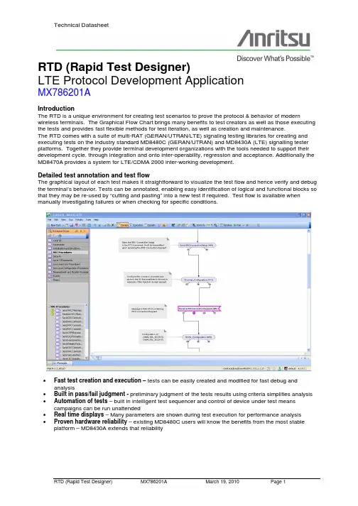
RTD (Rapid Test Designer)LTE Protocol Development ApplicationMX786201AIntroductionThe RTD is a unique environment for creating test scenarios to prove the protocol & behavior of modern wireless terminals. The Graphical Flow Chart brings many benefits to test creators as well as those executing the tests and provides fast flexible methods for test iteration, as well as creation and maintenance.The RTD comes with a suite of multi-RAT (GERAN/UTRAN/LTE) signaling testing libraries for creating and executing tests on the industry standard MD8480C (GERAN/UTRAN) and MD8430A (LTE) signalling tester platforms. Together they provide terminal development organizations with the tools needed to support their development cycle, through integration and onto inter-operability, regression and acceptance. Additionally the MD8470A provides a system for LTE/CDMA 2000 inter-working development.Detailed test annotation and test flowThe graphical layout of each test makes it straightforward to visualize the test flow and hence verify and debug the terminal’s behavior. Tests can be annotated, enabling easy identification of logical and functional blocks so that they may be re-used by “cutting and pasting” into a new test if required. Test flow is available when manually investigating failures or when checking for specific conditions.•Fast test creation and execution – tests can be easily created and modified for fast debug and analysis•Built in pass/fail judgment - preliminary judgment of the tests results using criteria simplifies analysis •Automation of tests – built in intelligent test sequencer and control of device under test means campaigns can be run unattended•Real time displays – Many parameters are shown during test execution for performance analysis •Proven hardware reliability – existing MD8480C users will know the benefits from the most stable platform – MD8430A extends that reliabilityVirtual Front panelThe RTD allows terminal development teams to create test scenarios with virtual front panel control. This provides a fast development, debug and proving environment without the need to recompile between iterations. In some cases it is possible to make changes to the parameterization while tests are running for examination of performance Automating the scenarios is also possible, so a single test can be used to check over a range of values without any human intervention. A real time measurement and monitoring application is available to see the effect of different loading and scheduling.Virtual ButtonsTests can include “soft-buttons” that allow a variety of functions and features for manual investigation of terminal performance. E.g. control of power levels during tests to be modified without re-running the tests.Example of virtual front panel with soft keysProcedure Library supportThere are two RTD Procedure Libraries available. LTE Low-level Configuration Library (Mar09) and a UTRAN/GERAN Layer 3 Procedure Library.These libraries are maintained with the 3GPP protocol specifications to provide a system that not only stays up to date with latest changes in the 3GPP process but also allows the user to upgrade existing test scenarios with a single command.LTE Procedure LibrariesAs LTE matures, the number of procedural blocks will increase and with updates occurring every 3 months, users can expect to keep up with 3GPP developments.UTRAN/GERAN Procedure Libraries3GPP progressionA very important feature of the RTD is the ability to update tests to the latest 3GPP Release. Entire archives of test scenarios can be updated automatically and for regression, backups of the original are saved.The Measurement and Monitor ApplicationRuntime information is available to the user in a number of ways. As well as protocol messages, the RTD provides an application that is used to measure throughput under a number of scenarios.Conditions can be changed while displaying the throughput of data in the graphical window.The Dynamic MSC provides a message sequence chart as the test progresses. This information is dynamically updated during runtime. The user can switch between Diagram and MSC view while the test is running without interrupting the logging of trace information. The trace is cleared when the test is rerun, but all the information from the test run will be stored in a Test Log Results file ready to view with the Protocol Analyzer.Test Results AnalysisThe RTD provides several ways to observe test results. A complete log of the messages is captured for viewing with the in-built protocol analyzer or may be exported to HTML for viewing on a web browser. Criteria EditorThe RTD is able to provide a preliminary judgment of the tests results using criteria that can be set by the test creator or modified later for custom judgment of the results. The criteria are determined by the flow of the tests with multiple loops possible to ensure that behavior is accurately recorded. At a high level: this is shown by a simple pass or fail .Further investigation reveals the cause of failure or abnormality.The screen below shows the criteria applied to the example test to determine incorrect behavior that can be traced back to the protocol messages in the resultant log.The test criteria may be modified by the user to prove specific functionality and applied to new and existing tests. For existing tests it has the added benefit that tests do not need to be re-run to analyze results against new criteria. Watermarking of tests and resultsWe encourage users to make copies of the tests and make changes for debug and other purpose, so all tests in the Anritsu test packages have a watermark that is broken if the test is modified. This provides confidence to the user that the tests and results from original tests have not been modified.SHOWS THE TEST AND RESULTS ARE WATERMARKEDWATERMARK BROKENAutomating testsRunning the Test Cases Using the AT/MMI Proxy for AutomationThe RTD provides proxy control of the AT command set to the terminal through the RTD Test Cases. It enables automated testing to be achieved through a serial porton the control PC. In order to use the AT commandsprovided within the test cases, the RTD AT/MMIcommand interface must be set to use the appropriateserial port connection and an appropriate proxy.xml file is applied to map the AT/MMI commands to matchthose supported by the terminal.Prompts on the screen can be suppressed whenautomation is used.Some points to note:•In general automated testing can be carried out via the use of the AT command set[3GPP TS27.007] •Full control of a terminal is only possible if the terminal vendor has made provision for anautomated testing interface•The combined AT/MMI proxy was developed as a flexible interface which can adapt to manydifferent types of terminals through the use of aconfiguration file ‘proxy.xml’•Where the vendor has not implemented a given AT command, for instance AT+CFUN which is used to power cycle the terminal between tests, itmay be possible to use the Keypad Controlcommand (AT+CKPD) which simulates the pressing of the terminal key pad via the AT commandinterface.Running the RTD within a test systemThe RTD may also be controlled using remote commands and integrated into a total test system. The RTD is compatible with a number of remote commands that allow Tests to be RUN, ANALYZED, etc.Campaign management within the tool The RTD includes campaign management. This provides the user with the ability to create test runs that can be run remotely.Tests can be repeated depending on rules set by the user. Results are generated in a tabular form and can be exported to form part of a formal report.A campaign may be used to run an entire suite of conformance tests, or inter-operability tests, or any other large grouping of tests.Test ResultsTest results may be summarized for reports and exported to external formats (such as XML or CSV). The Results Overview created within the tool may be used for regression purposes.LTE / UTRAN / GERAN Inter-workingThe RTD is able to control the MD8430A and MD8480C to simulate network behavior in LTE / UTRAN / GERAN Inter-working processes. This provides a compelling way for existing RTD users to upgrade using their existing tests and experience to develop even greater test coverage.LTE, UTRAN, and GERAN procedures can be used in a single test to create a combinedLTE/UTRAN/GERAN test.•MD8480C specifications•Up to 4 W-CDMA* cells and 2 TDMA** cells •Up to 2 physical RF channels•HSDPA up to 14.4MB: HSUPA up to 5.7MB •Enhancement to HSPA Evo•Part of RTD, PTS and PCT systems •MD8430A specifications•LTE for FDD and TDD covering 350 to 3000 MHz frequency band•100 MB (DL): 50 MB (UL)• 4 RF supports 2x2MIMO handover •Up to 6 Cells (2 communication, 4 neighbor)•Future proof – Cat 4 todayLTE/UTRAN/GERANterminalUTRAN/GERAN Simulation(3GPP Release 6 or before) MD8430AMD8480CRTDRTDCombinedLTE/UTRAN/GERANTestRTD Test PackagesIn order to provide the fastest route to market, RTD has an LTE Integration library available as an option for LTE development teams. The tests provide developers and integrators with 29 tests that will be available through 2010 and 2011.•Each test case is specified with a test case title, a brief description of the aim of the test case and the SS feature that they intend to demonstrate•The test cases are chosen to cover the majority of the LTE/SAE protocol areas•The test cases are designed to be usable as full-stack building blocks for customers to use to build system testsSupport and maintenance of the test packages includes upgrading and re-validating existing test cases to new platform versions of RTD as well as later 3GPP releases.We have support staff in the USA, UK and Japan to provide support to customers on issues they may have with their devices using tests in the test packages.Reference Test packagesRTD is delivered withreference test packages thatprovide a natural way todiscover the features andbenefits of the RTD. Coupledwith the operation manualsand the on-line help, thesetests are part of the overalltraining program.Acceptance Test packagesThere are a number of acceptance test packages available for RTD including The AT&T IOT Library Packages and T-Mobile USA UMTS Protocol Test Library PackagesRTD users now have the ability to purchase the Libraries outright or subscribe to them on an annual basis to suit their fiscal needs.Other 3rd party library packages may be available through partnerships with network operators.Watermarking of tests and resultsWe encourage users to make copies of the tests and make changes for debug and other purpose, so all tests in the Library have a watermark that is broken if the test is modified. This provides confidence to the user that the tests and results from original tests have not been modified.SHOWS THE TEST AND RESULTSARE WATERMARKEDWATERMARK BROKENOrdering informationRTD is configured to be very flexible and to allow existing Anritsu products to be updated and upgraded while still protecting investment in tests and equipment. Two examples of typical systems is shown below.LTE Protocol development systemConfigured for LTE R&D, Integration and regression with multi-cell capability L1/L2 and L3 Libraries & LTE Integration Test Package – uses MD8430A – STM hardware.ApplicationsThis configuration provides L1 / L2 and a L3 capability to allow LTE multi-cell test creation, editing and executing of the testsTechnologyThis configuration is for LTE FDDToolsThis configuration has full automation of tests and control of the DUT.ServicesSupport and maintenance for RTD is on an annual basis.Test PackagesThere are test packages for a number of different applications and technologies. This configuration provides an LTE package MX786201A – Rapid Test Designer (RTD) chassisMX786201A-028 – Layer 1 / 2 Statistics monitorMX786201A-038 - Low-level Configuration Library (LTE) MX786201A-039 - Layer 3 Procedure Library (LTE)MX786201A-040 – RTD CipheringMX786201A-045 - RTD test creation and editing capability MX786201A-052 – RTD dual-cell capability (run-time option) MX786201A-020 – Annual software support and maintenanceMX787201A - Framework chassisMX787201A-027 - Framework LTE coreMX787201A-028 - Framework LTE FDD option'MX787201A-SS100 – Annual support and maintenanceMX787401A - Signaling application tools chassisMX787401A-011 - Protocol Analyzer(RTD)MX787401A-012 - Remote controlMX787401A-013 - Terminal controlMX787401A-014 - Signaling Application Tool for TestSequencingMX787401A-SS100 – Annual support and maintenanceMX786201A-024 RTD Advanced Training Course (5 days)MX786201A-911 – LTE Integration Test Package for RTD NOTE: Blue text denotes optionalOther options to consider:MX786201A-026 - Framework HSPA Evo (R8)MX786201A-029 - Framework LTE TDDMX786201A-031 - Framework CDMA 2000 (C2k)MX786201A-041 - Layer 3 Procedure Library (UTRAN/GERAN)MX786201A-047 - 3 x RTD creation and editing licencesMX787201A-012 - Multiple h/w platform support RTD (MD8480/8430/8470)MX787201A-021 - Framework GERAN coreMX787201A-023 - Framework UTRAN core (Rel-99 to Rel-7 inclusive)MX787201A-046 - RTD Multi cell capability (run-time option) [alternative to MX787201A-052] MX787201A-051 - Floating (server based) licenseMX787401A-061 - Interface driver for MD1230A/B (data analyzer)MX787401A-062 - Interface driver for MF6900A (fading simulator)LTE / UTRAN / GERAN Protocol development systemConfigured for LTE / UTRAN / GERAN R&D, Integration and regression with multi-cell capability L1/L2 and L3 Libraries & LTE Integration Test Package – usesMD8430A – STM and MD8480C hardware.ApplicationsThis configuration provides L1 / L2 and a L3 capability to allow LTE multi-cell test creation, editing and executing of the testsTechnologyThis configuration is for LTE FDDToolsThis configuration has full automation of tests and control of the DUT.ServicesSupport and maintenance for RTD is on an annual basis.Test PackagesThere are test packages for a number of different applications and technologies. This configuration provides an LTE package MX786201A – Rapid Test Designer (RTD) chassisMX786201A-028 – Layer 1 / 2 Statistics monitorMX786201A-038 - Low-level Configuration Library (LTE) MX786201A-039 - Layer 3 Procedure Library (LTE)MX786201A-040 – RTD CipheringMX786201A-045 - RTD test creation and editing capability MX786201A-046 - Multi-cell capability (run-time option)MX786201A-020 – Annual software support andmaintenanceMX787201A - Framework chassisMX787201A-012 - Multiple h/w platform support RTD(MD8480/8430/8470)MX787201A-021 - Framework GERAN coreMX787201A-023 - Framework UTRAN core (Rel-99 to Rel-7inclusive)MX786201A-026 - Framework HSPA Evo (R8)MX787201A-027 - Framework LTE coreMX787201A-028 - Framework LTE FDD optionMX786201A-041 - Layer 3 Procedure Library(UTRAN/GERAN)'MX787201A-SS100 – Annual support and maintenance MX787401A - Signaling application tools chassisMX787401A-011 - Protocol AnalyzerMX787401A-012 - Remote controlMX787401A-013 - Terminal controlMX787401A-014 - Signaling Application Tool for TestSequencingMX787401A-SS100 – Annual support and maintenanceMX786201A-024 RTD Advanced Training Course (5 days) MX786201A-911 – LTE Integration Test Package for RTD NOTE: Blue text denotes optionalOther options to consider:MX786201A-029 - Framework LTE TDDMX786201A-031 - Framework CDMA 2000 (C2k)MX786201A-047 - 3 x RTD creation and editing licencesMX787201A-051 - Floating (server based) licenseMX787401A-061 - Interface driver for MD1230A/B (data analyzer)MX787401A-062 - Interface driver for MF6900A (fading simulator)RTD is also available for terminal acceptance and interoperability. Please see the appropriate data sheet for a full description and list of Options and Support details.。
发展作文英语怎么说下载温馨提示:该文档是我店铺精心编制而成,希望大家下载以后,能够帮助大家解决实际的问题。
文档下载后可定制随意修改,请根据实际需要进行相应的调整和使用,谢谢!并且,本店铺为大家提供各种各样类型的实用资料,如教育随笔、日记赏析、句子摘抄、古诗大全、经典美文、话题作文、工作总结、词语解析、文案摘录、其他资料等等,如想了解不同资料格式和写法,敬请关注!Download tips: This document is carefully compiled by theeditor. I hope that after you download them,they can help yousolve practical problems. The document can be customized andmodified after downloading,please adjust and use it according toactual needs, thank you!In addition, our shop provides you with various types ofpractical materials,such as educational essays, diaryappreciation,sentence excerpts,ancient poems,classic articles,topic composition,work summary,word parsing,copyexcerpts,other materials and so on,want to know different data formats andwriting methods,please pay attention!Development is crucial for any society to thrive. It brings progress, innovation, and improvement. It is the driving force behind advancements in technology, infrastructure, and economy. Without development, a society would stagnate and fall behind. Development is not just about economic growth; it also encompasses social, cultural, and environmental aspects. It is a multifaceted processthat requires continuous effort and adaptation.In today's fast-paced world, development is happeningat an unprecedented rate. New technologies are emerging, industries are evolving, and lifestyles are changing. This rapid development brings both opportunities and challenges. On one hand, it creates jobs, improves living standards,and enhances connectivity. On the other hand, it can leadto inequality, environmental degradation, and cultural homogenization. Therefore, it is important to ensure that development is sustainable, inclusive, and equitable.Education plays a crucial role in driving development.It empowers individuals, equips them with knowledge and skills, and enables them to contribute to society.Education is not just limited to formal schooling; it can happen in various forms and settings. It is a lifelong process that should be accessible to all, regardless of age, gender, or background. By investing in education, we invest in the future of our society.Infrastructure development is another key aspect of overall development. Good infrastructure facilitates economic activities, improves connectivity, and enhancesthe quality of life. It includes transportation systems, energy networks, communication facilities, and public amenities. By investing in infrastructure, we create asolid foundation for further development and attract investments.Innovation and entrepreneurship are essential for sustainable development. They drive economic growth, create jobs, and foster creativity. Innovation can come in various forms, from technological breakthroughs to new businessmodels. It encourages experimentation, risk-taking, and problem-solving. By fostering a culture of innovation and supporting entrepreneurs, we can unleash the potential for growth and development.Environmental sustainability is a crucial consideration in any development process. As we strive for progress, we must also protect our natural resources and preserve the environment for future generations. Sustainable development aims to meet the needs of the present without compromising the ability of future generations to meet their own needs. It requires us to adopt environmentally friendly practices, reduce waste and pollution, and promote renewable energy sources.In conclusion, development is a complex and ongoing process that encompasses various aspects of society. It requires continuous effort, adaptation, and innovation. Education, infrastructure, innovation, and environmental sustainability are all key components of development. By striving for sustainable and inclusive development, we can create a better future for all.。
唱歌对教育意义英语作文下载温馨提示:该文档是我店铺精心编制而成,希望大家下载以后,能够帮助大家解决实际的问题。
文档下载后可定制随意修改,请根据实际需要进行相应的调整和使用,谢谢!并且,本店铺为大家提供各种各样类型的实用资料,如教育随笔、日记赏析、句子摘抄、古诗大全、经典美文、话题作文、工作总结、词语解析、文案摘录、其他资料等等,如想了解不同资料格式和写法,敬请关注!Download tips: This document is carefully compiled by theeditor. I hope that after you download them,they can help yousolve practical problems. The document can be customized andmodified after downloading,please adjust and use it according toactual needs, thank you!In addition, our shop provides you with various types ofpractical materials,such as educational essays, diaryappreciation,sentence excerpts,ancient poems,classic articles,topic composition,work summary,word parsing,copyexcerpts,other materials and so on,want to know different data formats andwriting methods,please pay attention!Singing has always been an integral part of human culture. It has a profound impact on education, both in formal settings like schools and universities, as well as in informal contexts. Singing helps to foster creativity, improve language skills, and enhance social interaction.When students engage in singing, they are encouraged to think creatively and express themselves in a unique way. Singing allows them to explore different melodies, rhythms, and harmonies, enabling them to develop their own musical style. This creativity extends beyond music and can be applied to various subjects, such as writing, problem-solving, and even scientific experiments.Moreover, singing is an effective tool for improving language skills. Through singing, students are exposed to a wide range of vocabulary, idioms, and grammatical structures. They learn to pronounce words correctly, understand their meanings in context, and develop a senseof rhythm and intonation. Singing also helps students memorize information more easily, as melodies and rhythms create a memorable pattern that aids in retention.In addition, singing promotes social interaction among students. Whether it's singing in a choir, performing in a musical, or simply singing together in a classroom, students learn to work as a team and support each other. Singing requires cooperation, coordination, and active listening, fostering a sense of unity and belonging. It also provides a platform for students to showcase their talents and build confidence in their abilities.Furthermore, singing transcends cultural and linguistic barriers. It is a universal language that can be understood and appreciated by people from different backgrounds. Through singing, students can gain a deeper understanding and appreciation of diverse cultures and traditions. It promotes empathy, tolerance, and respect for others, fostering a global mindset and encouraging students to become responsible global citizens.In conclusion, singing plays a vital role in education. It stimulates creativity, enhances language skills, fosters social interaction, and promotes cultural understanding. By incorporating singing into educational settings, we can create a vibrant and engaging learning environment that nurtures the holistic development of students. So let's embrace the power of singing and let our voices be heard!。

Krashen’s Five Hypotheses and Its ApplicationsAbstract: In the field of Second Language Acquisition, researchers have put forward various theoretical models. Among these models, Stephen Krashen put forward the first Model of second language acquisition. That is the monitor model which has a positive impact on application of teaching and learning. The model includes five hypotheses —the Acquisition-learning Hypothesis, the Natural Order Hypothesis, the Monitor Hypothesis, the Input Hypothesis, and the Affective Filter Hypothesis. This theory has been widely used in teaching and learning.In addition,it has made a great contribution to teaching and learning. This essay will discuss Krashen’s Five Hypotheses and Its ApplicationsKey word: Acquisition-learning Hypothesis, Natural Order Hypothesis, Monitor Hypothesis, Input Hypothesis, Affective Filter Hypothesis.1.IntroductionIn the 1970s, there was a huge amount of linguistics who promoted the theory Creative Construction Hypothesis (创造性构造假设,没找到这个词的翻译,不知道这个对不对)to learn a second language according to input and inborn learning strategies, among which Monitor Theory of Krashen’s is the most popular and influencial.Moniter Theory, as a term in second language acquisition, is also called the Five Hypothesis. It is a revised expanding version of the Monitor Model in 1970s. It is promoted by Krashen, born in 1941,Chicago, and aroused tremendous effects around the linguistics department in the 1980s, including the Acquisition-learning Hypothesis, the Natural Order Hypothesis, the Moniter Hypothesis, Input Hypothesis, and the Affective Filter. It is systematically claimed in Krashen’s book Second Language Acquisition and Second Language Learning in 1985.However, how to apply Monitor Theory is always been a controversial item. In this essay, we will discuss .........(看你们后面找的是哪些人物对该理论的运用)In the late 1970 s, American linguist Krashen put forward the first Model of second language acquisition. That is the monitor model。
餐桌礼仪重要性的英语作文Table manners are a silent language that speaks volumes about a person's upbringing and respect for others. They are not just about etiquette; they are about creating a harmonious dining environment.In many cultures, the way one eats is seen as areflection of their social status and education. Good manners at the dining table can make a meal more enjoyable for everyone, fostering a sense of community and mutual respect.Especially for children, learning table etiquette earlyon is crucial. It teaches them to be considerate of othersand to appreciate the food they eat. It's a life skill that extends beyond the dining room, influencing how they interact with peers and adults in social settings.Moreover, in a globalized world where people of diverse backgrounds come together, understanding and respecting different dining customs is essential. It can prevent misunderstandings and promote cultural understanding and tolerance.In conclusion, the importance of table manners cannot be overstated. They are a fundamental part of social interaction, a bridge to better relationships, and a key to demonstrating one's respect and appreciation for others. Whether at home orin a formal setting, they are a universal sign of civility and grace.。
CONTEC MEDICAL SYSTEMS CO., LTDNo.112 Qinhuang West Street, Economic & Technical Development Zone, Qinhuangdao, Hebei Province, PEOPLE’S REPUBLIC OF CHINA Made in P.R.C.Shanghai International Holding Corp. GmbH (Europe)Eiffestrasse 80, 20537 Hamburg, GermanyENGLISHForewordThankyou very much for purchasing the Portable ECG Monitor.This user manual introduces detail product information about its character, requirement, structure, performance, specification, appropriate methods of transportation, installation, usage, operation, repair, maintenance and storage, and safety measures of how to protect the operator and product. Please read details in the following chapters.Please read the user manual carefully before using the product and strictly follow its regulations to operate. the user manual indicates the operations that users need to pay much attention to, that may lead to abnormality, or may danger to the device or human body during using. Our company will not response the security, reliability and performance for any abnormality or device and human body damage causedby not following this user manual to use, maintain and store, not provide free service for any situations above. We apologize for the ccontent in the manual is subject to change according to product upgrades without notice.The product is reusable as a medical instrument.Warning:•The product is not a examination device apllied in clinical medicine, and its results can not serve as the basis for diagnosis, but cn be used as a reference for patient to take further medical treatment and reference for doctor to diagnose.•The reliability depends on whether users are following the operation and maintenance in the user manual or not.•All servicing and future upgrade to the device must be carried out by personnel trained and authorized by our company, and using the original fitting for maintenance.This iser manual contains proprietary information, wich is protected by copyright. All rightsreserved. Reproduction, adaption or translation, for any part of the manual without prior written permission, is prohibited.Our company takes the responsabilities as follows:1. To provide qualifield products according to enterprise standard for users;2. To provide services of installation, debugging and training according to the contract;3. To provide one year warranty and product maintenance after warranty period according to the contract;4. To respond user’s requests in time.Chapter 1 Notice1.1 Generic notice1) Do not use the device in locations subject to high temperatures or humidity. Use in the temperaturewithin 5 to 40°C and humidity within 25% to 80% RH.2) Do not wash the device with water.3) Do not use or store the device in the following ambient conditions:•Near fires or open flames•Locations exposed to strong vibration•Locations exposed to strong electromagnetic fields4) Do not sterilize the device in autoclave or gas sterilizer.5) The device service life is 3 years. Do not throw away the device and accessories when they can’t work.If the device needs to dispose, it should meet the local laws and regulations requirement.1.2 Measurement noticeIf your skin is dry, wipe them with disinfectant alcohol or electric salve to strengthen the electric capability You are better to confortably sit, draw yourself up, begin to measure when the waveform level off.When measuring, the finger and chest electrodes should touch your skin exactly, roundly and well.1.3 Safety notice1) No sampling in the battery-charging.2) Lay the device in shady and cool environment when you are not going to use it for a long period oftime, and electrify per three months.3) Do not use the device in the environment placed inflammable objects, such as anesthetic.1.4 EMC noticePlease note the effect from EMC when using the device, because it can ben influenced by portableor movable high electromagnetic compatibility RF devices.Chapter 2 IntroductionThe portable ECG monitor is designed for family and individual users. It is a good helper for family members to prevent from cardiovascular disease, as it can monitor patients ECG anytime at anyplace with easy operation. The devic e can record, analize and display user’s ECG waveform, capture the pathological ECG waveform when user happen to heart attack or other unpleasant symptoms. The ECG monitor can be conducted not limited in the hospital, which saves money from the physical check-up for users. After connected with a computer, users can print their ECG waveform, which provides data reference for doctors.2.1 Characteristics1) Handsome shape, handy operation, convenient tote.2) Monitor and record real-time ECG waveform and HR anytime and anywhere.3) Built-in large capability rechargeable lithium battery, continuously sample 200 ECG waveform aftercharged once.2.2 Application1) Occaasion: family, medical clinic and hospital. The device can’t be used as a generalelectrocardiogram for clinical examination.2) Object: people under high pressure and workload for long time, heart disease patients, middle agedand aged poeple, sub-health people.3) Purpose: the device is only used for ECG monitoring and data storage. It is not a therapy equipment.Operation method is simple and less requirement for the operating personnel.Chapter 3 Primary Technical Orders3.1 normal work environment1) Operation environment•Temperature: +5°C~+40°C•Relative humidity: 25%~80%•Power supply: built-in rechargeable lithium battery, voltage: 3.7V2) Transportation and storage environment• Temperature: -40°C~+55°C• Relative humidity:3.2 Basic parameters1) Calibration voltage: 1mV±5%.2) Standard sensitivity: 10mm/mV±5%.3) Amplitude frequency characteristic: standard: 10Hz; 1Hz-20Hz; (+0.4dB, -3dB). 4) Noise level: <30μV.5) CMRR: >60dB.6) Scanning speed: 25mm/s+5%.7) Sampling rate: 250 dots/s.8) HR measurement range: 30bpm-300bpm, error: ±1bpm or 1%.9) Type of protection against electric shock: Internal power device.Figure 4.1 Pre-sample InterfaceWhen the waveform becomes stable, the device will start formal sampling automatically, the color of waveform turns to green, sample time countdown on the bottom right corner begins until finished one sample. See figure 4.2:Figure 4.2 Formal Sample InterfaceThe device will enter into case review interface after completed sampling.Case review interface displays the sampling start time, heart rate and diagnosis (including normaland different kinds of arrhythmia), shown as Figure 4.3 and Figure 4.4.Figure 4.3 Case Review Interface (Normal)Figure 4.4 Case Review InterfaceWhen the device enters into case review interface, it will display the latest sampled case. Click the button to review other cases information. The device can store 99 pieces of cases at most. If reaches to the limit, new stored case will cover the original case, the one that stored at the esrliest, piece by piece.The device will automatically turn to sampling interface to continue if the user holds the electrode at both ends again when the device is under the case review interface. 3) ChargeTwo method for charging:a) Connect the device with a computer by using Micro USB cable, charging completedafterabout 2~4 hours.b) Use a Micro USB to connect the device with a power adapter (output current > 500mA, 5V),Charging completed after about 2 hours.4) Auto power offThe device will automatically shut down after no operations within 2 minutes.4.3 Sync software operationsSome operations can be done (including sample mode and time setting, case upload, review, measureand print, etc.) in the PC sync software. Please refer to operation direction of PC sync software for details. Chapter 5 Trouble Shooting and SolutionIf the device has a problem account, please look up the following sheet for solutions first, it not included in6.1 Cleaning and sterilizingTurn off the device before cleaning. Medical alcohol is available for the device sterilization, then air dry. Or just wipe it with a dry and clean cloth for cleaning. Do not allow any liquid to enter the device.6.2 Maintenance1) Non - maintenance personnel designated by our company, do not open the device case so as to avoiddamage to internal components.2) Any equipment maintenance and upgrades must be carried out by the professionals who are trainedand authorized of the company.3) Prevent any liquid from seeping into the device as it will affect the safety and performance of thedevice.4) The device should avoid violent shaking or impact.5) Do not place objects on the device. This could damage the touch screen.6.3 Transport and storage1) The device transportation adopts general transportation means or follows the contract requirements.Avoid violent shock, vibration, rain and snow splash during the process of transportation.2) Store the packaged device in an environment with temperature -40°C~+55°C, relative humidity no morethan 95%, atmospheric pressure 500hPa~1060hPa, no corrosion gas and well-ventilated room.Instructions to use the applicationYou can download the APP by scan the QR code (for Android device),Search PHMS on APP store (for iOS device)Before you use this APP, please follow the steps to register first.Please use your phone number to register. You will receive a verification, type it on the blank, and finish the register. Your password is the last 6bit of TEL NUM.Now you can login in and start using.Turn on your PM10 device, and push the “new device” button, you will see your device, please notice, every device has a number (RED), please see it on you device.Add it and it will upload the data auto, and cancel the data on your device.。
《计算机英语(第2版)》参考答案注:这里仅给出《计算机英语(第2版)》新增或变化课文的答案,其他未改动课文答案参见《计算机英语(第1版)》原来的答案。
Unit OneSection CPDA Prizefight: Palm vs. Pocket PCI. Fill in the blanks with the information given in the text:1. With DataViz’s Documents To Go, you can view and edit desktop documents on your PDA without converting them first to a PDA-specific ________. (format)2. Both Palm OS and Windows Mobile PDAs can offer e-mail via ________ so that new messages received on your desktop system are transferred to the PDA for on-the-go reading. (synchronization)3. The Windows Mobile keyboard, Block Recognizer, and Letter Recognizer are all ________ input areas, meaning they appear and disappear as needed. (virtual)4. Generally speaking, Windows Mobile performs better in entering information and playing ________ files while Palm OS offers easier operation, more ________ programs, better desktop compatibility, and a stronger e-mail application. (multimedia; third-party)II. Translate the following terms or phrases from English into Chinese and vice versa:1. data field数据字段2. learning curve学习曲线3. third-party solution第三方解决方案4. Windows Media Player Windows媒体播放器5. 开始按钮Start button6. 指定输入区designated input area7. 手写体识别系统handwriting-recognition system8. 字符集character setUnit ThreeSection BLonghorn:The Next Version of WindowsI. Fill in the blanks with the information given in the text:1. NGSCB, the new security architecture Microsoft is developing for Longhorn, splits the OS into two parts: a standard mode and a(n) ________ mode. (secure)2. It is reported that Longhorn will provide different levels of operation that disable the more intensive Aero effects to boost ________ on less capable PCs. (performance)3. With Longhorn’s new graphics and presentation engine, we can create and display Tiles on the desktop, which remind us of the old Active Desktop but are based on ________ instead of ________. (XML; HTML)4. The most talked-about feature in Longhorn so far is its new storage system, WinFS, whichworks like a(n) ________ database. (relational)II. Translate the following terms or phrases from English into Chinese and vice versa:1. search box搜索框2. built-in firewall内置防火墙3. standalone application独立应用程序4. active desktop 活动桌面5. mobile device移动设备6. 专有软件proprietary software7. 快速加载键quick-launch key8. 图形加速器graphics accelerator9. 虚拟文件夹virtual folder10. 三维界面three-dimensional interfaceUnit FourSection CArraysI. Fill in the blanks with the information given in the text:1. Given the array called object with 20 elements, if you see the term object10, you know the array is in ________ form; if you see the term object[10], you know the array is in ________ form. (subscript; index)2. In most programming languages, an array is a static data structure. When you define an array, the size is ________. (fixed)3. A(n) ________ is a pictorial representation of a frequency array. (histogram)4. An array that consists of just rows and columns is probably a(n) ________ array. (two-dimensional)II. Translate the following terms or phrases from English into Chinese and vice versa:1. bar chart条形图2. frequency array频率数组3. graphical representation图形表示4. multidimensional array多维数组5. 用户视图user(’s) view6. 下标形式subscript form7. 一维数组one-dimensional array8. 编程结构programming constructUnit FiveSection BMicrosoft .NET vs. J2EEI. Fill in the blanks with the information given in the text:1. One of the differences between C# and Java is that Java runs on any platform with a Java Virtual ________ while C# only runs in Windows for the foreseeable future. (Machine)2. With .NET, Microsoft is opening up a channel both to ________ in other programming languages and to ________. (developers; components)3. J2EE is a single-language platform; calls from/to objects in other languages are possiblethrough ________, but this kind of support is not a ubiquitous part of the platform. (CORBA)4. One important element of the .NET platform is a common language ________, which runs bytecodes in an Internal Language format. (runtime)II. Translate the following terms or phrases from English into Chinese and vice versa:1. messaging model消息收发模型2. common language runtime通用语言运行时刻(环境)3. hierarchical namespace分等级层次的名称空间4. development community开发社区5. CORBA公用对象请求代理(程序)体系结构6. 基本组件base component7. 元数据标记metadata tag8. 虚拟机virtual machine9. 集成开发环境IDE(integrated development environment)10. 简单对象访问协议SOAP(Simple Object Access Protocol)Unit SixSection ASoftware Life CycleI. Fill in the blanks with the information given in the text:1. The development process in the software life cycle involves four phases: analysis, design, implementation, and ________. (testing)2. In the system development process, the system analyst defines the user, needs, requirements and methods in the ________ phase. (analysis)3. In the system development process, the code is written in the ________ phase. (implementation)4. In the system development process, modularity is a very well-established principle used in the ________ phase. (design)5. The most commonly used tool in the design phase is the ________. (structure chart)6. In the system development process, ________ and pseudocode are tools used by programmers in the implementation phase. (flowcharts)7. Pseudocode is part English and part program ________. (logic)8. While black box testing is done by the system test engineer and the ________, white box testing is done by the ________. (user; programmer)II. Translate the following terms or phrases from English into Chinese and vice versa:1. standard graphical symbol标准图形符号2. logical flow of data标准图形符号3. test case测试用例4. program validation程序验证5. white box testing白盒测试6. student registration system学生注册系统7. customized banking package定制的金融软件包8. software life cycle软件生命周期9. user working environment用户工作环境10. implementation phase实现阶段11. 测试数据test data12. 结构图structure chart13. 系统开发阶段system development phase14. 软件工程software engineering15. 系统分析员system(s) analyst16. 测试工程师test engineer17. 系统生命周期system life cycle18. 设计阶段design phase19. 黑盒测试black box testing20. 会计软件包accounting packageIII. Fill in each of the blanks with one of the words given in the following list, making changes if necessary:development; testing; programmer; chart; engineer; attend; interfacessystem; software; small; userdevelop; changes; quality; board; UncontrolledIV. Translate the following passage from English into Chinese:软件工程是软件开发的一个领域;在这个领域中,计算机科学家和工程师研究有关的方法与工具,以使高效开发正确、可靠和健壮的计算机程序变得容易。
万能模板英语作文信封英文回答:Universal Template for Formal Letter in English。
Salutation。
To whom it may concern: [Name of recipient]Dear [Recipient's title] [Recipient's last name]: [If you know the recipient's name]Opening paragraph。
State the purpose of the letter.Provide any relevant background information.Briefly summarize the main points of the letter.Body paragraph(s)。
Expand on the main points of the letter. Provide specific details and examples. Use clear, concise language.Closing paragraph。
Summarize the main points of the letter. State the desired action or response.Express gratitude or appreciation.Closing remarks。
Sincerely,。
Respectfully,。
Thank you for your attention,。
Signature。
Your handwritten signature。
Your typed name。
Example of a Formal Letter Using the Universal Template。
Salutation。
Dear Mr. President,。
Wing, J. M., Woodcock, J., and Davies, J. (eds.): FM’99, Formal Methods. Proceedings, Vol. II. Lecture Notes in Computer Science 1709. Springer (1999) 1186-1205
The UniForM Workbench, a Universal Development Environment for Formal Methods
Bernd Krieg-Brückner1, Jan Peleska1, Ernst-Rüdiger Olderog2, Alexander Baer3 1 Bremen Institute of Safe Systems, University of Bremen, PBox 330440, D-28334 Bremen
bkb@Informatik.Uni-Bremen.DE, jp@Informatik.Uni-Bremen.DE 2 University of Oldenburg, PBox 2593, D-26111 Oldenburg
Olderog@Informatik.Uni-Oldenburg.DE 3 INSY, Marzahnerstr. 34, D-13053 Berlin
insy_abaer@compuserve.com
Abstract. The UniForM Workbench supports combination of Formal Methods
(on a solid logical foundation), provides tools for the development of hybrid, real-time or reactive systems, transformation, verification, validation and test-ing. Moreover, it comprises a universal framework for the integration of meth-ods and tools in a common development environment. Several industrial case studies are described.
1 Introduction The UniForM Workbench (Universal Formal Methods Workbench, cf. [K+96, K+99, Kri99]) has been developed by the Universities of Bremen and Oldenburg, and Elpro, Berlin, funded by the German Ministry for Education and Research, BMBF. Formal Methods are used in modelling, using a mathematically well-founded specification language, proving properties about a specification and supporting cor-rect development. The need arises in many aspects and properties of software, or more generally systems: for the physical environment of a hybrid hardware / software system, for the timing behaviour and real-time constraints of an embedded system, for the hazards and safety requirements of a safety-critical system, for the concurrent in-teractions of a reactive system, for deadlock and livelock prevention, for performance and dependability analysis, for architectural and resource requirements, and, finally, at many stages of the software development process for requirements and design specifications, etc., to the implementation of a single module. It is unrealistic to expect a unique standard formalism to cover all the needs listed above. Instead, the solution is a variety of formalisms that complement each other, each adapted to the task at hand: specification languages and development method-ologies, specific development methods or proof techniques, with a whole spectrum of tool support. Thus the challenge is to cater for correct combination of formalisms to (1) ensure correct transition from abstract to concrete specifications when switching between formalisms during the development process ("vertical composition"), (2) ensure correct combination of formalisms in a heterogeneous situation, e.g. com-bining concurrent and sequential fragments ("horizontal composition"), (3) enable verification of particular properties, e.g. adherence to a security model, absence of deadlocks or satisfaction of performance requirements. Another issue is the correct combination and integration of tools to support Formal Methods. Tools invariably differ in the exact language or semantics they support; the tool combination has to realize a correct combination of the resp. methods.
2 Combination of Methods 2.1 Integration into the Software Life Cycle Integration of Formal Methods into Existing Process Models is important for suc-cess in industry. The Software Life Cycle Process Model V-Model [VMOD] origi-nally a German development standard, has become internationally recognised. As many such standards, it loads a heavy burden on the developer by prescribing a multi-tude of documents to be produced. Thus tool support is essential to (1) tailor the V-model first to the needs of a particular enterprise, then (2) tailor the V-model to the special project at hand, fixing methods and tools, (3) support its enactment guiding and controlling the use of methods and tools, and (4) provide automatically generated development documents. Up to now, tool support for working with the V-Model has mostly been provided by stand-alone project management components, facilitating the document production process for the project manager. In the UniForM project, we have adopted a different approach to V-Model utilisation: Formally speaking, the V-Model is a generic speci-fication for the system development process. Tailoring the V-Model for a particular enterprise means instantiating this development process specification by determining • the products (specifications, code, hardware, tests, proofs etc.) to be created, • the activities and people responsible for each product, • the methods to be used for each development step, and • the tools to be used for application of these methods. We are convinced that this instantiation process is best performed in the development environment itself, so that the tailoring process will not only have project manage-ment documents as output but simultaneously configure the Workbench for the spe-cific configuration to be used in the development project. This approach is presently implemented by Purper [BW98, Pur99a, b] in the Graphical Development Process Assistant, adapting the V-model to formal methods, where development and quality assurance are intimately related. The V-model is pre-sented as a heavily interwoven hypertext document, generated from a common data-base, and tool support items 1 to 4 above; cf. also fig.1. Integration into a develop-ment environment such as the UniForM Workbench allows the coordination with its methods and tools (item 3). Tools themselves can generate development documents in conformance with the V-model (cf. item 4), such as the development history of fig. 6.