
MRSE-2-6UXRA中文资料
- 格式:pdf
- 大小:253.95 KB
- 文档页数:2
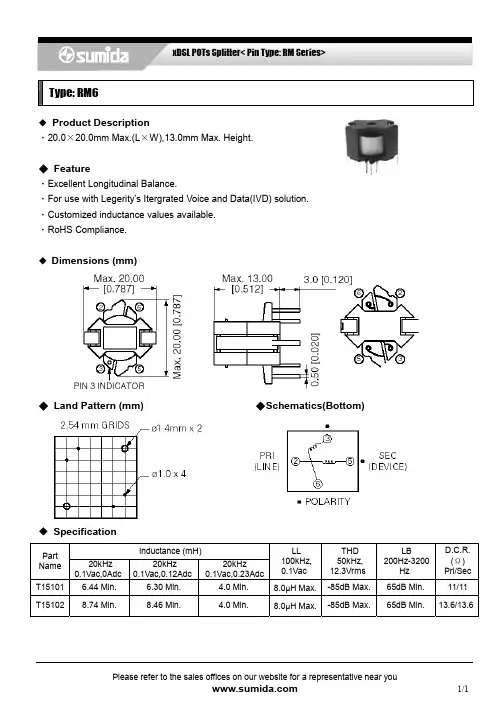
xDSL POTs Splitter< Pin Type: RM Series> Type: RM6
Please refer to the sales offices on our website for a representative near you 1/1 ◆ Product Description ・20.0×20.0mm Max.(L×W),13.0mm Max. Height. ◆ Feature ・Excellent Longitudinal Balance. ・For use with Legerity’s Itergrated Voice and Data(IVD) solution. ・Customized inductance values available. ・RoHS Compliance. ◆ Dimensions (mm) ◆ Land Pattern (mm) ◆Schematics(Bottom) ◆ Specification Inductance (mH) Part
Name
20kHz
0.1Vac,0Adc
20kHz
0.1Vac,0.12Adc
20kHz
0.1Vac,0.23Adc
LL
100kHz,
0.1Vac
THD
50kHz, 12.3Vrms LB 200Hz-3200Hz D.C.R.(Ω) Pri/SecT15101 6.44 Min. 6.30 Min. 4.0 Min. 8.0μH Max.-85dB Max. 65dB Min. 11/11 T15102 8.74 Min. 8.46 Min. 4.0 Min. 8.0μH Max.-85dB Max. 65dB Min. 13.6/13.6 元器件交易网

TB-9000 Page 1 of 4© 2018 DESCO INDUSTRIES INCEmployee Owned
SCS - 926 JR Industrial Drive, Sanford, NC 27332East: (919) 718-0000 | West: (909) 627-9634 • Website: SRMETER2 Surface Resistance MeterInstallation, Operation and Maintenance
DescriptionThe SCS SRMETER2 Surface Resistance Meter is a portable battery powered checker fitted with built-in parallel electrodes that allow for tests of material surface resistance. This meter is designed for quick checks of surface resistance for ESD control applications in electronics manufacturing or handling environment. The Surface Resistance Meter is equipped with an automatic test voltage selector. The test voltage will switch from 10V to 100V should the measured resistance exceed 1 x 10⁵ ohms. Two banana jacks and an electrode toggle switch allow for the connection of two external 5 pound electrodes that measure surface resistance point to point (Rtt) or resistance to equipment ground (Rtg).December 2018ESD protected area products should be tested:A. Prior to installation to qualify for listing in user’s ESD control plan. Approved ESD materials (see product qualification table at ANSI/ESD S20.20 Table 3 EPA ESD control items).B. During initial installation.C. For periodic checks of installed products as part of ANSI/ESD S20.20 Compliance Verification testing per ESD pliance Verification Plan“A Compliance Verification Plan shall be established to ensure the Organization’s fulfillment of the technical requirements of the ESD Control Program Plan. Process monitoring (measurements) shall be conducted in accordance with a Compliance Verification Plan that identifies the technical requirements to be verified, the measurement limits and the frequency at which those verifications shall occur. The Compliance Verification Plan shall document the test methods and equipment used for process monitoring and measurements. If the test methods used by the Organization differ from any of the standards referenced in this document, then there must be a tailoring statement that is documented as part of the ESD Control Program Plan. Compliance verification records shall be established and maintained to provide evidence of conformity to the technical requirements.The test equipment selected shall be capable of making the measurements defined in the Compliance Verification Plan.” (ANSI/ESDS20.20 section 7.3) The Surface Resistance Meter is not recommended for use in Resistance to Ground (Rtg) measurements.Packaging1 Surface Resistance Meter1 9V Battery1 Certificate of CalibrationMade in theUnited States of America USER GUIDE TB-9000

2SA1037AK / 2SA1576A / 2SA1774 /Transistors 2SA2029 / 2SA933ASGeneral Purpose Transistor
(−50V, −0.15A)
2SA1037AK / 2SA1576A / 2SA1774 / 2SA2029 /2SA933AS
!Features1) Excellent hFE linearity.2) Complements the 2SC2412K /2SC4081 / 2SC4617 / 2SC5658 /2SC1740S.
!StructureEpitaxial planar type.PNP silicon transistor!External dimensions (Units : mm)2SA1037AK
Abbreviated symbol : F ∗
Abbreviated symbol : F ∗Abbreviated symbol : F ∗
∗ Denotes hFEAbbreviated symbol : F ∗ROHM : SMT3EIAJ : SC-59(3) Collector(1) Emitter(2) BaseEach lead has same dimensions0.80.150to0.10.3to0.61.1(2)(1)
2.81.60.4(3)2.91.90.950.95
2SA1774
ROHM : EMT3EIAJ : SC-75A(3) Collecto(1) Emitter(2) Base0.70.150.1Min.0.550to0.10.21.61.61.00.30.8(2)0.50.5(3)0.2(1)2SA1576A
ROHM : UMT3EIAJ : SC-70(3) Collector(1) Emitter(2) BaseEach lead has same dimensions1.252.10.3

SACE Emax 2
Dispositivo Fail Safe - E2.2-E4.2-E6.2Fail-safe device - E2.2-E4.2-E6.2Fail-safe-Vorrichtung - E2.2-E4.2-E6.2Dispositif Fail Safe - E2.2-E4.2-E6.2Dispositivo Fail Safe - E2.2-E4.2-E6.2Doc. N.° 1SDH001400R0821- L8775
E2.2-E4.2-E6.2
12OK
OK1
2
ABCDE
x2F
SACE Emax 2 | ABB1
290°12
3
1
12221
2121
SACE Emax 2 | ABB3
4With undervoltage release - YU - installedWith undervoltage release - YU - installed
31GH25
6
SACE Emax 2 | ABBWith KLP or PLP installedWith undervoltage release - YU - installed
11.5 Nm
32
13.28 lb in GH
KIJ
SACE Emax 2 | ABB78MNL
E
ABCD2.2 Nm19.47 lb in 9
10
SACE Emax 2 | ABB12
CLICK!F
21
C
C
SACE Emax 2 | ABB11
12With KLP or PLP installed8.6 Nm76.1 lb inMNL
KIJ
1.5 Nm13.28 lb in13
14
90°23
1
© Copyright 2013-2014 ABB. All rights reserved.
For more information please contact:ABB S.p.A.ABB SACE DivisionVia Baioni, 3524123 Bergamo - ItalyPhone: +39 035 395 111Fax: +39 035 395 306 - 43312