posalux钻孔机说明书
- 格式:doc
- 大小:923.00 KB
- 文档页数:33
72” 3pt Cultipacker OWNER’S MANUAL
WARNING: Read carefully and understand all ASSEMBLY AND OPERATION INSTRUCTIONS before operating. Failure to follow the safety rules and other basic safety precautions may result in serious personal injury.
-MODEL # FTF-0631CP3PT -
12192017 2
Thank you very much for choosing this product! For future reference, please complete the owner’s record below: Model: FTF-0631CP3PT Purchase Date: _______________ Save the receipt, warranty, and these instructions. It is important that you read the entire manual to become familiar with this product before you begin using it.
This product is designed for certain applications only. The manufacturer cannot be responsible for issues arising from modification. We strongly recommend this product not be modified and/or used for any application other than that for which it was designed. If you have any questions relative to a particular application, DO NOT use the product until you have first contacted us to determine if it can, or should, be performed on the product.
Deep Hole Gun Drills940 Water Street, N. Bennington, VT 05257 • TOLL FREE: 888-338-1049 • Fax: 802-442-6225ToolholdersA variety of toolholding and reduction sleevesfor most machines (12)The TWINMASTER ®deep hole drillThe features and applications for a completely new two flute deep hole drill (13)Ordering and resharpeninginformation (14)A description of Sterling Gun Drills’ DM2000 and DM3000 kits,explaining the principle of their operation andapplication (15)Tear out and save A listing of styles and characteristics available. We offer gun drills from stock, or we can make custom drills tomachines ..........................................The DM-43 regrinding systemA self contained machine for gun drills and half round drills that can be used (8)The deep hole drilling systemA listing of components for deep and precision hole Gun Drills and Half round drillsA description of Gun drills and half round drills, specifi-cations, and ordering information (11)940 Water Street, N. Bennington, VT 05257 • TOLL FREE: 888-338-1049 • Fax: 802-442-6225Drill TipSingle flute solid carbide drill tips are supplied in all diameters from .078” to 1.625” in a number of styles.940 Water Street, N. Bennington, VT 05257 • TOLL FREE: 888-338-1049 • Fax: 802-442-6225Single Flute Gun DrillsA round or kidney oil hole is Sterling Gun Drills940 Water Street, N. Bennington, VT 05257 • TOLL FREE: 888-338-1049 • Fax: 802-442-6225940 Water Street, N. Bennington, VT 05257 • TOLL FREE: 888-338-1049 • Fax: 802-442-622512o20oD/440o12o25o35ofor most solid drilling holes, very deep holes,angled entry, exit. Not recommended for veryshort holes or high nickel alloys.15o20o25o30o20o12oD/412o20o15o20o15oD/425o30o15o20oD/310o25oFor special materials,please consult your Sterling Gun Drills representative.N-4: Aluminum grind, sweep or facetAllows more oil to fluteN-13: Cast iron grind, sweep or facetGood size controlN-73: Stack grind, sweep or facetGood for layered materialsGun Drill Regrind FixtureCapacity: .156 - 1.25” (DM41) .750 - 2.125 (DM42) The Sterling Gun Drills manual regrind fixture provides a fast and easy method of resharpening gun drillsand half round drills with the popular facet style grind. Drills of a large diameter range are positioned and ground without the need of expensive bushingsor collets. The universal nature of the fixture allows standard or custom regrinds.The Sterling Gun Drills Gun DrillRegrinding Fixture consists of threewith clamping device to holdeither a single flute gun drill or half round drill ingraduated in degrees, to allow the drill to be aligned in the vertical plane. This scale ismounted on the vertical member of the fixture that mounted on the diamond-shaped base of the fixture to allow the drill to be angled in the horizontal plane. This scale is also graduated in degrees.Both scales have locking levers to maintain vertical and horizontal positioning, and when used together allow compound angles to be ground on the nose of the drill mounted in the workhead.The fixture is normally used on a tool and cutter grinder equipped with a 11V9 or 11A2 style diamond wheel (120 - 150 grit). Some may choose a metal or plated bond wheel with concentric roughing and finishing faces, the roughing face having a coarser grit than the finishing one. The spindle of the grinding wheel will start at 90 degrees to the table slideway.940 Water Street, N. Bennington, VT 05257 • TOLL FREE: 888-338-1049 • Fax: 802-442-6225Standard items include:•Portable grinding machine•Protractor and drill regrind tables•Toolholder for gun drills andhalf round drills•360 grit wheel•Wheel wrench•Cleaning stick, spray bottleand wetting agent940 Water Street, N. Bennington, VT 05257 • TOLL FREE: 888-338-1049 • Fax: 802-442-6225940 Water Street, N. Bennington, VT 05257 • TOLL FREE: 888-338-1049 • Fax: 802-442-6225Stationary and Rotary ToolholdersA complete selection of stationary and rotary toolholders fit standard and CNC machine tools. Most Sterling Gun Drills' can adapt to these toolholders with available reduction sleeves.LubricantAs an atomized mist, this DM-43DM3000This three piece assembly consists of a solid carbide tip, an aircraft alloy formed tube shank, and industry standard driv-ers sized to allow use of these units diameter Regrind FixturesThree styles of regrind fixtures are available from Sterling DM-41/DM-42940 Water Street, N. Bennington, VT 05257 • TOLL FREE: 888-338-1049 • Fax: 802-442-6225The Deep Hole Drilling System Setup Procedure:Cutting area Point positionBurnishing areaRotary toolholderWorkpieceHalf round flute Also, Gun DrillsAir/mist passageMachine spindleAir/mist pathChip, air and coolantreturn pathSpraymist coolant unitThe gun drill and half round drill standard drill point position is offset to 1/4 of the drill’s diameter. This does not allow the drill to start unless guided by either a gun drill bushing or a pilot hole. On conventional machinery, a pilot hole is usually the most practical.Should you have any questions regarding materials, speed and feed, machine application or operation, contact Sterling Gun Drills for assistance.Step 1: Mix lubricant at a 10:1 ratio in a separate container, and fill the reservoir.Step 2: Prepare a pilot hole for the gun drill or half round drill to a diameter of +.001”, -0, by 1/2 to 1 diameter deep.If tolerances require, keep the pilot hole diameter closer but NEVER undersize. NOTE: Standard gun drills are not measurable, prepare the pilot hole as above to the label diameter.Step 3: Secure drill in toolholder mounted in the spindle, turret, or toolpost, true to the part or spindle center line.Connect nozzle from the Spraymist kitto the male fitting of the toolholder, or transfer block on a CNC.Step 4: Connect the Spraymist kit to shop air at100-120 psi. Select the proper running parameters from the Sterling Gun Drills' Speeds and Feeds Chart.Step 5: Insert the drill tip into the prepared pilot holejust short of the bottom. Start the spraymist by openingup the slide valve, adjust the mist jet needle to create a fine mist. (A white ring will be visable at the bore opening during the drilling.) Caution: NEVER rotate the drill outside of the hole.Step 6: Turn on the spindle, then start the feed. Chips should clear the bore continuously. to depth. If packing occurs, reduce the feed. At depth, back off the bottom slightly if a blind hole then stop everything andDriver (inch) ShankExample: GA 02500 2200The Half Round Drill(described as flute length or drill depth)Driver (metric) Shank (described as flute length in mm)Example: HA 02500 0180 Tip (drill diameter described as inch) Drill type Diameter Overall lengthStationary: Turret lathe and CNC Stationary: Engine lathe Rotating: Morse taper Rotating: Plain shankDL D2Reduction sleevesSpecial reduction sleeves can be supplied to order.two flute deep hole drill isa technologically superior, solid carbide tipped, tubular construction drill manufactured to any diameter from .20" (5 mm) to 1.00" (25.4 mm), with overall lengths todrill offers a choice wherethe extreme accuracy of a single flute drill is not certainly a better method) than twist drilling isgun drill machine. The advanced tip geometry and chip clearance advantage allow deep hole drilling in a wide variety of materials- not in just the "gray cast iron or free chipping nonferrous material" as limited by competitor's drills. Typical accuracy on standard machine tool applications should maintain .002" on diameter and better than.002"/inch straightness, with good surface finish. Better accuracy can be achieved on gun drill machines. Optional surface coatings include TiN, TiAlN, and others.Sterling Gun Drills offers a resharpening servicedrillsas well as our gun and half round models. Retipping isOther Sterling Gun Drills Products and Services:Half round drills • Speed drills • Spraymist kits • Gun reamers • Toolholders, lubricantRegrinding Information:TWINMASTER ® two flute drills can beresharpened many times, maintaining optimum performance, and used up drills or damaged drills with good tubes can be retipped. The 30o6o125oPoint thinning =Web thickness x 0.25Web thicknessNon-standard drivers can be made to order2 3/4"TWO TAPERED FLATS16 mm 25 mm 40 mm50 mm60 mm1" or 4"ApplicationSterling Gun Drills DM2000 and DM3000 Spraymist Kits are suitable for most machine tools from manual lathes and milling machines to CNC turning andmachining centers. Some manual machines with a limited speed and/or feed range will be more suitable if modified to achieve a workable rate. Vertical machines must be DM2000:One gallon (4 liter) capacityEach Spraymist kit includes: • Spraymist kit• 8 foot dual hose assembly • High flow mist jet Spraymist kits are specifically designed for carbide tipped, coolant fed drills to produce precision anddeep holes. The kit consists of a pneumatically operated piston pump delivering air and pressurized lubricant through a flexible dual hose assembly and a high flow Four gallon (15 liter) capacitySERVICES•Gun drill machine accessories •Coatings: TiN, TiAlN, plus others •Sharpening•Retipping, resizing•Specialized system parts •EXPERT ENGINEERINGDRILLING SYSTEMS•Spraymist kits •Tool holders •Lubricant•Regrind machine and fixturesCARBIDE DEEP HOLE DRILLS•Solid carbide head •Solid carbide flute •Gun reamers •Half round drills•“Twinmaster ®” Two flute drillsYour complete deep hole drilling source for:。
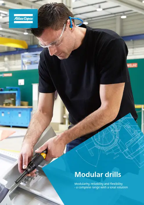
LBP16MHandheld drilling has never been more flexible.It is never just a drill. Wether you are building an aircraft, assembling a car or manufacuting a windmill, your choice of drilling tools determines how accurate the result becomes.The correct angle and point of entry is an important issue – with a surprisingly simple solution. Atlas Copco offers a complete tool, with one powerful motor unit, completely interchangeable with different heads, giving you a total solution. Whether it is steel or composite – you will have a perfect result.The lubrication free motor means a cleanerworking environment. A complete SEAL module keeps dust out of the motor, and the adjustable air exhaust directs the cool air away from the operator.The Pistol Motor modelsWith a range of six pistol motor models you will have no trouble finding a tool thatsuits your exact need.The rubber grip makes sure it lies perfectly in hand with wings and a round edged trigger to better fit and steadythe finger. T he smaller rear end and the handle angle is optimal for a comfortableworking position.BCFEGDHIALBD16MKFeaturesThe Straight Motor models With a range of six straight motor models – three models with low speed motor and three with high speed – you can besure to meet a perfect match.The rubber grip and safetytrigger make sure you avoidunintended starts and the reliable motor lies comfortable in hand. T he operator can easily adjust speed and power foroptimized drilling.CE IJA A Lubrication free motormeans a cleaner workingenvironment.B A small rear end for a goodfit to the hand.C Comfortable rubber grip.D Correct handle angle fora comfortable workingposition.E Adjustable air exhaustdirects the cool air awayfrom the operator.F Trigger with rounded edgesfor a good fit to the finger.G Speed control trigger.H Wings guide the operators’finger for a steady grip.I Dust and dirt stay out of themotor thanks to a completeSEAL module.J Safety T rigger to avoidunintended start.K Speed adjuster.Drilling behind a panel, at an angle…not a problem.MODULAR DRILL HEADS-DIMENSIONSStraight Head1234567891. BHM90EZC-6-62. BHM90ZC-6-63. BHM90EZT -1-44. BHM90ZC-5-0A wide variety ofangle heads guarantee you to find an optimal solution for your drilling needs. All angle heads in the BHM-series have a freewheel – making it easy to fit them into the motor unit.1011121314155. BHM0C-5-06. BHM90C-5-07. BHM30C-5-08. BHM30C-6-69. BHM45C-5-010. BHM90C-6-611. BHM90C-8-012. BHM90EC-5-013. BHM30ET -1-414. BHM30EC-6-615. BHM45EC-5-016. Extension for chuck16MODULAR DRILL MOTOR UNITSMODULAR DRILL HEADSaT he free speed is given when used with a 90° angle head. b Multiply this value with the Speed ratio to get the free speed of each angle head.For more information regarding off-set drills, please contact Atlas Copco local sales representativeModelStraight motor unitsExtension for Chuck(3/8”-24 UNF)Safety LeverCOLLETS FOR 5.0 MM CAPACITY HEADS (BHMC-5-0)COLLETS FOR 6.6 MM CAPACITY HEADS (BHMC-6-6)COLLET FOR 8.0 MM CAPACITY HEAD (BHM90C-8-0)SERVICE KITSKey wrenches,Collet or chuck with key3 mm collet (5.0 collet capacity head)6 mm collet (6.6 collet capacity head)8 mm collet (8.0 collet capacity head)ACCESSORIES INCLUDED OPTIONAL ACCESSORIES Short Lever9833 2006 01, 2020:1 © A t l a s C o p c o A B , S Atlas Copco AB(publ) SE-105 23 Stockholm, Sweden Phone: +46 8 743 80 00Reg. no: 。
电动钻操作指南说明书先前先俺沟。
操作电动钻时,请确保您已经了解并且理解了所有安全事项和技巧。
本指南将为您提供使用电动钻的详细说明,以确保您能够正确、安全地操作。
1. 准备工作在开始使用电动钻之前,您需要做一些准备工作。
1.1 确保工作区域安全无障碍物。
1.2 穿戴适当的个人防护装备,包括安全眼镜、耳塞和手套。
1.3 检查电动钻的电源线是否完好无损,并与可靠的电源连接。
2. 使用电动钻接下来是使用电动钻的详细步骤。
2.1 调整钻头根据您的需求,选择合适的钻头。
将钻头插入电动钻的钻头夹紧装置中,并紧固好。
2.2 调整扭矩和转速根据您要处理的材料和工作要求,调整电动钻的扭矩和转速。
对于较硬的材料,使用较高的扭矩和转速。
2.3 定位和标记确定您要钻孔的位置,并使用标尺或直尺标记出来,以保证准确度。
2.4 开始钻孔将电动钻垂直放置在标记的位置,握紧手柄。
轻轻按下电源开关,开始钻孔。
保持匀速和稳定的压力,避免过度用力。
2.5 清理完成钻孔后,关闭电动钻的电源开关。
用刷子或气压设备清除孔洞中的剩余材料和灰尘。
3. 安全事项在使用电动钻时,务必遵循以下安全事项。
3.1 始终佩戴个人防护装备。
3.2 避免触摸钻头和机身,尤其是在运行时。
3.3 在使用前检查电动钻的电源线和插头是否有损坏。
3.4 不要将手指放入钻头夹紧装置或工作区域内。
3.5 避免过度用力,以免引起意外伤害。
4. 维护保养正确的维护保养将延长电动钻的使用寿命。
4.1 定期清洁电动钻,特别是钻头夹紧装置和开关按钮。
4.2 使用适当的润滑剂对电动钻的机械部件进行定期润滑。
4.3 存放电动钻时,应将其放置在干燥、通风良好的地方,远离火源和潮湿的环境。
希望本指南能够帮助您正确、安全地使用电动钻。
请始终遵循安全操作规程,并严格遵守使用者手册中的指示。
祝您工作顺利!。
电动钻使用说明书尊敬的用户:感谢您选择我们的产品。
为了方便您正确并安全地使用我们的电动钻,我们准备了以下使用说明。
请您仔细阅读,并按照描述的方法来操作。
一、产品概述我们的电动钻是一款高性能的电动工具。
它具有以下特点:1. 功能强大:电动钻可以进行打孔、打磨、旋转等多种操作,适用于各种材料,如木材、金属、混凝土等。
2. 安全可靠:采用了先进的安全保护装置,如过载保护、电流保护等,确保用户的安全使用。
3. 操作简便:电动钻具有人性化的设计,操作简单、便捷。
二、安全须知在使用电动钻之前,请确保您已经仔细阅读并理解以下安全须知:1. 电源接入:使用前,请确认电动钻的电源适配器已正确接入交流电源,并且确保电源稳定可靠。
2. 个人保护:在使用电动钻时,请佩戴符合相关标准的防护眼镜、手套和耳罩等个人防护装备,以确保您的安全。
3. 工作环境:使用电动钻时,要确保工作环境干燥通风,并远离易燃、易爆等危险物品。
4. 脱离电源:在开始维修、清洁、更换配件等操作之前,请务必先将电动钻断开与电源的连接。
三、操作指南为了使您更好地操作我们的电动钻,以下是一些使用技巧和操作指南:1. 选择合适的钻头:根据需要,选择合适的钻头进行操作。
钻头的直径和材质要根据工作需求来选择。
2. 安装钻头:用配套工具打开电动钻的钻头夹紧装置,安装钻头,并确保其牢固。
3. 调节转速:根据不同的工作需求,通过电动钻上的调速钮来调节转速。
要根据具体工作材料和工作方式来选择合适的转速。
4. 握紧电动钻:握紧电动钻的手柄,保持稳定。
在操作时要保持垂直,力量均匀。
5. 开始操作:确认一切准备就绪后,按下电源开关,缓慢开始操作。
注意避免将电动钻的钻头与物体发生剧烈碰撞。
四、维护保养为了保持电动钻的良好工作状态,并延长使用寿命,以下是一些建议的维护保养方法:1. 清洁:使用完毕后,请用干净的布擦拭电动钻的表面,并注意不要让水或其他液体进入电动钻内部。
2. 润滑:定期将适量的润滑油滴入电动钻的轴承部分,以保持良好的工作状态。

150型钻机使用说明书河北省电力勘测设计研究院勘测工程部目录1 150型钻机性能及主要参数 (1)2 一般性规定 (1)3 准备和检查 (1)4 钻机的安装、拆卸与搬运注意事项 (2)5 钻进注意事项 (2)6 150型钻机操作程序 (3)6.1 场地平整与钻机就位 (3)6.2 钻机塔架安装 (3)6.3 钻进 (3)6.4 钻塔拆卸 (3)6.5 钻机场内搬运 (4)6.6 钻机装卸车 (4)1150型钻机性能及主要参数该钻机是我院对新购置150型钻机装卸车部分进行改进,其它性能不做任何改变,以减轻钻机重量,减少装卸车安全隐患。
该钻机与DPP100型钻机相对具有小型轻便,易于进出场,占、赔地面积小,功能齐全等特点。
适合大型钻机不能到达或施工场地较困难的地区钻探,具有良好的循环水系统,适合各类地层钻探。
150型钻机主要性能及参数如下:150型钻机技术参数2一般性规定为了保证施工安全,在使用本150型钻机前请仔细阅读下列注意事项。
a)使用前,必须阅读这本说明书,并确信按照该指导使用本钻机。
使用不正确可能会造成伤害,建议有经验的人员使用。
b)使用本钻机时,必须在清醒状态下,全神贯注,操作时应顾及其他人员安全。
疲劳或生病时候,绝对不可以使用本钻机。
c)在工作时,严禁穿戴围巾和摇摆的衣物,并穿戴防护用品。
3准备和检查a)出工前要对钻机、设备、工具、材料进行认真检查,确保钻探所用工器具齐全。
b)准备必要配件和易损件,以便及时维修。
c)场地必须坚固、平整、适用。
钻机底部填方部分不得超过其面积的1/4,填方部分应采取措施防止塌陷与溜方。
d)在悬崖、陡坡下工作时,应避开危岩崩落区,并将坡体活石清除。
4钻机的安装、拆卸与搬运注意事项a)钻机装卸车要有专人统一指挥,必须装好塔架底座。
b)塔架安装时必须在确保两支后腿塔架固定牢固,前后腿保证基本平行。
c)钻机由一个钻孔移至下一个钻孔时,必须放下塔架,由钻机牵引或人工推拉到达。
日立HITACHI钻孔机操作手册HITACHI钻孔机操作说明一、钻孔机本体及周边设备介绍钻孔机本体:前视图钻孔机本体:后视图周边设备:1、油冷机:冷却主轴(spindle),保证主轴在规定的温度下工作2、干燥机:过滤空气中的水份、油份及各种杂质,保证机台入口侧的空气品质符合日立标准。
二、机台对环境的要求1、电力要求电压:三相200V/50Hz功率:15KVA(18KVA:含集尘机)2、气压要求压力:590--690 kPa(6.0—7.0kg/cm2 ) 流量:900 L/min气温:20±5℃固体颗粒:Max.0.01 micron (.0004mil) 去油率:≥99.9999%气管内径:19mm3、集尘要求负压:140mm Hg流量:4000 L/min管径:75mm4、环境要求,操作画面介绍3、加工画面(F1)NUMBER: 工具群组(表示钻针置于钻针盘的位置)GROUP 加工番号(表示程序中目前夹取T**的针)DIAM 工具直径(表示目前S/P夹头中夹取的钻针尺寸) MITS 孔数(表示使用中的钻针已经加工多少孔数) MAX HIT 寿命(表示使用中的钻针设定的寿命孔数) OFFSET 补偿值(表示使用中的钻针设定增加或减少的补偿值) SPEED S/P转速(表示使用中钻针的转速)INFEED 进刀速(表示使用中钻针的进刀速度)RTR 退刀速(表示使用中钻针加工后,退刀的速度) UP LIMIT 加工上限(下钻后钻针抬起来,距离桌面的最大高度) DN LIMIT 加工下限(下钻时钻针距离桌面的最低高度) PROGRAM(右上角) 程序(显示目前加工中的程序指令区块位置)可以更改选择以(孔数hit)或(时间time来表示) Hit (上一趟的孔数)Prog.Hits(目前已经加工的孔数)4、工具条件画面(F2)这个画面是显示加工条件及设定1>NUMBER﹕显示工具编号2>GROUP﹕加工番号(T群组)3>DIAM﹕工具直径4>HITS﹕加工孔数5>MAX HIT﹕工具寿命6>INFEED﹕Z轴进刀速7>DWELL﹕钻孔循环机械停留时间8>PECK﹕分段加工数据编号9>TESTH﹕测试孔设定ON/OFF10> BH﹕盲孔加工有效/无效(选购机能)11>SPEED﹕主轴转速5、工具补正页DIAMETER TABLE (直径表)此一画面为DIAP画面可作各种直径之加工条件设定使用本机能,将每一种钻径的钻针设定适当的加工条件.以便只要在F2画面中输入钻径.其它的加工条件就会出现,这样就能缩短设定加工数据的时间。
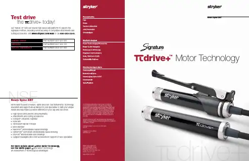
Neuro Spine ENTdrive+™Motor TechnologyStryker I.D. Touch™ software: A difference you can feelA surgeon’s “touch” is one of his/her greatest assets, and our industry-exclusive I.D. Touch software aims to support this. Within the CORE TM Console power source, I.D. Touch software enables you to adjust torque from 0-100% to customize how your electric drill responds whenpressure is applied during use – from low to high sensitivity – redefining performance to your liking. Your NSE sales representative can guide you through the options, and save the performance and feel that’s right for you in user preferences.Power to get thejob done quicklydrive+ Electric Motor100%80%60%40%20%0%I .D . T o u c h S e t t i n gMost Sensitive Least SensitiveMotor SensitivityLow-friction coating helps to reduce friction and the collection of debrisOptional motor extender for enhanced grip options and ergonomics60% more powerful than the drive motor242% more torque at max speed of 75K RPMsdrive Motor TechnologyPowered by the Stryker CORE Console which:- Customizes drill response via its I.D. Touch software- Enables connectivity with threehandpieces, two foot pedals, the Stryker Bone Mill and irrigation cassette- Creates and stores unlimited user profiles34% lighter than the Sumex ® high performance drill Multi-notch Elite telescoping cutting accessory245% more volumetric optimization than Sumex60% more powerfulThe drive+ electric motor gives you an added 60% boost in power –and 242% more torque at its max speed of 75K RPMs – over its companion drive™ motor so you can handle rigorous tasks quickly and effectively. And this high power won’t come at the expense of other preferences. You can use the drive+ motor with or without a handswitch, with an optional motor extender for more grip space, and with nearly 100 new attachments and cutting accessories in the Signature Portfolio, the most comprehensive and customizable high speed drill platform in Stryker’s 70 year history. Take a closer look at the drive+ motor below.The drive+ motor design builds upon our original patented drive design, which re-imagined the conventional motor by:• Replacing a nonfunctioning steel core with magnets in a “pie” configuration • Fully encasing the core with flat wire winding as opposed to an open loop design• Creating volumetric optimization by reconfiguring internal components in ways that enhance performance, optimize space and limit housing size • Allowing you to customize how the drill responds and feels via I.D. Touch™ software within Stryker’s CORE™ ConsoleMotorMagnets ™™Flat Wire casingConventional Electric MotorDetachable handswitch。
150型钻机使用说明书河北省电力勘测设计研究院勘测工程部目录1 150型钻机性能及主要参数 (1)2 一般性规定 (1)3 准备和检查 (1)4 钻机的安装、拆卸与搬运注意事项 (2)5 钻进注意事项 (2)6 150型钻机操作程序 (3)6.1 场地平整与钻机就位 (3)6.2 钻机塔架安装 (3)6.3 钻进 (3)6.4 钻塔拆卸 (3)6.5 钻机场内搬运 (4)6.6 钻机装卸车 (4)1150型钻机性能及主要参数该钻机是我院对新购置150型钻机装卸车部分进行改进,其它性能不做任何改变,以减轻钻机重量,减少装卸车安全隐患。
该钻机与DPP100型钻机相对具有小型轻便,易于进出场,占、赔地面积小,功能齐全等特点。
适合大型钻机不能到达或施工场地较困难的地区钻探,具有良好的循环水系统,适合各类地层钻探。
150型钻机主要性能及参数如下:150型钻机技术参数2一般性规定为了保证施工安全,在使用本150型钻机前请仔细阅读下列注意事项。
a)使用前,必须阅读这本说明书,并确信按照该指导使用本钻机。
使用不正确可能会造成伤害,建议有经验的人员使用。
b)使用本钻机时,必须在清醒状态下,全神贯注,操作时应顾及其他人员安全。
疲劳或生病时候,绝对不可以使用本钻机。
c)在工作时,严禁穿戴围巾和摇摆的衣物,并穿戴防护用品。
3准备和检查a)出工前要对钻机、设备、工具、材料进行认真检查,确保钻探所用工器具齐全。
b)准备必要配件和易损件,以便及时维修。
c)场地必须坚固、平整、适用。
钻机底部填方部分不得超过其面积的1/4,填方部分应采取措施防止塌陷与溜方。
d)在悬崖、陡坡下工作时,应避开危岩崩落区,并将坡体活石清除。
4钻机的安装、拆卸与搬运注意事项a)钻机装卸车要有专人统一指挥,必须装好塔架底座。
b)塔架安装时必须在确保两支后腿塔架固定牢固,前后腿保证基本平行。
c)钻机由一个钻孔移至下一个钻孔时,必须放下塔架,由钻机牵引或人工推拉到达。
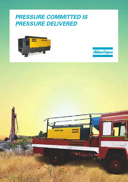
PRESSURE COMMITTED IS PRESSURE DELIVEREDRESALE VALUEYou.Not usSolutions.Not compromiseEngineered.Not assembled HIGH2Robust, reliable compressors for water well drilling engineered with the highest standards ensuring low cost of ownership.BREAKTHROUGH TECHNOLOGY FOR WATER WELL DRILLING3* According to ISO1217 ED3 1996 Annexure DTECHNICAL DATAPRODUCT FEATURESSound dampened, powder coated, strong steel canopy, validated for 50° C LAT and rugged usagePusher type fan toensure optimum coolingCompact air oil separator tankDischarge outlet best suited to the applicationTwo stage elements (less load on engine) - only for XRHS650 modelSpecially designed baffles to guide hot and cooling air Heavy duty filters for effective filtration Gull wing type doors for better access to all componentsMonitoring and performance settings on the same side (Dual pressure toggle switch ideal in back pressure situations)- only for XRHS650 modelUnique unloader valve design foroptimal performanceExtra hinge door for faster serviceabilityMOBILE• 9-1250* kVAINDUSTRIAL • 10-1250* kVAGENERATORSPORTABLE• 60-80-100 kVAPRODUCTIVITY PARTNER• 1000-1350 cfm • 19-35 barDEWATERING PUMPSELECTRICSUBMERSIBLE • 275-16.500 l/minDIESEL DRIVEN CANOPY• 833-9833 l/minDIESEL DRIVEN OPEN FRAME • 3300-7500 l/minLIGHT TOWERSLEDMETAL HALIDEELECTRICREADY TO GO • 160-412 cfm • 7-8.5 barVERSATILITY • 436-675 cfm • 10.5-20 bar*Multiple configurations available to produce power for any size application.Diesel and electric options available.Diesel and electric options available.Atlas Copco’s Power T PRODUCT PORTFOLIOL A P W S 1.5W W © 2018 A t l a s C o p c o P o w e r T e c h n i q u e . A l l r i g h t s r e s e r v e d .® A t l a s C o p c o i s a r e g i s t e r e d t r a d e m a r k o f A t l a s C o p c o A BSKumar:+919940686506,*********************.com,PrakashKhobragade:+919331411141,********************************.com,FenilShah:+917030464386,********************************************@Tollfreenumber180********AIR COMPRESSORSPhotos and illustrations contained herein might depict products with optional and/or extra components which are not included with the standard version of the product and, therefore, are not included in a purchase of such product unless the customer specifically purchases such optional/extra components. We reserve the right to change the specifications and design of products described in this literature without notice. Not all products are available in all markets.。
HITACHI钻孔机操作技能培训教材目录一.钻孔机外观构造认识二.机台保养1.机台局部各类保养△2.机台各类润滑保养〔此局部同厂商完成,只供了解〕三.机台开关机程序四.钻孔机触控屏幕操作使用介绍1.快捷操作键说明2.触摸屏幕操作说明五.机台操作画面的认识1.机台操作画面的构成2.共通键的操作3.机台操作画面分配及呼叫*六.机台各操作画面技能培训〔重点〕1.F1加工画面2.F1 加工状态显示3.F2 钻针刀盘各项参数设置4.刀径参数相关指令输入技能5.F3 分段加工设置6.F3 生产参数说明7.F4 生产象限与原点补偿设置△8.F4 生产坐标涨缩补偿设置〔此节内容仅供参考〕9.F4 SECOND UPLIMIP与PARK点指定位置设置10.F5生产程式格式设置11.F6工具高度检查设定画面△12.F6测试孔设置相关技能〔此节内容仅供参考〕13.F7钻针刀盘显示页14.F7主轴运转时数显示画面15.F8机台各项坐标显示画面16.F8机台系统参数与功能设置17.F8机台运行状态诊断显示画面*七.机台指令〔重点〕1.机台功能设定指令2.原点设定指令3.机床移动指令4.上,下限设定指令5.单位,位数设定指令6.程序执行相关指令八.机台各类故障明细1.加工孔时的故障2.断针的故障3.主轴的故障4.弹簧夹头的故障5.压力脚的故障6.主轴冷却装置的故障7.传动轴(X.Y.Z)的故障8.自动交换钻针(ADC)的故障9.确认工具高度的故障九.故障表1.报警信息的表示2.报警信息一览表一:钻孔机外观构造介绍1.钻孔机直观图片〔HITACHI 钻孔机图片〕FRONT VIEW REAR VIEW二:机台保养为了保证钻孔机主轴的寿命,生产精度及生产运作,所以钻孔机需定期做好相关各保养工作,具体如下表△2.机台相关滑油保养〔此局部内容由厂商完成,只供了解〕编号频率加油口位置润滑油系列使用工具加油口数量1 三个月一次X轴螺杆.滑轨ISOFLEXNBU15(KLUEBER)黄油枪 32 三个月一次Y轴螺杆.滑轨ISOFLEXNBU15(KLUEBER)黄油枪73 三个月一次Z轴螺杆ISOFLEXNBU15(KLUEBER)黄油枪 64 三个月一次Z轴滑轨AFC(THK)黄油枪125 三个月一次Z轴培林ALVANIANO.2(Shell oil)黄油枪12****使用正确的油脂并定期的给油,可延长机台的螺杆使用寿命。
ElectropunchMODEL CINSTALLATION, OPERATING, MAINTENANCE INSTRUCTIONSBlack & Webster Products Division545 Hupp Ave. P.O. Box 831Jackson, Michigan 49204Phone: (517- 787-9444 Fax: (517) 787-7585Email:**********************Model –C Serial Number: __________________PPK Serial Number: __________________2009Table of Contents Warranty (3)Installation (4)Operation (5)Maintenance (5)Troubleshooting (5)Disassembly (5)Dimensions & Specifications (6)Head Assembly Bill of Materials (7)Parts List (7)Machine Diagram (8)Press Dimensions (9)General Specifications (9)Preventative Maintenance & Trouble Shooting………………………………………. 10-12The Model C Electropunch is an electric high speed production tool for staking, riveting, marking, and punching.Upon receipt of your Model C Electropunch, inspect it for any damage that may have occurred during shipping. If there is damage, notify Air-Hydraulics, Inc. immediately. Study all instructions and drawings carefully before installation.ELECTROPUNCHThe Electropunch operates on the electromagnetic principal. Current for operation is 115 volt AC, 60 cycle, single phase (or 230 volt AC, 60 cycle, single phase, with a Power Pak) . Required “on” time of the palm buttons or foot switch is (1/10) of a second. In most applications, the impact is controlled through a variable transformer type impact controller (Power Pak) which allows the voltage to be varied to the solenoid coil. This adjustment results in a staking blow of a few pounds up to 3500 pounds or 8000 pounds with the Power Pak controller. With proper operation and maintenance, the Electropunch will give 2 or 3 million cycles (expected life of coil). Outlined below are recommended operation and maintenance procedures.Operation: Depressing the Dual Palm Buttons or Footswitch for longer than (1/10) of a second will tend to overheat the coil and consume an unnecessary amount of current which will shorten the expected life of the coil. Consequently, the control enclosure has a timer built-in to prevent the coil from being energized for less than (1/2) second. If purchased with out controls, the coil should not be energized for an extended length of time. An operator quickly learns the optimum time to hold the switch after familiarization of the machine’s operation.Important note: the Electropunch should never be “dry cycled” or cycled at maximum stroke. This will cause the spindle bearing to “roll” or “peen over” causing dragging or binding.Maintenance: There are only two moving parts in the Electropunch – the spindle and solenoid plunger. The spindle bearing should be lubricated every few days with two drops of ”Moluballoy” spindle oil. (A tube is provided with each machine.) If operation is in an area where dust or dirt may collect on the spindle, cleaning regularly is recommended. These contaminates tend to be “dragged” into the bearing at each stroke causing the Electropunch to become sluggish and reducing it’s power. If this occurs, the spindle and bearing should be disassembled and cleaned with “carbon tetrachloride” or other solvent. Wipe clean and apply two drops of “Moluballoy” oil when reassembling.Although the Electropunch is simple in operation and maintenance, the above procedures, if followed, will insure long, trouble-free operation.WarrantyAir-Hydraulics, Inc. warrants to the original user that all products manufactured will be free from defects in material and workmanship and will possess the characteristics represented in writing by us. Claim for breach of the above warranty must be made within a period of one year from date of delivery to the user. Upon satisfactory proof of claim, we will make any necessary repairs or corrections, or at our discretion, replace defective parts at the factory, transportation charges prepaid. Charges for correcting defects will not be allowed, nor can we accept goods returned for correction unless we are notified in writing and the return or correction is authorized by us in writing. The foregoing is in lieu of all other warranties, expressed or implied, including any warranties that extend beyond the description of the product. This paragraph set forth the extent of our liability for breach of any warranty in connection with the sale or use of our products. It is understood we will not be liable for consequential damages such as loss of profit, or expense, whether based on tort or contract. This warranty is void if the articles covered by the warranty have not been properly installed, maintained and used.InstallationMounting: See figure 1Wiring: The Model C is equipped with a Power Pak (control unit), and electrical cord, and a molded three-prong plug. See Power Pak installation instructions in Power Pak kit.Tools: The striking tool must have a shank .624 to .625 x 7/8” long with a shoulder on the shank which butts against the bottom of the spindle. Harden tool after machining for longer life.Set-up:1. Loosen the two large cap screws [fig. 2 (pg. 6), #17] that are holding the yoke clamp (fig. 2, #15). Next, loosen the four set screws [fig. 3 (pg. 7), #4] on the right side of the frame which hold the gib (fig. 3, #18) inposition. Caution- Excessive loosening will result in the gib falling out. 2. Position the head for easy access to the spindle. This is accomplished by using the hand-wheel on the elevating screw assembly (fig. 3, #19). 3. Install and lock tool in spindle. Pull spindle down and insert taper pin (fig. 3, #25) in hole provided. Insert work-piece in nest. Lower head until the tool engages the work-piece.4. Slightly tighten the four set screws, and then tighten the cap screws. Take the taper pin out of the spindle. Caution-If head is in the full down or up position, avoid excessive tightening of top or bottom set screws to prevent gib from bending.5/16-18 UNC-2B (2 )1.75 (44.5).52 slots (13.2)5.62 (142.88.00 (203.2) 11.00 (279.4 12.25 (311.23.25 (82.6)6.00 (152.4)5.000±.005 (127.00±.13)9.75 (247.7)OperationThe Model C Electropunch receives its power from the Power Pak. Closing the hand switch(es) or foot switch initiates the firing circuit, after which power to the Electropunch passes through this switch. The operator must hold the switch closed for 60 milliseconds for the Model C to achieve full power. Holding the switch longer will not overheat the Electropunch coil, as power is cut off by the Power Pak. The switch must be released to re-fire the machine. Power on the Model C Electropunch is varied by turning the control knob on the Power Pak.Operation: Depressing the Dual Palm Buttons or Footswitch for longer than (1/10) of a second will tend to overheat the coil and consume an unnecessary amount of current which will shorten the expected life of the coil. Consequently, the control enclosure has a timer built-in to prevent the coil from being energized for less than (1/2) second. If purchased with out controls, the coil should not be energized for an extended length of time. An operator quickly learns the optimum time to hold the switch after familiarization of the machine’s operation.Important note: the Electropunch should never be “dry cycled” or cycled at maximum stroke. This will cause the spindle bearing to “roll” or “peen over” causing dragging or binding.MaintenanceThere are only two moving parts in the Electropunch – the spindle and solenoid plunger. The spindle bearing should be lubricated every few days with two drops of ”Moluballoy” spindle oil. (A tube is provided with each machine.) If operation is in an area where dust or dirt may collect on the spindle, cleaning regularly is recommended. These contaminates tend to be “dragged” into the bearing at each stroke causing the Electropunch to become sluggish and reducing it’s power. If this occurs, the spindle and bearing should be disassembled and cleaned with “carbon tetrachloride” or other solvent. Wipe clean and apply two drops of “Molub-Alloy Lubricant” oil when reassembling. Remove the guard cover (fig 3, #8) to find the oil hole.TroubleshootingUnit does not operate1.Check all electrical connections to be sure electrical contact is being made.2.Check the solenoid. If it does not operate, check the coil for an open winding witha continuity test.3.See Power Pak installation and maintenance instructions.DisassemblyFor replacement of a coil or cleaning the spindle bearing, remove the guard cover and unscrew the lock nut found on top of the guide plate. Clamp a .625 dia. piece in the tool hole so that a wrench or other means may be used to hold the spindle from rotating when unscrewing the lock nut. If this is not done, the guide pin may end. After the guide plate has been removed, the spindle may be driven down through the armature and out through the bearing in the bottom of the solenoid.Dimensions and SpecificationsImpact Force lbs .ModelImpact in lbs. STD. Power PakOptionStroke Spindle to Base Min. Max. ThroatDepth Spindle ToolHoleTool Weight Weight lbs. C234n/a 15,0002.003.00 10.504.50.624/.627 x 1.007 lbs.90Bill of Material for Model C Head Assembly OnlyDetail # Part # Part Name Qty.1 200204 Core w/ Spacer and Bearing 12 200211 Spool Guide w/ Bearing 13 200226 Coil w/ Term Board 14 200231 Yoke 15 200232 Tool Holding Clamp 16 200234 Shock Pad 17 200235 Spindle 18 200237 Spindle Return Spring 19 200241 Armature 110 200242 Guide Plate 111 200245 Guide Pin 112 200247 Coil Insulator w/ Slot 113 200248 Coil Insulator 114 200251 Coil Hold-down Spring 115 200302 Yoke Clamp 116 36263 Locking Hex Nut 117 23918 Soc Hd. Cap Scr. 5/8-18 x 2½ long 218 33016 5/8 Flat Washer19 64077 Roll Pin 1/8 dia. x 5/8 long 120 23205 Soc Hd. Cap Scr. ¼-20 x 1 long 121 25502 Soc Hd. Set Scr. 5/16-24 x 1 long 222 36364 Hex Nut 5/8-18 123 26750 Dowel ¼ dia. x 5/8 long 124 200233 External Ring 1Optional Items8 200238 Spindle Return Spring-Heavy Duty1Bill of Material For Model “C” Electropunch AssemblyDetail. #Part # NameQty. 1 32212 RD HD Drive Screw #2x3/16 4 2 200125 200126 Name plate-115V 50/60 Hz -Other1 3 27282 RD HD Screw #6-32x ¼ LG 4 4 25403 Soc HD Set Screw ¼ -28x1” LG45 36252 Hex Nut ¼ -284 6 27357 RD HD Screw #8-32x ¼ LG 7 33708 Lock Washer #8 2 8 200297 Guard1 9 27530 RD HD Screw #10-32x ¼ LG 4 10 33708 Lock Washer #10 4 11 200317 Strain Relief1 12 33707Internal Tooth Lock Washer #6 1 13 C-HEADModel “C” Head Assembly 1 14 200299 Connection Box 1 15 200314Grommet1 16 76512-18-06Wire #16 AWG X 3” LG 1 17 0704741 Terminal Ring 2 18 200309 Gib1 19 200266 Elevating Screw Assembly 1 20 200308 Frame1 21 27378 RD HD Screw #8-32x ½ LG 1 22 200129 Cable Clamp 1 23 20008120 Coil Cable1 2445131Single Steel Jack Chain #18x12”125 101406 Taper Pin #2x1” 126 PPK-5-1 Model PK Power Pak Assembly 1B&W ELECTROPUNCH FAQ:1. I'M GETTING A DOUBLE HIT OR GHOST HIT, WHICH IS LEAVING A DOUBLE IMPRESSION WHEN WE’RE MARKING PARTS.ANSWER: THERE ARE TWO REASONS WHY THIS MAY OCCUR; 1ST, THE RETURN SPRING MAYBE WEAK OR FATIGUED, 2ND, THE RUBBER STOPPER ATTACHED TO THE TOP OF THE HEAD MAYBE WORN. REMOVE & REPLACE BOTH PARTS2. I AM USING A POWER PAK WITH MY ELECTROPUNCH AND A FOOT SWITCH OR SINGLE SWITCH TO CYCLE THE PUNCH, BUT IT WON'T FIRE. THE MAINTENANCE PEOPLE MAY OR MAY NOT HAVE BEEN WORKING ON IT.AANSWER: THE FOOT SWITCH - DUAL PALM (DIP) SWITCH, LOCATED ON BOTTOM WAS MORE THAN LIKELY SWITCHED TO DUAL PALM SETTING. MAKE SURE POSITION OF SWITCH IS SET FOR SINGLE OR FOOTSWITCH ACTIVATION3. BS/FJS/SMS/JS ELECTROPUNCH SPINDLE IS STICKING AND WON'T SLIDE EASILY DOWN OR UP, THEREFORE NOT CONSISTENTLY CYCLING OR DOESN'T SEEM TO HAVE THE FULL IMPACT FORCE.ANSWER: THE ELECTROPUNCH HAS BEEN "DRY FIRED/CYCLED" TOO MANY TIMES WHICH HAS CAUSED THE BOTTOM BRASS BUSHING TO DEFORM, COMPRESSING THE BUSHING AGAINST THE SPINDLE, ACTING LIKE A BRAKE. REMOVE & REPLACE BUSHING AND AVOID CYCLING THE ELECTROPUNCH WITHOUT BOTTOMING OUT. HAVE THE SPINDLE AND TOOL IMPACT AGAINST MATERIAL PRIOR TO SPINDLE COLLAR STRIKING AGAINST BRASS BUSHING.4. WHAT SHOULD THE DIP SWITCH SETTING BE FOR MY POWER PAK PPK-2/4?ANSWER: IF USING A M/D: BS, FJS, JS, SMS THE DIP SWITCH SETTING ARE NORMALLY: SWITCH (SW) 1 = OFF, SW 2 = OFF, SW 3 = ON, SW 4 = ONIF USING A M/D: "C", THE SWITCH SETTING ARE NORMALLY; SW 1 = OFF, SW 2 = ON, SW 3 = ON, SW 4 = ON5. CAN I USE MY POWER PAK, PPK-2/4, CONTROL UNIT ON OTHER ELECTROPUNCH UNITS?ANSWER: YES, BUT THE POWER PAK USED WITH A FOOT SWITCH ACTIVATED ELECTROPUNCH CAN NOT BE USED WITH ELECTROPUNCHES ACTIVATED WITH DUAL PALM BUTTONS, AND VICE VERSA. YOU CAN USE A POWER PAK FROM A M/D: BS, FJS, JS, AND SMS ON A M/D: "C" ELECTROPUNCH, AND VICE VERSA, BUT YOU MUST FIRST CHANGE THE DIP SWITCH SETTING, SEE MANUAL. AGAIN, THE ACTIVATING SYSTEMS MUST BE THE SAME.6. WHAT SHOULD THE OMHS MEASURE ACROSS THE LEADS ON A BS-230 VOLT COIL?Answer: APPROX. 1.5 OHMSMOD-C DOES NOT FIRE EVEN THOUGH THE PPK 2/4 INPUT LIGHT TURNS ON-WHAT CAN I CHECK?1)REMOVE THE COVER ON THE SIDE OF THE MODEL-C &CHECK THEWIRE CONNECTIONS & VERIFY THAT THEY ARE TIGHT.2)AT THE SAME LOCATION, WITH A VOLT/OHM METER, VERIFY THATTHE OHM READING OVER THE COIL IS 1.2-2.4 OHMS.3)WITH A VOLT/OHM METER, CHECK CONTINUITY FROM THE PPKOUTPUT PLUG END TO THE COIL CONNECTIONS ON THE SIDE OF THE MODEL-C ELECTROPUNCH.4)PPK 2/4 DIP SWITCH SETTINGS UNDER THE CAP COVER ON THEBOTTOM OF THE UNIT SHOULD BE SW 1=OFF, SW 2=ON, SW 3=ON, SW 4=ON.。
大量钻孔机说明书篇一:钻机说明书1 概述TSJ3000/445钻机采用机械传动、转盘式。
本机重心低,传动平稳,选材合理,坚固耐用。
主要特点为:密封性能良好,机械拧卸钻具,配备水刹车辅助抱闸装置,可降低卷筒、闸带的损耗。
本机适用于1500-2600m深的地下水、中浅层石油开采及地热开发、盐井钻进、煤层气开发等工程。
2 基本参数3 传动系统(附图一):钻机升降机和转盘的动力为两台Y280M-4电动机或一12V135-SM型柴油机。
通过磨擦离合器,将动力传入变速箱后,经齿式联轴节传入转盘,经对键轴传入升降机。
采用摩擦离合器可使钻机平稳的启动、钻进和停止,并能防止钻机过载,这对变速箱的变速及分动都是很必要的。
变速箱除变速外,兼起分动箱的作用。
变速箱中正、反两个伞齿轮分别与被动伞齿轮啮合,经输出轴传至转盘大齿轮,可使转盘分别得到正、反四个转速(r/min):一速:n1=901×(28/52)×(27/53)×(40/30)×(26/36)×(17/30) ×(26/82)=43二速: n2=901×(28/52)×(26/36)×(17/30)×(26/82)=63 三速:n3=901×(28/52)×(42/38)×(40/30)×(26/36)×(17/30)×(26/82)=93四速:n4=901×(40/30)×(26/36)×(17/30)×(26/82)=156 升降机转速(r/min)三种:慢速:n1=901×(28/52)×(27/53)×(40/46)×(46/74)×(34/102) =44.5中速:n2=901×(28/52)×(42/38)×(40/46)×(46/74)×(34/102) =96.6快速:n3=901×(40/46)×(46/74)×(34/102)=1624 结构简介(附图二):本机由10个部分组成:转盘、底座、动力机组、变速箱、联轴节、离合器、升降机、抱闸、水刹车装置、水路系统。
1標準畫面(Standard Table) (2)1.1 進入及使用標準畫面 (2)1.2 按鍵說明 (2)1.3 生產資料 (4)1.4 機台狀態 (5)1.5 其它 (8)2狀態畫面(Status Table) (8)2.1. 進入及使用狀態畫面 (8)2.2. 按鍵說明 (9)2.3. 詳細生產資料 (10)2.4. Skip功能說明 (11)3控制畫面(Console Table) (12)3.1. 軸控制(Machine Axis) (12)3.1.1. 按鍵說明 (13)3.2. 機台功能設定(Machine Setting) (15)3.2.1 按鍵說明 (15)3.3. 軸選擇(Station Select) (17)4系統參數畫面(System Parameters) (18)4.1 軸畫面(Axis Table) (18)4.2 格式晝面(Format Table) (20)4.3 設定畫面(Setting Table) (22)4.4 選項畫面(Option Table) (23)5刀具畫面 (24)5.1 刀具參數畫面(Technological Table) (24)5.1.1 參數說明 (25)5.2 刀具位置(Tool Location) (26)5.3 分斷鉆畫面(Pecking Table) (27)5.4 刀具補償畫面(Diameter Correction) (28)5.5 鏈帶刀倉之刀具交換流程(Chain Tool-Magazine) (29)刀倉區域畫面(Tool Magazine) (30)5.7 緩衝區域畫面(Tool Location) (31)索引A (32)1 標準畫面(Standard Table)此畫面提供現行機台之操作狀況,即使關機資料仍可保存。
1.1進入及使用標準畫面可從任何畫面進入標準畫面按下【Quit】,於螢幕的右下角。
或於鍵盤上按下【Esc】。
Q uit1.2按鍵說明【Status】可呼叫狀態畫面。
當有錯誤發生時,顯示錯誤代號於其下方。
狀態鍵之顏色所代表意思如下:—紅色:機台有錯誤發生。
—綠色:機台於準備狀態,可隨時生產。
—白色:機台正在啟動中。
—藍色:機台於維修模式下。
【Program Start】按下此鍵即可執行生產。
若要暫時停止生產,可按下【Single Step】或【Feed Hold】。
若要繼續生產再按下【Program Start】或【Single Step】。
若要重新啟動生產,按下【Reset】後再按【Program Start】。
【Single Step】當機台於生產中按下此鍵:—機台會於完成現行之區段後停止動作。
當程式執行停止後按下此鍵:—機台會執行下個區段。
Counter A:—顯示現在執行之區段。
Counter B:—顯示現在執行之排版。
【Feed Hold】按下此鍵可暫停程式執行。
當程式於鉆孔模式下G81:—按下此鍵X,Y軸立刻停止動作,Z軸於完成鉆孔動作後停止。
當程式於成型模式下G80:—按下此鍵X,Y,Z,立刻停止。
若要繼續執行程式,再按【Program Start】或【Program Step】。
【Reset】按下此鍵以使機台回復於初始狀態。
下列情況下必須按此鍵:—機台電源開啟後。
—按下緊急開關後。
—清除機台故障情況。
—重新開始啟動己中止的程式。
【Console】按下此鍵用以呼叫控制畫面。
—Counter A顯示現行使用之量測單位(mm、inch)。
【Machine Door】開關機台前門。
若程式於執行中按下此鍵,程式會於完成區段後停止,再將門開啟。
【Part Program】用以呼叫程式編輯畫面。
【Tools】按此鍵可呼叫各種設定之刀具畫面。
【Params】可呼叫糸統參數設定畫面,或按下【F12】鍵入SP。
【Clean Screen】按下此鍵可暫時解除觸控螢幕的功能,以擦拭螢幕。
按任何一鍵可恢復觸控螢幕功能。
【Help】按此鍵一次後可按任何一鍵以顯示功能說明。
按此鍵二次可呼叫線上輔助功能表。
【Esc】可呼叫下一行之按鍵。
1.3生產資料Job : 程式名稱。
Gauge : 程式執行的時間。
—已過之時間用綠色顯示。
—還未到之時間用灰色顯示。
User : 機台使用者名稱。
Prgm : 程式名稱。
DT : 現在使用之直徑表。
Tools : 在SPINDLE內之刀具,資料由TP表內傳出。
—T :刀具號碼 D :刀具直徑I :刀具型式1.4機台狀態【DNC伺服器】綠色:表示機台正與DNC伺服器進行資料傳輸。
灰色:表示並未進行傳輸。
【Emergency Stop】紅色:表示急緊開關已按下或機台有異常發生。
灰色:表示機台於正常狀況下隨時可啟動。
【Feed Rate】綠色:表示機台執行速度為100%。
灰色:表示執行速度已被修改過。
(增加或減少)【工件於床台上的狀態】灰色:表示目前床台上無工件。
藍色:表示新的工件於床台上。
綠色:表示工件己執行結束。
紅色:表示有錯誤發生。
白色:表示正在執行中。
【Shrink/Stretch】黃色:表示啟動此功能。
灰色:表示不啟動此功能。
【Tool Change】黃色:表示機台正常地執行換鉆動作。
紅色:表示換鉆動作停止,有異常情況發生。
灰色:表示現在未執行換鉆動作。
【Option Stop】綠色:表示啟動此功能,於程式中加入M1指令。
由Console/Machine Setting內選擇。
灰色:表示不啟動。
【Option Bloc Skip】綠色:表示啟動此功能,只要程式區段有加上/即跳過。
灰色:表示不啟動。
【Program End】程式已執行結束。
【Quick Drill On/Off】綠色:表示此功能啟動,可由Console/Machine Setting內選擇;且須先在Sp/Axis設定快速鉆孔參數。
灰色:表示不啟動。
【Tool Diameter Monitoring On/Off】機台配有DL設備才可使用此功能。
綠色:表示啟動直徑測試功能,可由Console/Machine Setting內選擇。
灰色:表示不啟動。
【Tool Length Monitoring On/Off】機台配有DL設備才可使用此功能。
綠色:表示啟動長度測試功能,Console/Machine Setting內選擇。
灰色:表示不啟動。
【Tool Run-Out Monitor On/Off】機台配有DL設備才可使用此功能。
綠色:表示啟動偏心度測試功能,可由Console/Machine Setting內選擇。
灰色:表示不啟動。
【Tool Break Monitor On/Off】機台配有BBD設備才可使用此功能。
綠色:表示啟動斷鉆偵測功能,可由Console/Machine Setting內選擇。
灰色:表示不啟動。
【Peking Hole On/Off】綠色:表示啟動分斷鉆或鉆盲孔的功能,可由Console/Machine Setting 內選擇。
灰色:表示使用正常鉆孔模式。
【Machine Reference】綠色:表示機台座標已歸零,可由螢幕直接選取或由Console/Machine Axis 內選取。
灰色:表示機台座標尚未歸零。
【Parking Position】綠色:表示機台位於停車座標,可由螢幕直接選取或由Console/Machine Axis 內選取。
灰色:表示機台未移至停車位置。
【TO】綠色:表示將Spindle內之刀具放回彈盤內,可由螢幕直接選取或由Console/Machine Axis內選取。
灰色:表示機台未執行退鑽動作。
【NO Drill On/Off】綠色:表示不執行下鉆動作,可由螢幕直接選取或由Console/Machine Setting 內選擇。
灰色:表示機台正常執行下鑽動作。
【Manual Function On/Off】綠色:表示啟動手動控制功能,例如夾頭張放, 夾鉆器張放及升降。
可由螢幕直接選取或由Console/Machine Setting Or Select內選擇。
灰色:表示未啟動。
【Raise Pressure Pad On/Off】綠色:表示壓力腳已被選取向上。
螢幕直接選取或由Console/Machine SettingOr Select內選擇。
灰色:表示壓力腳於正常位置。
1.5其它【Mode】顯示機台現在的模式:—Remote :自動進退料且無需人員操作。
—Local :人員可操作機台且無法自動進退料。
—Maintenance :機台於保養或維修狀況下。
可由Console/Machine Axis內選擇Remote或local。
機台左方Key-Operated可切換至maintenance模式。
【Z Axis Level】RE:設定之退刀高度。
ZE:設定之ZAxis深度。
可在System Parameters/Axis內設定。
【Spindle Indicator】Spindle deselected:Spindle未被選擇工作,但上下鉆仍會進行。
Spindle selected :Spindle被選擇工作。
Spindle rotating :Spindle轉速已達到設定值。
2 狀態畫面(Status Table)此畫面提供比標準畫面更詳細的機台狀態資料。
2.1.進入及使用狀態畫面在標準畫面上按下【Status】即可進入狀態畫面。
2.2.按鍵說明【Skip】呼叫跳版,跳刀視窗以執行跳版,跳刀功能。
2.3.詳細生產資料【Process Information】Current Block 顯示現在執行區塊之號碼。
按下RESET鍵後,再按START區塊會重新計算。
Current Image 顯示現在執行之排版號碼。
按下RESET鍵後,再按START排版會重新計算。
Skip Block 欲跳之區塊號碼Skip Image 欲跳之排版號碼【Tool Information】T 刀具號碼I 刀具型式D 刀具直徑S SPINDLE轉速(K Rpm)E 刀具進刀速(0.01mm R或0.01inch R)A 刀具磨耗H 刀具最大磨耗量,0為不設定R 刀具退刀速(0.01mm R或0.01inch R)Z Z軸深度補償值A/Min Z軸每分鐘之移動率Q 此刀具在彈夾內數量Feed X,Y移動率,在程式內可由F參數設定【Time Information】Actual Time 現在實際時間Start Time 程式開始時間Duration 程式已執行過的時間Total Time 程式整個執行耗費時間Finish Time 完成時間Percent Bar 程式已執行多少百分比【Error Log】可顯示1000筆錯誤訊息以供參考。