HBS2206简易伺服使用说明书
- 格式:pdf
- 大小:2.00 MB
- 文档页数:8

前言感谢您使用本公司交流伺服系统。
在使用本产品之前,请务必仔细阅读本手册,了解必要的安全信息,注意事项,以及操作方法等。
错误的操作可能引发极其严重的后果。
声明:1. 本产品的设计和制造不具备保护人身安全免受机械系统威胁的能力,请用户在机械系统设计和制造过程中考虑安全防护措施,防止因不当的操作或产品异常造成事故。
2. 由于产品的改进,手册内容可能变更,恕不另行通知。
3. 用户对产品的任何改装我公司将不承担任何责任,产品的保修单因此自动作废。
阅读时,请注意手册中的以下标志:表示错误的操作可能引起严重的后果,甚至危及 人员的生命。
表示错误的操作可能导致人身伤害和设备损坏。
1通电前请务必再次确认伺服驱动器和伺服电机已安装牢固,接线正确 调试2 先做空载调试,确认参数设置无误后,再做负载调试1 应接入一个紧急停止电路,确保发生事故时,能立刻切断电源2 在复位一个报警之前,必须确认伺服使能信号已关断,否则会突然启动 3伺服驱动器必须与规定的伺服电机配套使用4 不要频繁接通、断开伺服系统电源,防止损坏软启动电路和制动电路 5伺服驱动器和伺服电机连续运行后会发热,运行时和断电后的一 段时间内,不能触摸驱动器和电机,防止灼伤.使用6不得改装伺服系统第一章 概述1.1产品介绍:交流伺服技术自九十年代初发展至今,技术日臻成熟,性能不断提高,现已广泛应用于数控机床、印刷包装机械、纺织机械、自动化生产线等自动化领域。
交流伺服系统是本公司最新研制的交流伺服系统,采用美国TI公司运动控制专用DSP、大规模可编程门阵列(CPLD)和MITSUBISHI智能化功率模块(IPM),集成度高、体积小、保护完善、可靠性好,采用先进的空间矢量控制算法,性能已达到国外同类产品的水平,具有如下特点: 1)宽速比、恒转矩调速比为1:5000,从低速到高速都具有稳定的转矩特性。
交流伺服电机为恒力矩输出,即在其额定转速(一般为2000RPM或3000RPM)以内,都能输出额定转矩,在额定转速以上为恒功率输出。
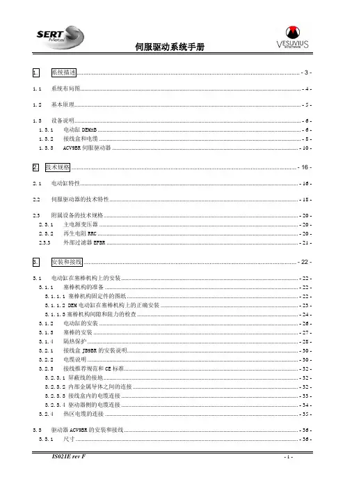
1.系统描述...................................................................................................................................- 3 -1.1系统布局图.......................................................................................................................................................- 4 -1.2基本原理...........................................................................................................................................................- 5 -1.3设备说明...........................................................................................................................................................- 6 -1.3.1电动缸DEMxB...........................................................................................................................................- 6 -1.3.2接线盒和电缆..........................................................................................................................................- 8 -1.3.3ACV9BR伺服驱动器...............................................................................................................................- 10 -2.技术规格....................................................................................................................................- 16 -2.1电动缸特性.....................................................................................................................................................- 16 -2.2伺服驱动器的技术特性.................................................................................................................................- 18 -2.3附属设备的技术规格.....................................................................................................................................- 20 -2.3.1主电源变压器........................................................................................................................................- 20 -2.3.2再生电阻RRC.........................................................................................................................................- 20 -2.3.3外部过滤器EFBR...................................................................................................................................- 21 -3.安装和接线.............................................................................................................................- 22 -3.1电动缸在塞棒机构上的安装.........................................................................................................................- 22 -3.1.1塞棒机构的准备....................................................................................................................................- 22 -3.1.1.1 塞棒机构固定件的图纸.....................................................................................................................- 22 -3.1.1.2 DEM电动缸在塞棒机构上的正确安装..............................................................................................- 23 -3.1.1.3塞棒机构间隙和阻力的检查..............................................................................................................- 24 -3.1.2电动缸的安装........................................................................................................................................- 26 -3.1.3塞棒的安装............................................................................................................................................- 27 -3.1.4隔热保护................................................................................................................................................- 28 -3.2.1接线盒JB9BR的安装说明.....................................................................................................................- 30 -3.2.2电缆说明................................................................................................................................................- 30 -3.2.3接线推荐规范和CE标准.......................................................................................................................- 32 -3.2.3.1 屏蔽线的接地.....................................................................................................................................- 32 -3.2.3.2 内部金属导体之间的连接.................................................................................................................- 32 -3.2.3.3 接线盒内的电缆连接.........................................................................................................................- 33 -3.2.3.4 驱动器侧的电缆连接.........................................................................................................................- 34 -3.2.4热区电缆的连接....................................................................................................................................- 35 -3.3驱动器ACV9BR的安装和接线.......................................................................................................................- 36 -3.3.1尺寸........................................................................................................................................................- 36 -3.3.2安装、定位和冷却................................................................................................................................- 37 -3.3.3电源的连接............................................................................................................................................- 39 -4.操作........................................................................................................................................- 40 -4.1手动模式.........................................................................................................................................................- 40 -4.2远程工作模式.................................................................................................................................................- 41 -4.3自动模式.........................................................................................................................................................- 41 -4.4塞棒关闭和安全装置.....................................................................................................................................- 42 -4.4.1塞棒关闭................................................................................................................................................- 42 -4.4.2断开电机电源(可选项).....................................................................................................................- 42 -4.5运行故障的处理.............................................................................................................................................- 43 -5.维护........................................................................................................................................- 44 -5.1检查周期.........................................................................................................................................................- 44 -5.2电动缸的检查和维护.....................................................................................................................................- 45 -5.3推荐的备件.....................................................................................................................................................- 49 -5.4伺服驱动器的故障代码.................................................................................................................................- 53 -5.5故障的数字输出代码.....................................................................................................................................- 57 -5.6驱动器复位和状态显示.................................................................................................................................- 58 -5.7没有报警显示时的故障排除.........................................................................................................................- 59 -6.辅助设备.................................................................................................................................- 61 -6.1DEM系列电动缸的测试台..............................................................................................................................- 61 -6.2塞棒机构MQS..................................................................................................................................................- 61 -1.系统描述SERT的塞棒执行器系统用于控制塞棒和塞棒机构的位置,以控制流入结晶器的钢水的流量。
伺服控制器调试说明伺服控制器调试前必须做好以下两项准备工作:1.将静叶置手动状态,使用电磁阀关闭静叶,现场观测静叶应该向关小的方向动作。
静叶关到最小时,位置传感器的反馈电流应为4mA左右(不要求是准确的4mA)。
2.将静叶置手动状态,使用电磁阀开启静叶,现场观测静叶应该向开大的方向动作。
静叶开到最大时,位置传感器的反馈电流应为20mA左右(不要求是准确的20mA)。
开始调试:1.将静叶置手动状态,使用电磁阀完全关闭静叶,按手操器F1键,此时手操器屏幕上有“确定传感器新零点”字样,按回车键确认。
2.将静叶置手动状态,使用电磁阀完全开启静叶,按手操器F2键,此时手操器屏幕上有“确定传感器新量程”字样,按回车键确认。
3.同时按下手操器shift和F1键即F5键,此时手操器屏幕上有“设定K值”字样。
设置K值为1.0000。
此时将静叶置手动状态,使用伺服阀控制静叶,在静叶开度设置框中打入不同数字,现场观测静叶应该可以动作。
如果静叶不动作,请将K值设定为-1.0000。
K 值只能为1.0000或-1.0000。
更改K值先同时按shift和F1,再按回车键,此时K值的末位数字闪烁,按下shift不放同时按上下键可以将光标左右移动。
单按上下键可以改变光标所在位的数字。
4.将静叶置手动状态,使用伺服阀控制静叶,在静叶开度设置框中打入0.0,现场观测静叶应该关到最小。
此时按下F3键,此时手操器屏幕上有“确定指示电流新零点”字样,按回车键,更改此值为6400.0,按回车键确认。
通过增加或减小指示电流零点的值使电脑中显示静叶开度为0.0~0.5%。
5.将静叶置手动状态,使用伺服阀控制静叶,在静叶开度设置框中打入100.0,现场观测静叶应该开到最大。
此时按下F4键,此时手操器屏幕上有“确定指示电流新量程”字样,按回车键,更改此值为32000.0,按回车键确认。
通过增加或减小指示电流量程的值使电脑中显示静叶开度为99.5~100.0%。
嵌入式数控交流伺服系统使用说明书·在使用本产品之前,请先阅读《产品说明书》及所搭配的缝纫机机械说明书。
·本产品必须由接受过专业培训的人员来安装或操作。
·请尽量远离电弧焊接设备,以免产生的电磁波干扰本控制器而发生误动作。
·请不要在室温45°以上或者0°以下的场所使用。
·请不要在湿度30%以下或者95%以上或者有露水和酸雾的场所使用。
·安装控制箱及其他部件时,请先关闭电源并拔掉电源插头。
·为防止干扰或漏电事故,请做好接地工程,电源线的接地线必须以牢固的方式与大地有效连接。
·所有维修用的零部件,须由本公司提供或认可,方可使用。
·在进行任何保养维修动作前,必须关闭电源并拔掉电源插头。
控制箱里有高压危险,必须关闭电源五分钟后方可打开控制箱。
·本手册中标有 符号之处为安全注意点,必须注意并严格遵守,以免造成不必要的损害。
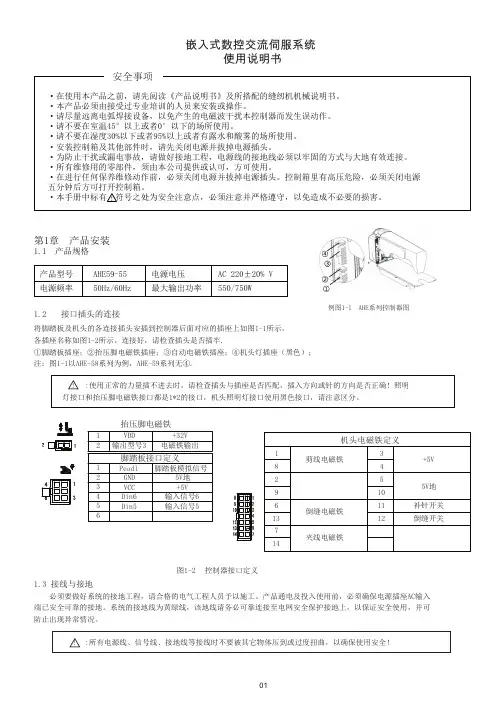
安全事项第1章 产品安装1.1 产品规格产品型号AHE59-55电源电压AC 220±20% V 50Hz/60Hz最大输出功率550/750W电源频率将脚踏板及机头的各连接插头安插到控制器后面对应的插座上如图1-1所示,各插座名称如图1-2所示。
连接好,请检查插头是否插牢. ①脚踏板插座;②抬压脚电磁铁插座;③自动电磁铁插座;④机头灯插座(黑色); 注:图1-1以AHE-58系列为例,AHE-59系列无④.1.2 接口插头的连接例图1-1 AHE 系列控制器图图1-2 控制器接口定义1.3 接线与接地必须要做好系统的接地工程,请合格的电气工程人员予以施工。
产品通电及投入使用前,必须确保电源插座AC 输入端已安全可靠的接地。
系统的接地线为黄绿线,该地线请务必可靠连接至电网安全保护接地上,以保证安全使用,并可防止出现异常情况。
:所有电源线、信号线、接地线等接线时不要被其它物体压到或过度扭曲,以确保使用安全!!抬压脚电磁铁12123456VDD 输出型号3+32V 电磁铁输出Peadl GND VCC Din6Din5脚踏板接口定义脚踏板模拟信号5V 地+5V 输入信号6输入信号5机头电磁铁定义1829613714345101112剪线电磁铁倒缝电磁铁夹线电磁铁+5V5V 地补针开关倒缝开关!第2章 操作面板使用说明2.1操作面板的显示说明2.2按键功能介绍功能描述序号外观名称长按恢复厂家出厂参数。

MMT-直流伺服驱动器使用手册济南科亚电子科技有限公司直流伺服驱动器使用说明书一、概述:该伺服驱动器采用全方位保护设计,具有高效率传动性能:控制精度高、线形度好、运行平稳、可靠、响应时间快、采用全隔离方式控制等特点,尤其在低转速运行下有较高的扭矩及良好的性能,在某些场合下和交流无刷伺服相比更能显示其优异的特性,并广泛应用于各种传动机械设备上。
二、产品特征:◇PWM控制H桥驱动◇四象限工作模式◇全隔离方式设计◇线形度好、控制精度高◇零点漂移极小◇转速闭环反馈电压等级可选◇标准信号接口输入0--±10V◇开关量换向功能◇零信号时马达锁定功能◇上/下限位保护功能◇使能控制功能◇上/下限速度设定◇输出电流设定功能◇具有过压、过流、过温、输出短路、马达过温、反馈异常等保护及报警功能三、主要技术参数◇控制电源电压AC:110系列:AC :110V±10%220系列:AC :220V±10%◇主电源电压AC:110系列:AC 40----110V220系列:AC50---- 220V◇输出电压DC:110系列:0—130V或其它电压可设定220系列:0—230V或其它电压可设定◇额定输出电流:DC 5A(最大输出电流10A)DC 10A(最大输出电流15A)DC 20A(最大输出电流25A)◇控制精度:0.1%◇输入给定信号:0—±10V◇测速反馈电压:7V/1000R 9.5V/1000R13.5V/1000R 20V/1000R可经由PC板内插片选定并可接受其它规格订制四、安装环境要求:◇环境温度:-5ºC ~ +50ºC◇环境湿度:相对湿度≤80RH。
(无结露)◇避免有腐蚀气体及可燃性气体环境下使用◇避免有粉尘、可导电粉沫较多的场合◇避免水、油及其他液体进入驱动器内部◇避免震动或撞击的场合使用◇避免通风不良的场合使用五、电源输入说明该驱动系统分两路电源输入:即U1、V1为主电源输入,U2、V2为控制电表1注:1、驱动器的主电源(即U1 V1)独立供电时,若电源开路时,驱动器会报警(面板上的T.F灯亮)待故障排出后,驱动器自动回复正常。
伺服放大器使用说明书一、概述伺服放大器是自动控制系统中的一个重要组成单元,和电动执行机构配套,组成比例式电动控制机构,可广泛用于电力、冶金、化工、轻工等工业部门的自动控制系统中。
它可与DDZ-S系列电动执行机构配套,也可作为一个通用单元,应用在其它类型的电动执行机构上。
与其它类型的伺服放大器比较,有如下特点:1.电路采用智能控制系统对输入电流与反馈电流进行采样、比较,依据它们的差值大小对电机进行正反转控制。
2.系统对死区和精度进行自动调节,使控制品质最优。
3.也可手动调节死区大小以适应现场实际要求。
4.具有输入信号断路或小于一定值、位置反馈信号断路或小于一定值、反馈信号不跟随或反向变化大于一定值或固态继电器输出短路时,系统自动保护防止执行机构动作错误的功能以及开路报警、断电抱闸等功能。
二、主要技术指标1.输入信号:4~20mA2.阀位反馈输入信号:4~20mA3.输入通道:2个4.输入阻抗:250Ω5.输出功率:220VAC5A6.最大误差:2.5%7.报警输出:无源接点1常开1常闭8.工作电压:220VAC50Hz9.工作条件:环境温度0~50℃相对湿度〈85%三、接线端子图2-b9 电流输入+2-a9 电流输入-2-b11 阀位反馈输入+2-a11 阀位反馈输入-2-b3 故障状态信号输出端常闭点2-b4 常开点2-b5 公共点1-b13 接大地1-a8 火线1-a7.10 零线1-a5 接电机正转线圈1-b3 接电机反转线圈1-b8 接抱闸线圈注意: 电机接线要分清正反,正转时阀门开大,反转时阀门关小,并且阀门开度要与位返电流变化方向一致。
四、仪表的调试仪表功能性测试用两路信号源作输入信号,三个220V灯泡作负载, 2-b9 2-a9 输入一路4~20mA信号2-b11 2-a11 输入另一路4~20mA信号1-a5 1-a7 接一灯泡定义为D11-b3 1-a7 接一灯泡定义为D21-b8 1-a7 接一灯泡定义为D3正确接线后通电1、当输入电流IN大于反馈电流WF时D1灯亮2、当输入电流IN等于反馈电流WF时灯不亮3、当输入电流IN小于反馈电流WF时D2灯亮4、当输入电流IN或反馈电流WF的值小于3.5mA或断路时面板上黄灯亮,同时系统切断总电源并且送出抱闸信号(D3灭)和报警信号(常闭接点断开)。

Panasonic松下数字交流伺服 安装调试说明书 (2003.11版本) 目 录 1. 松下连接示意图 2. 通电前的检查 3. 通电时的检查 4. 松下伺服驱动器的参数设定 5. 松下伺服驱动器的参数和性能优化调整 1. 松下连接示意图 重要提示: 由于电机和编码器是同轴连接,因此,在电机轴端安装带轮或连轴器时,请勿敲击。
否则,会损坏编码器。
(此种 情况,不在松下的保修范围!) 2. 通电前的检查 1) 确认松下伺服驱动器和电机插头的连接,相序是否正确: A.中惯量电机,不带刹车制动器的连接: 伺服驱动器 电机插头 U A V B W C 接地 D 注: 电机相序错误,通电时会发生电机抖动现象。
B.中惯量电机MDMA 0.75KW-2.5KW,带刹车制动器电机的连接: 伺服驱动器 电机插头 U F V I W B 接地 D 刹车电源 G 刹车电源 H C. 中惯量电机MDMA 3KW-5KW,带刹车制动器电机的连接: 伺服驱动器 电机插头 U D V E W F 接地 G 刹车电源 A 刹车电源 B 2)确认松下伺服驱动器CN SIG和松下伺服电机编码器联接正确, 接插件螺丝拧紧。
3)确认松下伺服驱动器CN I/F和数控系统的插头联接正确, 接插件螺丝拧紧。
3.通电时的检查 1) 确认三相主电路输入电压在200V-220V范围内。
建议用户选用380V/200V的三相伺服变压器。
2)确认单相辅助电路输入电压在200V-220V范围内。
4.松下伺服驱动器的参数设定 1)松下伺服驱动器修改参数的操作方法 A. 接通驱动器电源; B. 按操作面板上的“SET”键; C. 按住“MODE”键,选择参数页面 PR _ 00 ; D. 用上○∧,下○∨按钮,选择你需要修改参数的参数号码 PR _ 42 (例修改42号参数); E. 按“SET”键,显示原来的参数值 00; F. 用左○<,上○∧,下○∨按钮,改变参数值; G. 修改完毕, 按“SET”键确定。
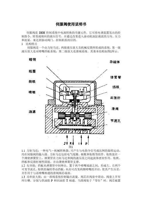
伺服阀使用说明书伺服阀是DEH控制系统中电液转换的关键元件,它可将电调装置发出的控制指令,转变成相应的液压信号,并通过改变进入油动机油缸液流的方向、压力和流量,来达到驱动阀门、控制机组的目的。
1 结构特点伺服阀是一个由力矩马达、两级液压放大及机械反馈所组成的系统。
第一级液压放大是双喷嘴挡板系统;第二级放大是滑阀系统。
其基本结构如图1所示。
图11.1 力矩马达:一种电气—机械转换器,可产生与电指令信号成比例的旋转运动,用在伺服阀的输入级。
力矩马达包括电气线圈、极靴和衔铁等组件。
衔铁装在一个薄壁弹簧管上,弹簧管在力矩马达和阀的液压段之间起流体密封作用。
衔铁、挡板和反馈杆刚性固接,并由薄壁弹簧管支撑。
1.2 先导级:挡板从弹簧管中间伸出,置于两个喷嘴端面之间,形成左、右两个可变节流孔。
衔铁的偏转带动挡板,从而可改变两侧喷嘴的开启,使其产生压差,并作用于与该喷嘴相通的滑阀阀芯端部。
1.3 功率放大级:由一滑阀系统控制输出流量。
阀芯在阀套中滑动,阀套上开有环行槽,分别与供油腔P和回油腔T相通。
当滑阀处于“零位”时,阀芯被置于阀套的中位;阀芯上的凸肩恰好将进油口和回油口遮盖住。
当阀芯受力偏离“零位”向任一侧运动时,导致油液从供油腔P流入一控制腔(A或B),从另一控制腔(B或A)流入回油腔T。
阀芯推动反馈杆端部的小球,产生反馈力矩作用在衔铁挡板组件上。
当反馈力矩逐渐等于电磁力矩时,衔铁挡板组件被移回到对中的位置。
于是,阀芯停留在某一位置。
在该位置上,反馈力矩等于输入控制电流产生的电磁力矩,因此,阀芯位置与输入控制电流的大小成正比。
1.4 特点:●衔铁及挡板均工作在中立位置附近,线性好●喷嘴挡板级输出驱动力大●阀芯基本处于浮动状态,不易卡住●阀的性能不受伺服阀中间参数的影响,阀的性能稳定,抗干扰能力强,零点漂移小2 工作原理:当力矩马达没有电信号输入时,衔铁位于极靴气隙中间,平衡永久磁铁的磁性力。
当有欲使调节阀动作的电气信号由伺服放大器输入时,力矩马达的线圈中有电流通过,产生一磁场,在磁场作用下,产生偏转力矩,使衔铁旋转,同时带动与之相连的挡板转动,此挡板伸到两个喷嘴中间。
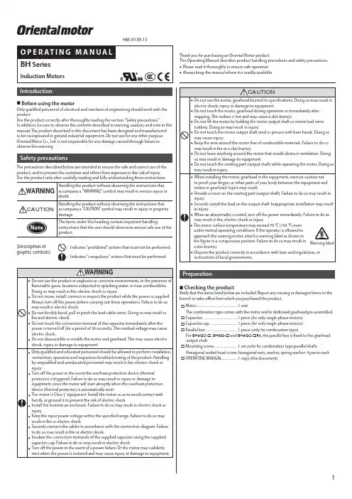
IntroductionBefore using the motorOnly qualified personnel of electrical and mechanical engineering should work with the product.Use the product correctly after thoroughly reading the section "Safety precautions."In addition, be sure to observe the contents described in warning, caution, and note in this manual. The product described in this document has been designed and manufacturedto be incorporated in general industrial equipment. Do not use for any other purpose. Oriental Motor Co., Ltd. is not responsible for any damage caused through failure to observe this warning.Safety precautionsThe precautions described below are intended to ensure the safe and correct use of the product, and to prevent the customer and others from exposure to the risk of injury.[Description of graphic symbols] :Indicates "prohibited" actions that must not be performed. :Indicates "compulsory" actions that must be performed.PreparationChecking the productVerify that the items listed below are included. Report any missing or damaged items to thebranch or sales office from which you purchased the product.☐ Motor ................................................1 unitThe combination type comes with the motor and its dedicated gearhead pre-assembled.☐ Capacitor .........................................1 piece (for only single-phase motors)☐ Capacitor cap .................................1 piece (for only single-phase motors)☐ Parallel key ......................................1 piece (only for combination type)For BH6G2-☐, BH8G-☐ and BH6G2-☐RA, the parallel key is fixed to the gearheadoutput shaft.☐ Mounting screw ............................1 set (only for combination type parallel shaft)Hexagonal socket head screw, hexagonal nuts, washer, spring washer: 4 pieces each☐ OPERATING MANUAL ..................1 copy (this document)HM-9139-13Thank you for purchasing an Oriental Motor product.This Operating Manual describes product handling procedures and safety precautions.•Please read it thoroughly to ensure safe operation.•Always keep the manual where it is readily available.Checking the model nameThis operation manual covers the following products. Make sure that the product is the one you ordered and is listed below by checking the model number listed on the nameplate. Verify that the voltage and output listed on the nameplate are appropriate for your application and that the correct value capacitor has been provided.Enter the number representing the gear ratio of the gearhead in the box ☐ within themodel name.BHI62AT-A BHI62C-A BHI62CT-A BHI62E-A BHI62ET-A BHI62F-A BHI62FT-A BHI62S-A BHI62ST-A BHI62U-A BHI62UT2-AInstallationLocation for installationInstall the motor and capacitor in a location that meets the following conditions.Using the motor and capacitor in a location that does not satisfy these conditions could damage them. •Indoors•Ambient temperature: –10 °C to +40 °C [+14 °F to +104 °F] (non-freezing) (–10 °C to +50 °C [+14 °F to +122 °F] for 100/200 VAC) (non-freezing) •Ambient humidity: 85% or less (non-condensing)•Not exposed to explosive, flammable, or corrosive gases •Not exposed to direct sunlight •Not exposed to dust•Not exposed to water or oil•A place where heat can escape easily•Not exposed to continuous vibration or excessive impact •1,000 meters or less above sea levelto cause a secondary damage. Grease leakage may lead to problems in the customer's equipment or products.z Combination type: parallel shaft gearheadSecure the motor with mounting screw set (supplied) through the four mounting holes provided. (Mounting plate thickness is 10 mm (0.39 in.) when using the supplied mounting screws.)zCombination type: right-angle shaft gearheadSecure the motor with screws (notsupplied) through the four mounting holes provided. Do not leave a gap between themotor and mounting plate.in damage to the gearhead internal bearings.•The diameter of the boss of the shaft is Ø58h8, use it as a guide for proper alignment.Removing and assembling the gearheadSee the following steps to replace the gearhead or to change the outlet position of the lead wires and the position of the terminal box.Removing the gearhead from the motorRemove the hexagonal socket head screws (2 places or 4 places) assembling the motor and gearhead and detach the motor from the gearhead.Hexagonal socket head screwAssembling the gearhead to the motor1. Keep the pilot sections of the motor andgearhead in parallel, and assemble the gearhead with the motor while slowly rotating it clockwise/counterclockwise. At this time, note so that the pinion of the motor output shaft does not hit the side panel or gears of the gearhead strongly.2. Check that there is no gap between themotor and gearhead, and tighten them with hexagonal socket head screws (2 pieces or4 pieces).Assemble the gearhead to the motor in a condition where the motor output shaft is in an upward direction.shorter service life.•Do not allow dust to attach to the pilot sections of the motor and gearhead. Also, assemble the motor and gearhead carefully by not pinching theO-ring at the motor pilot section. If the O-ring is crushed or severed, grease may leak from the gearhead.zRround shaft typeSecure the motor with hexagonal socket head screws (not supplied) through the four mounting holes provided. Do not leave a gap between the motor and mounting plate.z Motor with cooling fanWhen installing a motor with cooling fan onto a device, leave 10 mm (0.39 in.) or more behind the fan cover or open a ventilation hole so that the cooling inlet on the back of the motor cover is not blocked.Mounting the capacitor (only for single-phase motors)Before mounting the provided capacitor, check that the capacitor’s capacitance matches that stated on the motor’s nameplate.Mount the capacitor securely by using M4 screws (not provided).Ø4.3 mm(Ø0.169 in.)closer, the life of the capacitor will be shortened.reduced by adding a frictional load.z Combination type: parallel shaft gearhead,Combination type: right-angle shaft (solid shaft) gearheadThe gearhead shaft is provided with a key slot for connecting the transmission parts. Whenconnecting the transmission parts, ensure that theshaft and parts have a clearance fit, and always fix the parallel key to the output shaft with a screw toprevent the parts from rattling or spinning.When using the output shaft end tapped hole of a gearheadUse a tapped hole [M6, Effective depth 12 mm (0.47 in.)] provided at the end of the output shaft of BH6G2-☐ and BH6G2-☐RA as an auxiliary means for preventing the transfer mechanism from disengaging.z Combination type: right-angle shaft (hollow shaft) gearheadMounting method of the load varies depending on the load shaft conditions. See the following figures.The hollow output shaft inside dimension is processed to a tolerance of H8, and incorporates a key slot for load shaft attachment. A load shaft tolerance of h7 isrecommended. Also, apply anti-seizing agent such as molybdenum disulfide grease on the surface of the load shaft and the bore of the hollow output shaft.After attaching the load, attach the safety cover.[Unit: mm (in.)]••Stepped load shaft••Non-stepped load shaftConnectionInsulate all the wire connections such as the connecting part between the motor lead wires and the power supply.Be sure to ground the product using the Protective Earth Terminal on the motor.stress.z•terminal box.On the BHI62ST-A , refer to the following specifications.Applicable crimp terminal: Insulated round crimp terminal Terminal screw size: M4Tightening torque: 1.0 to 1.3 N·m (8.8 to 11.5 lb-in)Applicable lead wire: AWG18 (0.75 mm 2) or thickers s[Unit: mm (in.)] •For wiring, be sure to use cable (not provided) that meets the following specifications.Applicable cable diameter: Ø6 to Ø12 mm (Ø0.236 to Ø0.472 in.) Applicable lead wire: AWG24 to 12 (0.2 to 3.5 mm 2) Length of strip is 8 mm (0.31 in.) •When sealing the terminal box cover, ensure that no scraps or particles get caught between the contact surfaces.•The terminal cover mounting screws are specifically designed for mounting the terminal cover. They are provided with a rubber seal and flat washer that keep the terminal box dust-resistant and splashproof.In order to maintain a tight seal around the terminal box, use only the provided screws. Also, this terminal box is constructed to hold a gasket. If this gasket comes out of the box, please reseal it correctly on the box.Also refer to the tightening torque table (below) to determine the appropriate tightening torque to use when fastening the terminal cover and cable gland.Terminal cover 0.3 to 0.4 N·m (42 to 56 oz-in)Cable gand 2.5 to 3.8 N·m (350 to 530 oz-in)Cable clamp 0.2 to 0.3 N·m (28 to 42 oz-in)Terminal block0.5 to 0.8 N·m (71 to 113 oz-in)Changing the cable outlet positionThe cable outlet can be oriented and fixed in three different directions by changing the mounting direction of the terminal box. Follow the procedure below:1. Loosen the terminal cover mounting screws (M4×3 pieces) and remove the terminal coverand sheet gasket from the terminal box.2. Loosen the terminal box mounting screws (M4×4 pieces) and remove the terminal box from the terminal block base.3. Turn the cable outlet on the terminal box clockwise or counterclockwise by 90° at atime from the factory-set position.4. Install the terminal box onto the terminal block base.5. Install the sheet gasket and terminal cover onto the terminal box.•A gasket is installed between the terminal box and terminal block base. Don’t forget to assemble the gasket. When assembling the parts, also be careful not to let any foreign object enter between the terminal box and terminal block base. •Refer to the aforementioned table for the screw tightening torque.z Layout of terminalsSingle-phase type4 terminals Terminal blockCable clamp Z2U2U1Three -phase type[ Combination type ]• 200 VAC/220 VAC/230 VAC motors•[ Round shaft type ]Connecting Protective Earth Terminal (cable type)Insulated round crimp terminal Terminal screw size: M4Tightening torque: 1.0 to 1.3 N·m (8.8 to 11.5 lb-in)Applicable lead wire: AWG18 (0.75 mm 2) or thicker[Unit: mm (in.)]9s sz Three-phase 380 VAC/400 VAC/415 VAC motorsConnect the motor to a terminal box by following the procedure below:1. Loosen the terminal cover mounting screws (M4×3 pieces) and remove the terminal coverand sheet gasket from the terminal box.2. Pass the cable through the cable gland and connect the lead wires to the terminal block.Connect the lead wire for grounding to the Protective Earth Terminal.3.Install the sheet gasket and terminal cover on the terminal box.The terminal box can be removed. Loosen the terminal box mounting screws (M4×4 pieces)and take out the terminal box.•terminal box.•Use a cable (not supplied) of the following specifications:Applicable cable diameter: Ø6 to Ø12 mm (Ø0.236 to 0.472 in.) Applicable lead wire: AWG20 (0.5 mm 2) or thicker•When connecting the cable on the terminal block, use the following crimp terminal.Insulated round crimp terminals s[Unit: mm (in.)]•Don’t forget to assemble the sheet gasket between terminal box and terminal cover. When assembling the parts, also be careful not to let any foreign object enter between the terminal cover and terminal box.•Refer to the table below to determine the appropriate tightening torque to use when fastening the terminal cover and cable gland.Terminal cover 0.3 to 1.0 N·m (42 to 142 oz-in)Terminal box1.0 to 1.5 N·m (142 to 210 oz-in)Cable gland (Tightening nut)2.0 to 2.5 N·m (280 to 350 oz-in)Cable gland (Nipple) 2.0 to3.75 N·m (280 to 530 oz-in)Terminal block1.0 to 1.2 N·m (142 to 170 oz-in)Protective Earth Terminal1.0 to 1.5 N·m (142 to 210 oz-in)Connection diagramThe direction of rotation is as viewed from the side of the motor’s output shaft.“CW” indicates clockwise and “CCW” counterclockwise. The gearhead’s output shaft may, depending on the gear ratio, turn in the opposite direction of the motor shaft.Check the rotation direction before connecting.z Single-phase motor*1•A , C , E , F appear at the position in the model number indicated by the box (☐).Enter T (terminal box) in the box ( ) within the model name.*2•Colors shown in the connection diagram indicate the colors of lead wires and Z2, U2,and U1 indicate terminal codes inside the terminal box.••Capacitor connection (only for single-phase motors)When crimp terminals are used, use the FASTON terminals 187 Series (TE Connectivity).Use the supplied capacitor cap to insulate the capacitorterminal connection.The capacitor has fourterminals that are internally connected as shown in thefigure.<Capacitor internal wiring diagram>187 Series z Three -phase motor*1•S , U appear at the position in the model number indicated by the box (☐).Enter T or T2 (terminal box) in the box ( ) within the model name.*2•Colors shown in the connection diagram indicate the colors of lead wires and U, V, andW indicate terminal codes inside the terminal box.••For protection of contact (switch)If the switch is used for starting/stopping the motor or switching the rotation direction, R 0=5 to 200 ΩC 0=0.1 to 0.2 µF 250 VAC EPCR1201-2OperationThe motor rotates when the power supply is turned on.For protection against electric shock, do not turn on the power supply until the wiring is complete.can be measured by fastening a thermometer to the motor’s surface, or with thermo-tape.•Bring single-phase motors to a complete stop before switching thedirection of rotation. If you try to switch the direction of rotation before the motor has stopped, it may not change or may require time.•Use the provided capacitor for single-phase motors and always keep the capacitor connected after the motor is started. •The three-phase 380/400/415 VAC motors cannot be combined with an inverter. If combined with an inverter, these motors may be damaged due to deteriorated insulation of the motor coil.Time ratingThis motor can be operated continuously (continuous rating).•Unauthorized reproduction or copying of all or part of this manual is prohibited. •Oriental Motor shall not be liable whatsoever for any problems relating to industrial property rights arising from use of any information, circuit, equipment or device provided or referenced in this manual.•Characteristics, specifications and dimensions are subject to change without notice. •While we make every effort to offer accurate information in the manual, we welcome your input. Should you find unclear descriptions, errors or omissions, please contact the nearest office.•is a registered trademark or trademark of Oriental Motor Co., Ltd., in Japan and other countries.© Copyright ORIENTAL MOTOR CO., LTD. 2011Published in March 2020Technical Support Tel:(800)468-39828:30 A.M. to 5:00 P .M., P .S.T. (M-F)7:30 A.M. to 5:00 P .M., C.S.T. (M-F) Schiessstraße 44, 40549 Düsseldorf, Germany Technical Support Tel:00 800/22 55 66 22www.orientalmotor.de Tel:01256-347090 Tel:01 47 86 97 50www.orientalmotor.fr Tel:02-93906346www.orientalmotor.itTel:+55-11-3266-6018.br• Please contact your nearest Oriental Motor o ce for further information.4-8-1Higashiueno,Taito-ku,Tokyo 110-8536 JapanTel:03-6744-0361www.orientalmotor.co.jpTel:0800-060708 SingaporeTel:1800-8420280.sg Tel:1800-806161.my KoreaTel:080-777-2042www.inaom.co.kr Tel:1800-888-881www.orientalmotor.co.th Tel:400-820-6516 Tel:+91-80-41125586www.orientalmotor.co.in Hong Kong BranchTel:+852-2427-9800This motor is equipped with a feature listed below to prevent the motor from burning out as a result of abnormal heating which may be caused by misapplication.Thermal protection (“THERMALLY PROTECTED” is stamped on the motor nameplate)When the motor reaches a predetermined temperature, the internal thermal protector is activated and the motor is stopped.With the automatic resume feature, the motor automatically begins operating again as soon as the motor temperature falls.Always turn the power off before performing inspections.Thermal protector activation range:Power is turned off at 150 °C±5 °C (302 °F±9 °F) [130 °C±5 °C (266 °F±9 °F)]*Power is turned back on at 96 °C±15 °C (205 °F±27 °F) [83 °C±15 °C (181 °F±27 °F)]* *[ ] indicates the value for the three-phase 380/400/415 VAC motors.When the motor is not functioning normally, perform an inspection covering the points listed in the table bellow.If the inspection shows that everything is normal but the motor and control unit still are not functioning correctly, contact the nearest ORIENTAL MOTOR office.Specifications/ General specificationsCheck on the Oriental Motor Website for the product specifications.Regulations and standardsUL Standards, CSA Standards, CCC SystemThis product is recognized by UL under the UL and CSA Standards, and also certified by CQC under the China Compulsory Certification (CCC) system.The motor model name represents the model that conforms to the standards.The three-phase 380/400/415 VAC motors have obtained only the certification under the CCC system.• z Standards for accessoriesCapacitor: UL File No.E83671 (CYWT2)Capacitor cap: UL File No.E56078 (YDTU2)CE MarkingThis product is affixed the CE Marking under the Low Voltage Directive.z Low Voltage Directive Applicable standardsEN 60034-1, EN 60034-5, EN 60664-1, EN 60950-1Installation conditions (For EN standard)•Overvoltage category:Ⅱ •Pollution degree: 2•Protection against electric shock: Class ⅠequipmentWhen the machinery to which the motor is mounted requires overvoltage category Ⅲand pollution degree 3 specifications, install the motor in a cabinet that comply with IP54 and connect to power supply via an isolation transformer.The motor with a terminal box requires overvoltage category Ⅲ* and pollution degree 3 specifications (except for the motor installation surface of the round shaft type). *If EN 60950-1 is required, Overvoltage category is Ⅱ.z Motor temperature rise testsTemperature rise tests required by the above standards are performed in a state that has been attached a gearhead or a heat radiation plate.The size and material for the heat radiation plates are as follows.Electrical appliance and material safety lawBHI62ST-A bears amark.RoHS DirectiveThe products do not contain the substances exceeding the restriction values of RoHS Directive (2011/65/EU).。
版权声明北京和利时电机技术有限公司保留所有权力说明书的内容参照了相关法律基准和行业基准。
使用产品时,如对本说明书提供的内容有疑问,请向购买产品的销售人员咨询,或致电客户服务热线,或致信本公司邮箱。
由于产品的不断更新升级,和利时电机保留在不事先通知的情况下,修改本手册中的产品和产品规格参数等文件的权利,提示客户请使用最新版本的说明书。
和利时电机具有本产品及其软件的专利权、版权和其它知识产权。
未经许可,不得直接或者间接地复制、制造、加工、使用本产品及其相关部分。
和利时电机具有本说明书的著作权,未经许可,不得修改、复制说明书的全部或部分内容。
版本号 07/2015目录产品概要产品特性 (1)型号命名 (1)产品组成 (1)产品铭牌 (2)技术特性 (2)外形尺寸及重量 (4)安装和接线使用和储运环境 (6)安装注意事项 (6)电源端子-接线与配线 (7)编码器反馈连接器CN3 -接线与配线 (8)电机绕组-接线与配线 (8)接线与配线示意图 (9)输入输出连接器CN2 -接线与配线 (10)通讯连接器CN1 -接线与配线 (15)试运行和操作通电前注意事项 (16)操作和显示 (16)运行设定操作流程JOG试机运行 (20)内部速度模式运行 (21)外部速度模式运行 (22)位置模式运行 (22)转矩模式运行 (23)参数汇总说明参数分类描述 (24)控制参数修改要求 (24)D 状态监控参数 (24)F 控制参数 (25)运行和调整运行前检查 (32)增益调整 (32)故障和解决方法故障显示和解决方法对照表 (33)产品概要MSE 系列伺服驱动器以美国TI 公司最新的32位数字处理芯片(DSP )作为核心控制,采用了先进的全数字电机控制算法,完全以软件方式实现了电流环、速度环、位置环的闭环伺服控制,具备良好的鲁棒性和自适应能力,可配合多种规格的伺服电机,适应于需要快速响应的精密转速控制与定位控制的应用系统,如:数控机床、印刷机械、包装机械、造纸机械、塑料机械、纺织机械、工业机器人、自动化生产线等。
汇川伺服电机参数调试说明书
汇川IS620N总线型:
1、报警代码950:正极限报警。
2、报警代码952:负极限报警。
伺服驱动器H0B组,用于监视电机状态。
H0B-00:显示时间实际电机转速。
H0B-07:显示电机当前绝对位置。
驱动器面板上点动试运行:
参数:
H0815:惯量比。
H0903:在线惯量辨识模式。
0:关闭,1、缓慢变化识别,2、一般识别,3、快速识别。
H0901:刚性等级。
H0900:设为1时启用手动的H0901的刚性表,为0时自动识别设置。
H0202:改变电机旋转方向。
H0203:改变输出脉冲相位。
电子齿轮设置:
电子齿轮比B/A=编码器分辨率/H05-02。
H05-02设置为0时启动1组和2组的切换功能。
A5XY接口(可以自己调用模块的时候定义自己喜欢的接口)。
所示的端口。
最后电池接到总开关上面,作为总控制。
伺服板上面有8排接伺服的插针(都含有编号),用于同时连接8个伺服。
注意:伺服接法,根据调试文档的伺服编号,对应接上伺服板如下编号。
1号伺服接到伺服板编号1的排针上
2号伺服接到伺服板编号5的排针上
3号伺服接到伺服板编号2的排针上
4号伺服接到伺服板编号6的排针上
5号伺服接到伺服板编号3的排针上
新增模块,加了伺服调速板。
需要应用此模块。
SetServo_OneCH
图标:
说明:控制伺服角度
参数:3个
Which:选择控制接口。
Channel :选择伺服编号。
angle :设定伺服角度。
time :控制伺服速度,例如,40,就是用40时间走到所设定的角度,数值越大,伺服速度越慢,最大不超过5000。
注意:由于RCU断电之后,不能直接给信号给伺服板让伺服失电,会导致调试的时候很不方便,所以需要用总开关关掉,才能使伺服失电。
这样是需要加上总开关的原因。
前循迹卡接:A2XY
后循迹卡接:A1XY。