
Chenming-Hu-ch1-slides
- 格式:ppt
- 大小:1.89 MB
- 文档页数:31



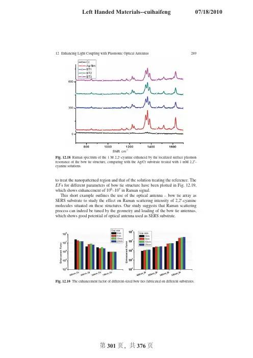
12Enhancing Light Coupling with Plasmonic Optical Antennas289Fig.12.18Raman spectrum of the1M2,2 -cyanine enhanced by the localized surface plasmon resonance of the bow tie structure,comparing with the Ag/Cr substrate treated with1mM2,2 -cyanine solutions.to treat the nanopatterned region and that of the solution treating the reference.The EF s for different parameters of bow tie structure have been plotted in Fig.12.19, which shows enhancement of106–107in Raman signal.This short example outlines the use of the optical antenna–bow tie array as SERS substrate to study the effect on Raman scattering intensity of2,2 -cyanine molecules situated on these structures.Our study suggests that Raman scattering process can indeed be tuned by the geometry and loading of the bow tie antennas, which shows good potential of optical antenna used as SERS substrate.Fig.12.19The enhancement factor of different-sized bow ties fabricated on different substrates.290Jun Xu,Anil Kumar,Pratik Chaturvedi,Keng H.Hsu and Nicholas X.Fang 12.5SummaryHarvesting and confining light using plasmonic nanoantennas represent an interest-ing frontier of metamaterial research.The convergence of RF and optical device designs will bring revolutionary changes in highly compact and integrated pho-tonics for photon energy conversion,adaptive sensing,and image processing.We expect many inspirations from RF metamaterial research to be transformed on the study of optical antennas and this could bring a profound impact to thefield of nanophotonics.Acknowledgments The authors are grateful for thefinancial supports from the Defense Advanced Research Projects Agency(grant HR0011-05-3-0002),Office of Naval Research(grant N00173-07-G013),and National Science Foundation(grant CMMI-0709023).Cathodoluminescence ex-periments were carried out in the Frederick Seitz Materials Research Laboratory Central Facilities, University of Illinois,which are partially supported by the U.S.Department of Energy under grants DE-FG02-07ER46453and DE-FG02-07ER46471.References1.Alu,A.,and Engheta,N.:Tuning the scattering response of optical nanoantennas with nanocir-cuit loads.Nat.Photon.2,307–310(2008)2.Alu,A.,and Engheta,N.:Input impedance,nanocircuit loading and radiation tuning of opticalnanoantennas.Phys.Rev.Lett.101,043901–043904(2008)3.Aroca,R.:Surface-enhanced Vibrational John Wiley&Sons Ltd,Chich-ester(2006)4.Bharadwaj,P.,and Novotny,L.:Spectral dependence of single moleculefluorescence enhance-ment.Opt.Express15,14266–14274(2007)5.Bohren,C.F.,and Huffman,D.R.:Absorption and Scattering of Light by Small Particles.Wiley,New York(1998)6.Bryant,G.W.,Abajo,F.J.G.,and Aizpurua,J.:Mapping the plasmon resonances of metallicnanoantennas.Nano Lett.8,631–636(2008)7.Chou,S.Y.,Krauss,P.R.,and Renstrom,P.J.:Nanoimprint lithography.J.Vac.Sci.Technol.B14,4129–4133(1996)8.Chou,S.Y.,Krauss,P.R.,Zhang,W.,Guo,L.,and Zhuang,L.:Sub-10nm imprint lithographyand applications.J.Vac.Sci.Technol.B15,2897–2904(1997)9.Crozier,K.B.,Sundaramurthy,A.,Kino,G.S.,and Quate,C.F.:Optical antennas:resonatorsfor localfield enhancement.J.Appl.Phys.94,4632–4642(2003)10.Cubukcu,E.,Kort,E.A.,Crozier,K.B.,and Cappaso,F.:Plasmonic laser antenna.Appl.Phys.Lett.89,093120–093123(2006)11.Draine,B.T.,and Flatau,P.J.:User guide for the Discrete Dipole Approximation CodeDDSCAT7.0./abs/0809.033712.Engheta,N.,Salandrino,A.,and Alu,A.:Circuit elements at optical frequencies:Nanoinduc-tors,nanocapacitors and nanoresistors.Phys.Rev.Lett.95,095504.4(2005)13.Farahani,J.N.,Eisler,H.J.,Pohl,D.W.,Pavius,M.,Fluckiger,P.,Gasser,P.,and Hecht,B.:Bow-tie optical antenna probes for single-emitter scanning near-field optical microscopy.Nan-otechnology18,125506(2007)14.Fleischmann,M.,Hendra,P.J.,and McQuillan,A.J.:Raman spectra of pyridine ad-sorbed ata silver electrode.Chem.Phys.Lett.26,163–166(1974)12Enhancing Light Coupling with Plasmonic Optical Antennas291 15.Fromm,D.P.,Sundaramurthy,A.,Schuck,P.J.,Kino,G.,and Moerner,W.E.:Gap-dependentoptical coupling of single bowtie nanoantennas resonant in the visible.Nano Lett.4,957–961 (2005)16.Garcia de Abajo,F.J.,and Howie,A.:Relativistic electron energy loss and electron-inducedphoton emission in inhomogeneous dielectrics.Phys.Rev.Lett.80,5180(1998)17.Garcia de Abajo,F.J.,and Kociak,M.:Probing the photonic local density of states with elec-tron energy loss spectroscopy.Phys.Rev.Lett.100,106804.4(2008)18.Grant,A.M.,and Creighton,J.A.:Anomalously intense Raman spectra of pyridine at a silverelectrode.J.Am.Chem.Soc.99,5215–5219(1977)19.Haes,A.J.,Haynes,C.L.,McFarland,A.D.,Schatz,G.C.,Van Duyne,R.R.,and Zou,S.L.:Plasmonic materials for surface-enhanced sensing and spectroscopy.MRS Bull.30,368–375 (2005)20.Hao,E.,and Schatz,G.C.:Electromagneticfields around silver nanoparticles and dimers.J.Chem.Phys.120,357–366(2004)21.Hewageegana,P.,and Stockman,M.I.:Plasmonic enhancing nanoantennas for photodetection.Infrared Phys.Tech.50,177–181(2007)22.Hsu,K.H.,Schultz,P.L.,Ferreira,P.M.,and Fang,N.X.:Electrochemical nanoim-printingwith solid-state superionic stamps.Nano Lett.7,446–451(2007)23.Ishi,T.,Fujikata,J.,Makita,K.,Baba,T.,and Ohashi,K.:Si nano-photodiode with a surfaceplasmon antenna.Japan.J.Appl.Phys.44,L364–L366(2005)24.Jeanmaire,D.L.,and Van Duyne,R.P.:Surface Raman electrochemistry part I.Heterocyclic,aromatic and aliphatic amines adsorbed on the anodized silver electrode.J.Electro Anal.Chem.84,1–20(1977)25.Kempa,K.,Rybczynski,J.,Huang,Z.,Gregorczyk,K.,Vidan,A.,Kimball,B.,Carl-son,J.,Benham,G.,Wang,Y.,Herczynski,A.,and Ren,Z.:Carbon nanotubes as optical antennae.Adv.Mater.19,421–426(2007)26.Kim,S.,Jin,J.H.,Kim,Y.J.,Park,I.Y.,Kim,Y.,and Kim,S.W.:High-harmonic gen-erationby resonant plasmonfield enhancement.Nature453,757–760(2008)27.M¨u hlschlegel,P.,Eisler,H.-J.,Martin,O.J.F.,Hecht,B.,and Pohl,D.W.:Resonant opticalantennas.Science308,1607–1609(2005)28.Mock,J.J.:Shape effects in plasmon resonance of individual colloidal silver nanopar-ticles.J.Chem.Phys.116,6755(2002)29.Novotny,L.:Effective wavelength scaling for optical antennas.Phys.Rev.Lett.98,266802–266804(2007)30.Palik,E.D.:Handbook of Optical Constants of Solids.Academic Press,Orlando,FL(1984)31.Schuck,P.J.,Fromm,D.P.,Sundaramurthy,A.,Kino,G.S.,and Moerner,W.E.:Im-provingthe mismatch between light and nanoscale objects with gold bowtie nanoantennas.Phys.Rev.Lett.94,017402–017404(2005)32.Schultz,P.L.,Hsu,K.H.,Fang,N.X.,and Ferreira,P.M.:Solid-state electrochemical nanoim-printing of copper.J.Vac.Sci.Technol.B25,2419–2424(2007)33.Shumaker-Parry,J.S.,Rochholz,H.,and Kreiter,M.:Fabrication of crescent-shaped opticalantennas.Adv.Mater.17,2131–2134(2005)34.Sivenpiper,D.et al.:High-impedance EM surfaces with a forbidden frequency band.IEEETrans.Micro.Theo.Tech.47,2059(1999)35.Tang,L.,and Miller,D.A.B.:C-shaped nanoaperture-enhanced Germanium photodetector.Opt.Lett.31,1519–1521(2006)36.Wang,Y.,Kempa,K.,Kimball,B.,Carlson J.B.,Benham,G.,Li,W.Z.,Kempa,T.,Rybczyn-ski,J.,Herczynski,A.,and Ren,Z.F.:Receiving and transmitting light-like ra-diowaves: antenna effect in arrays of aligned carbon nanotubes.Appl.Phys.Lett.85,2607–2609(2004)Chapter13Wideband and Low-Loss Metamaterialsfor Microwave and RF Applications:Fast Algorithm and Antenna DesignLe-Wei Li,Ya-Nan Li and Li HuAbstract In this chapter,a fast solver,i.e.,adaptive integral method(AIM)which is based on hybrid volume–surface integral equation,is utilized in the numerical sim-ulation of electromagnetic scattering from composite left-handed materials(LHM) such as split-ring resonators(SRR)with rods/wires.The volume electricfield inte-gral equation(EFIE)is applied to the dielectric region of this LHM,and the surface EFIE is applied on the conducting surface.The method of moments(MoM)is used to discretize the integral equation into a matrix solution and AIM is employed to reduce the memory requirement and CPU time for the matrix solution.Numeri-cal results and computational complexity analysis have shown that the AIM solver can significantly reduce the computational cost while maintaining a good accuracy. Inspired by the periodicity of SRR,the ASED-AIM,a new adaptive integral ap-proach based on accurate sub-entire-domain method,has been proposed to solve the electromagnetic scattering by large-scalefinite periodic arrays,especially the LHM structures like SRR.Several results are shown to demonstrate the efficiency of the method in solving periodic structures.Additionally,further computational time saving scheme for calculating the near-zone interaction matrix has been pro-posed.Both2-D and3-D periodic structures can be solved by this fast solver with impressive efficiency and accuracy.In the last section of this chapter,a novel rect-angular patch antenna was specifically designed using planar-patterned LHM con-cepts.This new antenna has demonstrated to have left-handed characteristics.It is shown to have great impact on the antenna performance enhancement in terms of the bandwidth significantly broadened and also in terms of high efficiency,low loss,and low VSWR.A good agreement is achieved between the simulation and measured results.This new antenna designed has strong radiation in the horizontal direction within the entire working band,which is desirable for some special applications. Joshua Le-Wei Li∗,Ya-Nan Li and Li HuDepartment of Electrical and Computer Engineering,National University of Singapore,10Kent Ridge Crescent,Singapore119260.∗e-mail:lwli@.sgT.J.Cui et al.(eds.),Metamaterials,DOI10.1007/978-1-4419-0573-413,293 c Springer Science+Business Media,LLC2010294Le-Wei Li,Ya-Nan Li and Li Hu Key words:Method of moments,split-ring resonator,adaptive integral method, electricfield integral equations,hybrid volume surface integral equations,ASED-AIM,finite periodical structure,scattering,RCS,LHM antenna,wideband,high gain,horizontal radiation,planar LHM,RF application.13.1Adaptive Integral Method(AIM)for Left-Handed Material(LHM)SimulationLeft-handed material(LHM)[43],which is also known as negative index material (NIM),represents a material of simultaneous negative permeability and permittivity. Typical LHMs,such as split-ring resonator(SRR)structure[41],are composed of a large array of periodical elements of dielectric body and conducting patches which usually require considerable computational costs during numerical simulation.Pre-vious researchers have often used the method of moments(MoM)[18]to carry out numerical simulations and have proven its reliability and accuracy.Among sev-eral fast solvers which are developed based on MoM,the adaptive integral method (AIM)[3,23,13]is one of the very efficient solvers which can tremendously reduce the memory requirement for LHM structures like SRR and accelerate the matrix-vector multiplications in the iterative solution procedure.13.1.1Hybrid Volume–Surface Integral Equation(VSIE)andMoM for SRRsFor SRR structures,both the dielectric substrate and the metal layer have induced currents and therefore contribute to scatteredfield to the total electromagnetic(EM)field.So,we need to adopt hybrid volume–surface integral equations(VSIE)to characterize thefield.In the dielectric region V,by taking the scatteredfield from both the surface current and the volume current into consideration,the total electricfield becomesE(r)=E i(r)+E s V(r)+E s S(r),r∈V,(13.1) where E(r)represents the totalfield in region V,E i(r)denotes the incidentfield, while E s V(r)and E s S(r)stand for the electricfields scattered by volume elements and surface elements in region V,respectively.Since the SRR structure consists of a very thin metal layer and dielectric body where the thickness of the metal layer can be considered to be almost0,the tangen-tial components of total electricfield vanishes on conducting surface:n×E i(r)=− n×E s V(r)− n×E s S(r).(13.2)13Antenna Design Using Metamaterials and Fast Solver295Equations(13.1)and(13.2)are known as the electricfield integral equations (EFIE)as they involve only electricfield.The EFIE is suitable for structures with open conducting surface.Inside the dielectric region V and on the surface S of con-ducting body,the incident wave induces a volume current J V and a surface current J S.The induced volume and surface currents can generate scattered electromagnetic field as follows:E sΩ(r)=−jk0η0AΩ(r)−∇ΦΩ(r),Ω=S or V,(13.3) where the magnetic vector potential is defined asAΩ(r)=ΩJΩ(r,r )g(r,r )d r ,Ω=S or V,(13.4)while the electric scalar potential is defined asΦΩ(r)=−η0jk0Ω∇ ·JΩ(r,r )g(r,r )d r ,Ω=S or V,(13.5)where g(r,r )=e−jk0|r−r |4π|r−r |,η0=μ0ε0,and k0denotes the wave number of back-ground medium(free space in this SRR investigation).The volume of dielectric material and surface of conducting body of SRR are meshed into tetrahedral elements and triangular patches,respectively.These basis function elements are used because of theirflexibility to model arbitrarily shaped3-D objects.The volume and surface currents are expanded using different vector basis functions.For surface elements,it is convenient to use the planar triangular basis functions or the Rao–Wilton–Glisson(RWG)basis functions[37]to expand the equivalent surface electric current.As for volume elements,similarly,we can apply the Schaubert–Wilton–Glisson(SWG)basis functions[39]to expand the equivalent volume electric current,that is,J S=N S∑n=1I S n f S n,(13.6a)J V=jωN V∑n=1˜ε(r)−ε0˜ε(r)I V n f V n=jωN V∑n=1κ(r)I V n f V n,(13.6b)whereκ(r)=˜ε(r)−ε0(r)denotes the contrast ratio and˜ε(r)represents the perme-ability of a tetrahedron element.After substituting above equations into the EFIE,we apply the Galerkin’s MoM testing procedure.Then,the integral equations are converted into a linear equationsystem written as¯Z VV¯Z V S¯Z SV¯Z SSI VI S=E VE S,(13.7)296Le-Wei Li,Ya-Nan Li and Li Hu where the vectors I V and I S represent the expansion coefficients of volume currents and surface currents,respectively.The excitation vector can be computed usingE V m=V mf V m·E i(r )d r ,(13.8a)E S m=S mf S m·E i(r )d r .(13.8b)The elements of the block matrices in Eq.(13.7)can be computed using the formulas shown below:Z VV mn=V mf V m f V n˜εd r−ωk bηbV mf V mV nκf V n g(r,r )d r +∇k2bV n∇ ·κf V ng(r,r )d r,(13.9a)Z V S mn=jk bηbV mf V m·S nf s n g(r,r )d r +∇k2bS n∇ ·f S n g(r,r )d rd r,(13.9b)Z SV mn=−ωk bηbS mf S m·V nκf V n g(r,r )d r +∇k2bV n∇ ·κf V ng(r,r )d rd r,(13.9c)Z SS mn=jk bηbS mf S m·S nf S n g(r,r )d r +∇k2bS n∇ ·f S n g(r,r )d rd r,(13.9d)whereκdenotes a constant value within the tetrahedron and can be taken out fromthe integration:∇·κf V n=κ∇·f V n+∇κ·f V n.(13.10)The second term given by the above equation in(13.10)is∇κ·f V n=I V n(κ+n−κ−n),on the common face t;0,elsewhere.(13.11)13.1.2Formulations for AIMThe matrix-vector multiplication implemented inside the AIM solution procedure can be summarized using the following four steps[14]:•to project the sources distributed on the basis functions onto the regular grid by matching their vector and scalar potentials at some given test points to guarantee the approximate equality of their farfields;•to evaluate the potentials at other grid locations produced by these grid-projected sources by a3-D convolution;•to interpolate the grid point potentials onto the testing functions;the projec-tion and interpolation operators are represented by sparse matrices,and the13Antenna Design Using Metamaterials and Fast Solver297 convolution can be carried out rapidly using discrete fast Fourier transforms (FFTs);and•to compute the near-field interactions directly and remove the errors introduced by the far-field operators.To employ the AIM,the object is enclosed in a rectangular grid and then re-cursively subdivided into small rectangular grids.In order to use the FFT to ap-proximate the far-zone interaction,we need to transfer the SWG and RWG basis functions into the Cartesian grids.It is noted that by using vector identity and di-vergence theorem,the∇operator in Eq.(13.9a)can be shifted and operated on the testing functions[37,39].Hence,we can denoteγn to represent any one of the com-ponents{f S,κf V,∇·(κf V)}and express all the matrix elements in Eq.(13.9a)in the following unified form:Z mn=αmαnγm(r)g(r,r )γn(r )d r d r.(13.12)The transformation functionγn(r)can be approximated as a linear combination of Dirac delta functions,i.e.,γn(r)≈ˆγ(r)=(m+1)3∑u=1Λnuδ(r−r ),(13.13)where m represents the expansion order,whileΛnu denotes the expansion coeffi-cients ofγn(r)and it can be determined using the multipole expansion or far-field approximation[23].The multipole expansion method is applied based on the crite-rion that the coefficientsΛnu produce the same multipole moments of the original basis function for0≤{m1,m2,m3}≤M:αnγn(r)(x−x0)m1(y−y0)m2(z−z0)m3d r=(m+1)3∑u=1(x nu−x0)m1(y nu−y0)m2(z nu−z0)m3Λnu,(13.14)where the reference point r0=(x0,y0,z0)is chosen as the center of the basis func-tion.The far-field approximation method matches the farfields produced byγn(r) andˆγn(r)on a unit sphere,and it thus obtains the expansion coefficients.Once the transformation function has been determined,the matrix elements can be approxi-mated asZ mn=(m+1)3∑v=1(m+1)3∑u=1Λmv g(r v,r u)Λnu.(13.15)By using the transformation function,now we are able to compute the two com-ponents in the matrix-vector multiplications in Eq.(13.7)with298Le-Wei Li,Ya-Nan Li and Li HuZ far=ΛgΛT,(13.16a)Z near=Z MoMnz−Z far,(13.16b) where Z near denotes the matrix containing only the direct interaction of neighbor elements andΛrepresents the basis transformation matrix of the elements.The matrix g is Toeplitz and this enables the use of FFT to compute the3-D convolution efficiently.Hence we can represent the matrix-vector multiplication asZI=Z near I+Z far I=Z near I+Λℑ−1ℑ{g}·ℑ{ΛT I},(13.17)whereℑ{•}andℑ−1{•}stand for the FFT and its inverse FFT,respectively. 13.1.3Numerical Results of AIM SimulationFirst,we work with a row of SRR structures(three inclusions placed side by sidealong the y-direction).The geometry and dimensions of this kind of inclusions areshown in Fig.13.1.The width of all metal strips is0.25mm,the thickness of di-electric is0.254mm,and the dimension of each side of the square is3.3mm.Therelative permittivity of dielectric material is set to beεr=1.05in the simulation.We characterize the scattering cross section(SCS)[45]of one row of three elements andplot it versus frequency in Fig.13.2.It can be seen that the resonant frequency ofthis SRR design is15.80GHz.Fig.13.1The front-side and back-side views of SRR unit cell inclusion.Then,at this resonant frequency,the propagation characteristics of electromag-netic wave in a LHM sample placed in the free space are analyzed.It is a LHM slabcomposed of many rows of inclusions shown in Fig.13.1.The3-D view of this slabis depicted in Fig.13.3.The space distances of the inclusions denoted,respectively,by d x,d y,and d z in the x-,y-,and z-directions,are all3.3mm.In total,54SRRelements are aligned into18rows along the x-direction and3columns along the13Antenna Design Using Metamaterials and Fast Solver299Fig.13.2Scattering cross section versus frequency for a row of three SRR inclusions.Fig.13.3LHM slab composed of SRRs and wires with two different incidences of waves in the reference frame.y-direction.In order to show that our AIM algorithm is suitable for this structure, the slab is illuminated by two different plane waves propagating in the y-direction, as shown in Fig.13.3.Then,the RCS of this SRR slab in each case is checked. Actually,SRR requires the incident electricfield E i in parallel with the plane of the ring(the y–z plane)to lead to the maximum magnetic resonance.In other words, the rings are not supposed to be placed on the H-k plane[21].That is to say,if E i is perpendicular to the plane of rings(incident is Case<2>in Fig.13.3),the RCS must be very small and the whole structure becomes an ordinary scatterer which does not acquire negative refractive index.Figures13.4and13.5show the E z and RCS values when the incident waves are of polarizations in Case<1>and Case <2>,respectively.It can be seen from Figs.13.4and13.5that when the electricfield is parallel in polarization with the plane of the ring the incident power can be transmitted to the other side of the LHM slab,which satisfies the property of LHM.When the electric field is perpendicular to the ring plane,however,there is neither magnetic resonance nor negative refractive index.300Le-Wei Li,Ya-Nan Li and Li HuFig.13.4E z(r,t)and RCS values due to the slab when the incident wave of Case<1>in Fig.13.3 at15.8GHz is considered.Fig.13.5E z(r,t)and RCS values due to the slab when the incident wave of Case<2>in Fig.13.3 at15.8GHz is considered.By using the fast solver,the adaptive integral method,we can significantly reduce the simulation time and hardware requirements:a direct solver of the MoM requires O(N3)operations to solve the equation and an iterative solver requires O(N2)op-erations in each iteration,while solvers require O(N2)memory to store the matrix elements.However,the computational complexity for the AIM is only O(N1.5log N) and O(N log N)for surface and volume scatterer objects,respectively.13.2ASED-AIM for LHM Numerical SimulationsIn the previous section,we have applied the AIM for numerical characterization of split-ring resonators(SRRs).It is noticed that for these structures,the inclusions are usually arranged periodically.Besides the typical LHM(such as SRR),many other designs like frequency selective surfaces and photonic crystals also have periodic-ity.Thus,a new adaptive integral approach based on an accurate sub-entire-domain method can be used in the electromagnetic simulation of large-scalefinite periodic13Antenna Design Using Metamaterials and Fast Solver 301array.It is a further acceleration procedure as compared with the existing AIM.This approach,referred to as the ASED-AIM,is also developed based on volume–surface integral equations and is able to solve problems associated with composite metal-lic and dielectric materials in a much faster and more efficient way of desirable accuracy.13.2.1Formulations for Hybrid VSIE and ASED-AIM The VSIE equations involved here are formulated as follows:E i (r )=E (r )−E s (r ),r ∈V ,(13.18a)E i (r ) tan =−E s (r )|tan ,r ∈S .(13.18b)V olume equivalent electric current J V (r )and surface equivalent electric current J S (r )are related to total electric field E (r )and scattered electric field E s (r )viaJ V (r )=j ωκD (r )=j ω(ε−ε0)E (r ),r ∈V ,(13.19a)E s (r )=−j ωμ0V g (r ,r )J V (r )dV −j ωμ0 S g (r ,r )J S (r )dS +∇j ωε0 Vg (r ,r )∇ ·J V (r )dV +∇j ωε0 S g (r ,r )∇ ·J S (r )dS ,(13.19b)where g (r ,r )=e −jk |r −r |4π|r −r |denotes the free space Green’s function,μ0and ε0are free space permeability and permittivity,respectively,εstands for the permittivity in the dielectric object,and κ=ε−ε0εrepresents the contrast ratio.For simplicity,herein we consider 2-D large-scale periodic structures.The 3-Dperiodic problem can be analyzed in the same fashion.Based on the ASED method,we can first solve a small problem with nine cells for 2-D periodic structures.Then,the resultant solution is used to construct the basis function for each cell for solving the whole problem in the next stage.If there are M unknowns for each cell and N 0=N x N y cells,the total number of unknowns will be MN 0.But the number of unknowns has been greatly reduced to N 0via the ASED.For the p th cell,in order to ensure the normal continuity of surface current in the metallic surface,surface currents can be expanded asJ S p =N S ∑m =1I S p m f S p m .(13.20)In order to ensure the normal continuity of electric flux density inside the dielectric objects,D can be expanded as302Le-Wei Li,Ya-Nan Li and Li HuD p=1jN V∑m=1I V pmf V pm.(13.21)Thus,volume currents can be expanded asJ V p=N V∑m=1I V pmκf V pm,(13.22)where f S pm and f V pmdenote RWG and SWG basis functions associated with the m thsurface and volume basis functions of the p th cell,respectively.N S is the number ofthe RWG basis function and N V is the number of SWG basis function.I S pm and I V pmare the coefficients to be solved.Thus,electric current for the p th cell can be written asJ p=J S p+J V p.(13.23) The total current for the nine-cell problem can be written as the sum ofJ=9∑p=1J p.(13.24)Then,the Galerkin MoM procedure is used to test the VSIE and to obtain the following matrix equation:[Z pm q n ][I qn]=[V pm],(13.25)where p m denotes the m th testing function in the p th cell and q n stands for the n th basis function in the q th cell.After solving the nine-cell problem,we can obtain the nine types of cell basis functions and use them to solve the entire problem.Now,thecurrent can be rewritten asJ=N0∑p=1j p J p,(13.26)where j p denotes unknown coefficients to be solved for.The cell impedance matrix elements can be written asZ C pq=M∑m=1M∑n=1I pmZ pm q nI qn.(13.27)Although there are N0cells for the whole domain,there are only nine types of basis functions.The nine types of basis functions can be mapped to the whole domain, as shown in Fig.13.6.When N0is large,we can use the AIM to accelerate the solution process.We should combine the ASED with the AIM to solve large-scale periodic structures.The basic idea of AIM is to calculate the far-zone interaction via projecting the basis functions to,and interpolating potentials from,grid space associated with each basis function while the near-zone interactions are directly calculated.Since the free space Green’s function is translational invariant and the13Antenna Design Using Metamaterials and Fast Solver303Fig.13.6Mapping of ASED basis functions.(a)Nine-cell problem and(b)the entire problem. calculation is made based on grid space,so the FFT can be used and it can greatly reduce the memory requirement and computational ing the conventional AIM,the matrix-vector multiplication is written asZ·I=V·H·P·I+Z near·I,(13.28) where V stands for the interpolation matrix,H denotes the Green’s function matrix, and P represents the projection matrix.It follows the four steps in the conventional AIM,which were described in the previous section and are shown in Fig.13.7.For the far-zone interaction,the impedance matrix elements can be approximated asZ pm q n ≈˜Z pm q n=∑s∑tV msH ms n tP nt,(13.29)where∑denotes summation of all the contributions from the grids associated with the basis functions.Thus,for cell interaction in the far zone,we haveZ Cpq=∑m∑nI pmZ pm q nI qn≈∑m∑s∑n∑tI pmV msH ms n tI qnP nt=V Cp·Hpq·P Cq,(13.30)where V C and P C denote the interpolation and projection matrices for cell basis functions and they can be written asV Cp=∑m∑sI pmV ms,(13.31a)P Cq=∑n∑tI qnP nt.(13.31b)。
