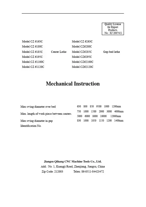
QualityLicensefor ExportProductsNo.: XJ 2007421Model CZ 6163C Model CZ 6263CModel CZ 6180C Model CZ6280CModel CZ 6185C Center Lathe Model CZ6285C Gap-bed latheModel CZ 6195C Model CZ6295CModel CZ 61100C Model CZ62100CModel CZ 61120C Model CZ62120CMechanical InstructionMax swing diameter over bed 630 800 850 9500 1000 1200mmMax. length of work piece between centers 750 1000 1500 2000 3000 4000mm 5000 6000 8000 10000 12000mmMax swing diameter in gapIdentification No.830 1000 1050 1150 1200 1400mmJiangsu Qihang CNC Machine Tools Co., Ltd.Add.: No. 1, Kuangji Road, Zhenjiang, Jiangsu, ChinaZip Code: 212003 Telex: 86-0511-********ContentI. Notice on use of the machine tool and safety measures thereof (2)II. Main purposes of the machine tool (8)III. Main technical parameters of the machine tool (8)IV. Transmission system of the machine tool and its structure (12)V. Lubrication and cooling of the machine tool (20)VI. Manipulation, adjustment and safety maintenance of the machine tool (21)VII. Conveying, installation and commissioning of the machine tool (37)VIII. Distribution diagram and list of rolling bearings of the machine tool (38)Ⅸ. Catalog and working diagram of wearing parts of the machine tool (48)X. Jointing techniques for bed, lead screw and feed rod (55)I. Notice on use of the machine tool and safety measures thereof1. Notice on operation1). The operator must accept skill trainings before operating on the machine.2). The operator shall refer to Instructions on Mechanical and Electrical Safety before using the machine tool for the first time, sufficiently lubricating each part as required and activating the machine tool only after having had a full understanding of positions and purposes of each handle and button.3). Before activating the machine during each shift, it is required to check the cleanness of various lubricating surfaces, sufficiency of lubricants as well as fastness of screw-nails on various places in addition to running each part idly for a short period.4). In case the machine tool is to be restarted after a long stop, it shall first idle for a certain period of time and shall be put into production only after all parts have been confirmed to be in a normal state.5). In case the spindle and gears in the feeding box are rotating, no change to rotational speed or feeds shall be made. Where any changes are required, it is imperative to stop the operation and place each gear-shift handle at specified positions in accordance with the label plate on the machine tool.6). When the tool post is moving at a fast pace, the direction of such a rapid move shall first be determined before pressing down the fast forward button.7). When utilizing the tailstock to support and hold the work-piece, the locking nuts between the bed and the tailstock as well as the locking handle of the tailstock sleeve shall be fastened.8). When adopting centers for processing, please pour oil onto centers and stop the machine immediately upon discovery of an over-heating center. It is not allowed to operate with damaged centers.9). Where steady rest and traveling rest are used for supporting the turning of work-piece, the contacting place between the support and the work-piece shall be lubricated.10). The voltage of the grid shall be kept in the range of AC380±15% so as to ensure normal operation.2. Maintenance and proper use1). It is not allowed to place any articles tend to damage the machine tool on the finishing surface or each guide-way surface of the machine tool.2). It is required to add oil, change oil and check the oil inlet/outlet within the spindlebox according to the lubrication diagram on a regular basis so as to prevent the oil inlet/outlet from clogging.3). The lubricant shall be replaced once within one month after the initial use of the machine tool and since then it shall be replaced every two months.4). When replacing the lubricant, strictly filter and clean the same so as to prevent bearings and gears from damaging.5). When the work is finished, clean the guide-way surface and apply an oil coating thereto.(6) The machine tool shall be kept working under good working conditions. Such situations as abnormal noises, smokes, heats or damages shall be reported to relevant personnel in time upon discovery and shall be inspected after the machine is off.(7) The tightness degree of the triangular belt shall be inspected on a regular basis so as to maintain a good working status.(8) The maintenance of the machine tool shall be carried out on the prerequisite that the machine is off.(9) Please refer to drawings of relevant parts before carrying out maintenance or repair.(10) The repairman eligible to repair this machine tool shall have a clear understanding of its structure and obtain mechanical and electrical knowledge to a certain degree.3. Safety knowledge(1) Concentrate on works and always maintain safety consciousness. It is forbidden to smoke while working or operate the machine tool when drunk.(2) When operating the machine tool, no such accessories as tie, watch, ring and diamond is allowed to wear. People will get hurt if come in contact with rotating parts, so do not get close to the rotating head of the spindle in operation or hold the rotating part.(3) Various kinds of spanners, tools and parts shall be kept away from the spindle, work station or moving parts of the machine tool.(4) The ground around the machine tool shall always keep clean. No iron scraps shall accumulate on the ground or machine oil and liquid coolant spill over onto the ground, thus influencing the machine tool.(5) When the machine tool is running, do not put hands at somewhere close to the tool or moving devices.(6) Before running the machine tool, it is required to grip the work-piece and the clamp; otherwise, the machine tool shall not be started up.(7) The machine tool has to stop running when changing the tool.(8) The guard door of the change-gear device is not allowed to be open during work, soas to prevent abrupt power failure which might bring avoidable accidents.(9) The operator shall keep in mind positions of all emergency stop buttons, so as to be ready for any eventualities.(10) The tailstock is equipped with an unloading devise, so please be careful when pulling it.(11) The power supply must be cut off when examining and repairing the machine tool.(12) People getting an electrical shock of high voltage may die. Thus, person in charge of the implementation of maintenance and repair of electric appliances shall limit to those who have acquired knowledge on circuits of the machine tool and have accepted trainings on safety issues of electric appliances. The work shall be carried out only when the main power source has been cut off and an indication of “in operation” has been marked.(13) The cutting fluid, machine oil and cutting powders spilled over on the ground might hurt people by letting them fall over themselves or hit somewhere. Cut off the power of the machine and clean the interior of the machine and surrounding areas before operating the same. During installation and operation, it is required to wear safety helmet and protective shoes.(14) If any tools or work-pieces get stuck by the machine tool which activates abruptly, the broken and damaged ones might fly off and seriously hurt people. It is strongly required to cut off the power before carrying out maintenance and inspection.(15) In case the spindle is rotating, no change to rotational speed or feeds shall be made. When using three-jaw chuck and four-jaw chuck, their specification shall not exceed Ф630mm. Where four-jaw chuck of Ф4000mm is used, the rotational speed of the spindle shall not go beyond 380rpm. The Specification mainly aims at equipping the operator with a preliminary knowledge of the machine tool’s performance, proper operation, simple adjustment and maintenance. For profounder understanding and special requirement, please contact the After-sale Service Department of our company.Fig.1: Profile drawing of the machine toolFig.1: Profile drawing of the machine tool (5M 6M)Fig.1: Profile drawing of the machine tool (8M 10M 12M)II. Main purposes of the machine toolThis machine tool is capable of various coarse and fine turning of ferrous metal, nonferrous metal and non-metal work-pieces, such as turning of inner and outer cylindrical surfaces, conical surface and other surfaces of revolution. It is also capable of turning of end faces and various metric, inch, module and pitch threads in common use as well as multiple-threads. Moreover, it enables drilling, reaming, oil channeling and so on thereon. The dimensional accuracy of work-pieces processed on this machine tool can reach IT7 level, with its roundness error being no larger than 0.01 and its cylindricity on 300 mm length being no larger than 0.03. Its surface roughness can reach 1.6 (for standard sample piece).III. Main technical parameters of the machine tool310mm CZ6163C CZ6263C 400mm CZ6180C CZ6280C 425mm CZ6185C CZ6285C 475mm CZ6195C CZ6295C 500mm CZ61100C CZ62100C Central Height600mm CZ61120CCZ62120C 630mm CZ6163C CZ6263C 800mm CZ6180C CZ6280C 850mm CZ6185C CZ6285C 950mm CZ6195C CZ6295C 1000mm CZ61100C CZ62100C Max. Swing Diameter over Bed1200mm CZ61120CCZ62120C 345mm CZ6163C CZ6263C 485mm CZ6180C CZ6280C 535mm CZ6185C CZ6285C 635mm CZ6195C CZ6295C 685mm CZ61100C CZ62100C Max. Swing Diameter over Tool Post800mm CZ61120CCZ62120C830mm CZ6263C Max. Swing Diameter over Gap (Saddle Machine tool)l000mmCZ6280C1050mm CZ6285C1150mm CZ6295C1200mm CZ62100C1400mm CZ62120CMax. Turning Length 450/700/1200/1600/2600/3600/4600/560/7600/9600/11600mmWidth of Bed Guide-way 550mmSpindle Taper 1:16Taper of Spindle Center Sleeve No.6 (Morse)Spindle Bore 105mmRotational Speed Step/RangeClockwise 18 Steps 14-750 r/minof Spindle Counterclockwise9 Steps 21-857 r/min Kinds and Ranges of FeedsBasic FeedsLongitudinal 32 Kinds 0.10-1.42 mm/rCross 32 Kinds 0.03-0.45 mm/r Fine FeedsLongitudinal 8 Kinds 0.048-0.089 mm/rCross 8 Kinds 0.015-0.028 mm/r Increased FeedsLongitudinal 32 Kinds 1.52-22.8 mm/rCross 32 Kinds 0.48-7.2 mm/r Kinds and Ranges of ScrewingMetric Thread 54 Kinds 1-240Inch Thread 37 Kinds l-28 threads/inchModule Thread 45 Kinds 0.5~60mmPitch Thread 27 Kinds l-30 threads/inchMax. Travel of Top Slide 230mmMax. Travel of Cross Slide 400mmDistance from Spindle32mmCenterline to Tool BearingSurfaceCross-Section of Tool 30×30mmDiameter of Tailstock Spindle Ф100mm or Ф120mm Taper of Tailstock Spindle No.5 or 6 (Morse)Max. Travel of Tailstock Spindle200mm Y160M-4Power 11KW Model of Main MotorRotational Speed1460 r/minYS5634 Power0.12 KW or 0.18 KW Model of Rapidly-Traveling Motor of ApronRotational Speed1400 r/minLongitudinal 6 m/minRapid Traveling Speed of Apron Cross 2 m/min AB-25 or AB-100Power 0.09 KW or 0.12 KW Model of Cooling MotorFlow25 L/min or 100 L/min1000 kg CZ6163C CZ6263C Max. Weight between Two Centers1200 kgCZ6180CCZ6280C and aboveLength of BedExternal Dimensions of Machine Tool(L×W×H)Weight of Machine Tool (approximately, t)750 2702×1276×1260 3.8 1000 2952×1276×1260 4.0 1500 3452×1276×1260 4.5 2000 3952×1276×1260 5.0 3000 4952×1276×1260 5.5 4000 5952×1276×1260 6.5 5000 6952×1276×1260 9 6000 7952×1276×1260 10 8000 9952×1276×1260 11.5 10000 11952×1276×1260 13 12000 13952×1276×126014.5F i g .2: D i a g r a m o f t h e m a c h i n e t o o l t r a n s m i s s i o n s y s t e mn =1460 r /m i nIV. Transmission system of the machine tool and its structure(I) Machine tool transmission systemShown in Fig.2 is the machine tool transmission system.1. Main transmission systemThe work-piece shall be clamped on the chuck or between two centers. The motor drives the spindle via transmission of belts and gears so as to rotate the work-piece.There are two routes for its rotational transmission in clockwise direction, having been divided into 18 steps.Low-speed portion: (14-190 r/min)Main motor →Shaft I →Shaft II →Shaft III →Shaft IV →Shaft V →Shaft VI (Spindle) High-speed portion: (230-750 r/min)Main motor →Shaft I →Shaft II →Shaft III →Shaft V →Shaft VI (Spindle)There are also two routes for its rotational transmission in counterclockwise direction, having been divided into 9 steps.Main motor →Shaft I →Shaft VII →Shaft II →Shaft III→Shaft IV →Shaft V →Shaft VI Shaft V→ Shaft VI2. Feeding transmission systemThe feeding motion of the machine tool is enabled by the feeding box and apron. Its transmission route is: Headstock’s Shaft III or Shaft V →Shaft VIII →Shaft IX (or Shaft VIII →Shaft X →Shaft IX) →Change-Gear Bracket →Feeding box →Apron. The longitudinal, cross, clockwise and counterclockwise feeding motion of the machine tool can be realized via change of directions within the apron.3. Rapid movement of the tool carriage of the machine toolThe rapid movement of the tool carriage of the machine tool is realized by the rapidly-traveling motor installed on the apron.(II) Explanation on the structure of main subassemblies1. BedThe guide-ways of the bed include two planar ones and two rhombic ones. The front rhombic guide-way and the rear planar guide-way are used by the tool carriage, while the rest are for the tailstock and steady rest.2. Spindle boxThe rotational motion of the spindle is enabled by the main motor via the action of triangular belt and gear shift, having been divided into 18 steps. Its rotational speed ranges from 14 r/min to 750 r/min.A fiction clutch is installed on Shaft I of the spindle box so as to protect the transmission component of the machine tool as well as realize clockwise and counterclockwise rotation of the spindle in a convenient way without stopping the rotation of the main motor.The Shaft III and Shaft V of the spindle box lie in the same centerline and they can be joined together directly via internal gear 18 and gear 19 under the condition that gears 14, 15, 16 and 17 are disengaged in respect to each other (see Fig.2), thus realizing branch transmission of spindle rotation.The front bearings of the spindle are adjustable double-row short centripetal cylindrical roller bearings while the rear ones are single-row tapered roller bearings. In addition, single-direction thrust ball bearings are installed on the rear end of the spindle so as to bear axial load.The spindle box is an enclosed box which adopts splash lubrication.The maximum tolerable torque at gears of the spindle box is 1500N m.3. Feeding boxThe feeding box is a two-shaft sliding gear mechanism made up of three parts, namely, basic group, multiplication group and inch/mm conversion group.The feeding box is an enclosed box which adopts centralized lubrication by manual oil-pump.Operating relevant handles while shifting change-gears as per the upper pitch of the feeding box and the indication on the label plate of feeds may acquire different pitches of various screw threads and feeds.4. Apron (See Fig.3)It is mainly used to transfer the motion of the feed rod or lead screw to the tool post so as to provide the tool post with power-driven feeds in cross/longitudinal direction or screwing.In order to avoid interferences of power-driven feeds with the motion of screwing mechanism, an interlocking mechanism is installed in the apron for preventing these two motions from happening simultaneously. Also provided in the apron is an out-of-gear worm security device to avoid extremely heavy loads of the feed mechanism. In order to reduce the labor intensity of the operator, the apron is equipped with a rapidly-traveling motor and amechanical/electrical interlocking stopper to ensure that the motor won’t be activated during the process of power-driven feeds.5. Tool post (See Fig.4)The tool post can not only be driven in longitudinal direction along the bed and in cross direction along the cross slide but also be operated manually or traveling rapidly. But the compound rest can only be operated manually.The tool post swivel (1) can rotate 60° in left and right directions respectively in relation to the tool carriage (2) so as to facilitate the turning of conical parts.For machine tools of models above CZ6180C, the quadrate base of the cross slide can be properly adjusted in cross direction along the slide so as to broaden the processing scope of various parts.6. Tailstock (See Fig.5)The tailstock is tightly fixed onto the bed by the clamping plate (1) and this can be realized by rotating the locking handle (6) or nuts (7). For turning of long but less tapered work-pieces, the upper body of the tailstock (4) shall move crossly on the tailstock base (5) by bolts (2) and nuts (3) for the sake of center shift.The movement of the tailstock sleeve (8) is realized by the hand-wheel (9) while its locking and loosening are realized by the handle (10).The tailstock base (5) is equipped with an unloading device for facilitating the movement of the tailstock. It is made up of a disc spring (11), a rolling bearing (12) and subassemblies (13), (14) and (15). The screw-nail (16) is used as an axial limit.7. Steady rest (See Fig.6)The steady rest is used as a support when processing slender shaft components so as to prevent any bending caused by cutting force. The clamping scope is Ф20-145mm for CZ6163C or Ф20-185mm or Ф300mm for series above CZ6180C. It can also be used for processing parts with large length under circumstances where using the tailstock as the support is inappropriate.The traveling rest is a steady rest moving alongside with the tool post while fixed on the carriage. The clamping scope is Ф20-105mm for CZ6163C or Ф20-135mm or Ф180mm for series above CZ6180C.Fig.3: ApronV. Lubrication and cooling of the machine tool1. The spindle box of the machine tool adopts splash lubrication while the feeding box and apron adopt centralized lubrication by manual oil-pump. The rest utilize manual lubrication by oiling. For specific parts to be lubricated and the requirement thereof, please refer to the indications about machine tool lubrication on the label plate. Since part of the lubricant cannot return to the apron after having reached guide-ways of the bed, the apron shall be refilled with some lubricant according to specific situations so as to ensure that the surface of the lubricant is maintained at a certain level within the apron. The lubricant shall be filled to a depth of 80 mm in the spindle box where the oil scale for CZ6163C is placed. The lubricant shall be filled to a position reaching half of the orifice for series above CZ6180C. The feedbox needs 1.0L oil. The above-mentioned machines and components normally require HJ30 oil.2. The liquid coolant for the machine tool shall be replaced every three months in case of processing of casting and every six months in case of processing of steel parts. The coolant shall be replaced immediately upon deterioration and the water tank shall also be cleaned in time therewith, where the scrap iron shall be cleared by the magnet.3. The cooling system of the machine tool (See Fig.7).VI. Manipulation, adjustment and safety maintenance of themachine tool(I). Manipulation of the machine tool1. For information on positions of various manipulation handles of this machine tool, please refer to Fig.8, while for information on their names, please refer to Sheet2.2. Manipulating method of the main transmission systemThe rotational speed of the spindle is achieved by switching handles (1), (2) and (5), where the handle (5) has three positions marked as 1:1, 1:4 and 1:16, respectively. The handle (5) enables low-speed transmission at the position of 1:4 or 1:16 and can obtain a rotational speed of step 12 in clockwise direction and another of step 6 in counterclockwise direction when in cooperation with handles (1) and (2). In case a high-speed transmission is required, please turn the handle (5) to the position of 1:1 where a rotational speed of step 6 in clockwise direction and another of step 3 in counterclockwise direction can be attained in cooperation with handles (1) and (2).The manipulation handle (21) or (28) has three positions, where the spindle rotates in clockwise direction when the handle is lifted up and rotates in counterclockwise direction when the handle is pressed down. The spindle stops rotation when the handle is place at the middle position.The machine tool must be stopped when the gear shift handle is in operation; otherwise transmission gears might be damaged.3. Operating method of the feeding systemThe feeding motion is realized through proper switch of handles (3) and (4) of the headstock and handles (15), (16), (17) and (20) on the feeding box. The handles shall be placed at proper positions as indicated on the label plate above them.(1) The handle (3) is a handle for left/right threads. Aligning it with the mark□ can produce right-hand threads and feeds in clockwise direction; while aligning it with the mark□can produce left-hand threads and feeds in counterclockwise direction. No feeding motion will be generated when it is placed at the middle position.(2) The handle (4) is a standard handle for pitch enlargement. Aligning it with the mark□1/1 can attain basic pitch and basic feeds; while aligning it with the mark□ x/1 can attain enlarged pitch and increased feeds. No feeding motion will be generated when it is placed at the middle position.F i g .8: P o s i t i o n D i s t r i b u t i o n D i a g r a m o f M a n i p u l a t i o n H a n d l e s o f t h e M a c h i n e T o o lF i g .8: P o s i t i o n D i s t r i b u t i o n D i a g r a m o f M a n i p u l a t i o n H a n d l e s o f t h e M a c h i n e T o o l (5M 6M )F i g .8: P o s i t i o n D i s t r i b u t i o n D i a g r a m o f M a n i p u l a t i o n H a n d l e s o f t h e M a c h i n e T o o l (8M 10M 12M )Name Sheet of Various Manipulation Handles of the Machine Tool Sheet 2Numerals in DistributionDiagram of VariousManipulation Handles ofthe Machine ToolNames1 Gear Shift Handle for Changing the Rotational Speed of the Spindle of the Machine Tool2 Gear Shift Handle for Changing the Rotational Speed of the Spindle of the Machine Tool3 Handle for Left/Right Threads4 Standard Handle for Pitch Enlargement5 1:1, 1:4, 1:16 Gear Shift Handle for Changing the Rotational Speed of the Spindle6 Button for Starting/Stopping the Machine Tool7 Handle for Moving the Cross Slide8 Handle for Moving the Top Slide9 Handle for Clamping/Loosening the Quadrate Tool Post10 On/Off Button for the Coolant11 Button for Rapidly Moving the Slide12 Handle for Locking/Loosening the Spindle of the Tailstock13 Hand-wheel for Moving the Spindle of the Tailstock14 Handle for Locking/Loosening the Tailstock15 Handle for Inch/mm Conversion of Threads16 Hand-wheel for Speed Adjustment of the Basic Group17 Hand-wheel for Speed Adjustment of the Multiplication Group19 Handle for Lubricating the Feeding Box by Manual Oil-Pump20 Handle for Connecting the Lead Screw and the Feed Rod21 Handle for Manipulating the Spindle Rotation in Clockwise/Counterclockwise Direction22 Hand-wheel for Moving the Slide in Longitudinal Direction23 Hand-wheel for Switching Feeds in Clockwise/Counterclockwise Direction24 Handle for Lubricating the Apron by Manual Oil-Pump25 Handle for Feeds in Longitudinal/Cross Direction26 Handle for Manipulating Slit Nuts27 Handle for Manipulating the Out-of-Gear Worm28 Handle for Manipulating the Spindle Rotation in Clockwise/Counterclockwise Direction(3) The handle (15) on the feeding box is a handle for inch/mm conversion of threads.Placing the handle (15) at means cutting of metric and module threads in addition togaining feeds; while at means cutting of inch and pitch threads.The handle (16) is a manipulation hand-wheel for the basic group, and there are 1-8 positions indicated on its label. By aligning it with points indicated on the guard ring respectively, the pitches and feeds can be switched in sequence. In order to change the position of the hand-wheel (16), it is required to pull out the same and rotate it to the desired position before pushing it in. The hand-wheel can rotate in both clockwise and counterclockwise directions during manipulation.The handle (17) is a shift handle for the multiplication group, bearing I-IV positions. By aligning the Roman numerals with the L above them respectively, multiplied pitches and feeds can be attained. The handle (17) can rotate in both clockwise and counterclockwise directions during manipulation.The handle (20) is a handle for switching between the lead screw and the feed rod.Placing the handle (20) at will enable feed-rod transmission so as to realizepower-driven feeds of the tool post; while placing it at will enable lead screw transmission, thus processing various threads.The above-mentioned handles shall work in proper cooperation with other and with gears in Fig.9 as per locations indicated on the label plate of pitches and feeds so as to attain the desired feeding motion.(4) When processing threads with a dimension of 19 threads /inch, change the ratio of gears as required in Fig.12 and, at the same time, place the hand-wheel (16) at the position of numeral “7” and the hand-wheel (17) at “I”.4. Control of tool post motions(1) When cutting the threads, the movement of the tool post shall be controlled by thehandle for slit nuts (26). Press down the handle (26) to the position of , then the apron will be driven directly by the lead screw. The carriage will stop moving when the handle is lifted up.(2) Power-driven feeds of the tool post in longitudinal/cross direction shall be driven by the feed rod and controlled by handles (23), (25) and (27). The handle (23) is a handle for switching feeds in clockwise/counterclockwise direction. Feeds in clockwise direction can be achieved by aligning the mark indicated on the label of the handle (23) with the right T; while those in counterclockwise direction can be achieved by aligning the markwith the right T.The handle (25) is a handle for switching feeds in longitudinal/cross direction. Feeds orrapid movement in longitudinal direction can be achieved by aligning the mark indicated on its label with the upper T; while those in cross direction can be achieved byaligning the mark with the upper T.The handle (27) is a handle for controlling the out-of-gear worm. When lifting up the handle, the worm engages with the worm wheel, thus realizing power-driven feeds in the direction matching with the handle (25). When pressing down the handle, the worm disengages with the worm wheel so as to stop power-driven feeds. During the process of power-driven feeds, the handle (27) will fall off automatically when the resistance against feeds of the tool post in longitudinal direction reaches 5830N, thus serving as a security mechanism.(3) The manual control of the tool post can be realized via hand-wheel (22) and (7). Both hand-wheels are equippted with reading devices where an illuminating device is provided above the reading device of the hand-wheel (22). The hand-wheel (22) can control the manual longitudinal motion of the tool post in clockwise/counterclockwise direction; while the hand-wheel (7) can control the manual cross motion of the tool post in forward/backward direction.(4) In order to reduce the labor intensity of the operator, this machine tool is equipped with a rapidly-traveling device, which can be realized via cooperation by the button box (11)and the handle (25). When the handle (25) is placed at the position of , activating the button to connect with the left button will enable the carriage to move rapidly towards left; while activating the button to connect with the right button will enable the carriage to moverapidly towards right. When the handle (25) is placed at the position of , activating the button to connect with the left button will enable the tool post to move rapidly in forward direction; while activating the button to connect with the right button will enable the tool post to move rapidly in backward direction. The rapid motor can only be activated when the button is pressed down, and it will stop rapid movement as soon as the button is loosened. When the rapid motor is activated, the handle (27) must be put down. If the handle (27) is at “connected” position (namely, if the power-driven feeds are activated), then activating the button will not generate rapid movement (An interlocking device for power-driven feeds and rapid movement is provided in the apron).(5) In order to prevent lead screw and feed rod from interfering with each other and thus causing damages to various parts, an interlocking mechanism is provided in the apron. When the handle (25) stays at the middle position, the handle for slit nuts (26) can be connected in downward direction and if the handle (25) stays elsewhere, the handle for slit nuts (26) is unable to be connected. Also, when the handle for slit nuts (26) is connected in downward direction, then the handle (25) is unable to turn to other positions.(6) In order to prevent feeds and rapid motions from interfering with each other and thus causing damages to various parts, another interlocking security mechanism is also provided in。