
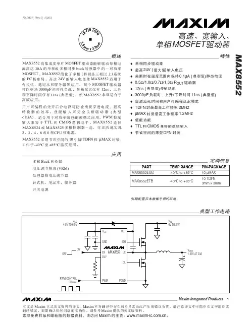
MAX8552_cn
- 格式:pdf
- 大小:508.09 KB
- 文档页数:11

Eaton Electric Limited,Great Marlings, Butterfield, Luton Beds, LU2 8DL, UK.Tel: + 44 (0)1582 723633 Fax: + 44 (0)1582 422283E-mail:********************The MTL4851 and MTL4852 HART connection system provides a simple interface between smart devices in the field, control systems and HART instrument management software run on a pc.The system is based on 16-channel modularity to provide a compact, easily configurable and expandable system. Using a standard RS485 serial link up to 7936 HART devices can be connected on a single network.For the optimum solution, choose from a range of general purpose and IS termination boards. F or maximum flexibility the HMM64 HART backplane locates an MTL4851 master communications module and up to three MTL4852 secondary interface modules, with each module connecting to 16 field devices. General purpose HART connection units and IS backplanes are available fitted with an cable interface connection to the HMM64. This system can be extended with further HMS64 HART backplanes linked to the master, each carrying up to four MTL4852 secondary interface modules.The M TL4851 and M TL4852 modules can also be located on HTP-SC16x termination boards for general purpose applications. HART loops are simply wired through these HART Termination Panels and may be grounded or floating circuits. The HTP boards offer a compact and cost-effective solution for general applications. CPH-SC16x backplanes are ideal for signal loops requiring intrinsic safety (IS) protection, combining multiplexer and IS isolator mounting. This offers considerable simplification in wiring when compared to DIN-rail based solutions.The HCU16 HART units connect to 16 general purpose field instrumentswhile maintaining channel to channel isolation. Resistor conditioning options are compatible with all types of I/O cards. It allows pass-throughconnections for transmitter power supply, input signal and common.The HCU16AO unit includes HART filters for use with I/O cards that areincompatible with HART communication signals.Customised backplanes and connection units are available to provide direct connection from DCS I/O cables, replacing the standard termination boards.MTL4851 and MTL4852HART® connection systemsSee also the MTL4850 datasheet for alternative HART solutions using a 32 channel multiplexer module ideally suited for use in conjunction with emergency shutdown and safety systems.Connectivity to HART Configuration and Instrument Management Software :The online access to the information contained within HART devices allows users to diagnose field device troubles before they lead to costly problems. Software can capture and use diagnostic data from HART field instruments via the MTL HART connection hardware. This allows users to realise the full potential of their field devices to optimise plant assets, which results in significant operations improvement and direct maintenance savings.IMS products provide essential configuration, calibration, monitoring and maintenance history functions for conventional analogue (4-20 mA) and HART protocol compatible smart process instruments and fielddevices. They deliver powerful tools to meet the need for standardised instrument maintenance procedures and record keeping mandated by some quality standards and regulatory bodies.The benefits of utilising these powerful software packages online include:• Reduced commissioning time and costs • Reduced maintenance costs• Reduced documentation • Reduced process downtimeThe MTL485x offers connectivity to a comprehensive range of F DTbased software packages via the comms Device Type Manager (DTM).The DTM can be downloaded from . Other softwarepackages, such as AMS from Emerson, work with the MTL485x through custom software drivers or by the inclusion of the device description (DD)file for the MTL multiplexers.• Designed to mount directly to a range of general purpose HART ® connection units and IS backplanes• Provides a simple interface to smart devices in the field• Connect up to 7936 HART ® devices on a single RS485 network• LED indication for fault diagnosis • Auto baud rate detection• Connectivity to HART ® configuration and Instrument Management software (IM S)HART ® is a registered trademark of the HART Communication FoundationSYSTEM OVERVIEW (TYPICAL INSTALLATION)LED INDICATORS - MTL4851 moduleLED INDICATORS- MTL4852 moduleSPECIFICATIONMTL4851 Master Communications Module Number of HART channels16 (ch1 to ch16)Channel device typeHART rev 5-7Channel interface2 connections to each channelHost system interfaceRS485 2-wire multidrop(up to 31 MTL4851 modules can be connected to one host)RS485 baud rate38400, 19200, 9600, 1200 baud - auto detected Address selectionup to 31 addresses, set on backplaneAlarm outputOpen-collector transistor, referenced to 0VVmax = 35V, Imax= 5mA, Pmax= 100mWMTL4852 Secondary Interface ModuleNumber of HART channels16 (ch17 to ch256 in 16 channel groups)Channel device typeHART rev 5-7Channel interface2 connections to each channelMTL systems interfaceUp to 15 off MTL4852 modules per MTL4851Total length of interface bus, 4m max.Power requirementsPowered from MTL4851 moduleISOLATIONChannel-to-channel isolation50V dcField loop isolation50V dcModule is coupled to loops via capacitor in eachconnection leg (i.e. 2 capacitors per channel)RS485 interface isolation (Between module and interface) 50V dcAlarm output isolation (Between module and output) 50V dcPSU isolation (Between module and PSU input) 50V dcPOWER SUPPLY, MTL4851 (from backplane)Supply voltage19V to 35V dcCurrent consumption42mA at 24V ±10% for MTL4851, plus2mA for each MTL4852Power dissipation (MTL4851 + 15 MTL4852)<1.6W at 24V ±10% ENVIRONMENTALTemperature rangeOperating: –40°C to +60°CNon-operating: –40°C to +85°CRelative humidity5% to 95% - non-condensingMECHANICALDimensionsSee drawingWeightMTL4851 95gmMTL4852 75gmApprovalsFor the latest certificate information,see /certificatesDIMENSIONS (mm)INSTRUMENT MANAGEMENT SOFTWAREThe MTL HART Connection System offers connectivity to a comprehensive range of both general instrument management software packages and dedicated software packages for optimising Valve positioner performance and maintenance including-For software packages that are based on a FDT frame i.e FieldCare,PACT ware etc communication with the MTL HART multiplexersystem requires the MTL Generic Communications DTM. This can bedownloaded Free of Charge from the MTL website.HMM64/HMS64 BACKPLANECapacityHMM64 1xMTL4851, 3xMTL4852HMS64 4xMTL4852Max. 3xHMS64 connected to 1xHMM64 Maximum power requirements1.9W for fully equipped HMM64, plus3 HMS64 backplanes.HART interface connectors4xDIN41651 20-way HART signal cables(16 HART signal connections + 4 common returns)For use with HM64RIB20 cablesBackplane inter-connectHMM64 1x DIN41651 16-way socketHMS64 2x DIN41651 16-way socketFor use with HMRIB16 cablesotherHMx64HMM64HMS64Weight (excl. modules)215g approx.Power requirements, Vs21 to 35V dc through plug-in connectors, screw-secured4 terminals for dual power suppliesRS485 port2 terminals for bus, plus screen terminal6 terminals in total to enable chained bus connection.HART address switch, five poles active in six position switchAlarm connectors2 terminals for alarm output and alarm clearConductor terminalsAccept conductors of up to 2.5mm2 stranded or single-core BACKPLANES FOR MTL4851/MTL4852GENERAL PURPOSE VERSIONSHTP-SC16M/HTP-SC16S BACKPLANE *Capacity HTP-SC16M 1xMTL4851 HTP-SC16S 1xMTL4852Max. 4xHTP-SC16S connected to 1xHTP-SC16MMaximum power requirements 1.3W for HTP-SC16M, plus4 HTP-SC16S backplanes.Signal connectors2.5mm 2 screw-clamp terminals2 terminals per channel for field and system Backplane inter-connect HTP-SC16M 1x DIN41651 16-way socket HTP-SC16S 2x DIN41651 16-way socketFor use with HMRIB16 cablesWeight (excl. modules) 300g approx.Power requirements, Vs21 to 35V dc through plug-in connectors, screw-secured 4 terminals for dual power suppliesRS485 port2 terminals for bus, plus screen terminal6 terminals in total to enable chained bus connection.HART address switch, five poles active in six position switch Alarm connectors2 terminals for alarm output and alarm clearConductor terminalsAccept conductors of up to 2.5mm 2 stranded or single-core * for further details of the model options refer to the Instruction Manual INM4851 - available from the MTL website.Connection from anHTP-SC16M HTP-SC16SBACKPLANES FOR MTL4851/MTL4852 GENERAL PURPOSE VERSIONSHCU16 HART CONNECTION UNIT*Accuracy (HCU16-P250 only)250Ω ±0.05%Connectors2.5mm 2 screw-clamp terminals 3 terminals per channel20-way HART signal cable (to HMM64/HMS64)Weight383g approx.HCU16AO CONNECTION UNIT WITH FILTERSSeries impedancedc < 2ΩHART signal > 240ΩConnectors2.5mm 2 removable, screw-clamp terminals 2 terminals per channel in groups of 4 channels 20-way HART signal cable (to HMM64/HMS64)Weight768g approx.COMMON SPECIFICATION HCU16 & HCU16AOCapacity16 channelsIsolationChannel-to-channel 50V dcMountingSupplied fitted in DIN-rail (T- or G- section) carrier* for further details of the model options refer to the Instruction ManualBACKPLANES FOR MTL4851/MTL4852 GENERAL PURPOSE VERSIONSHCU16Contact Eaton’s MTL product line with details of your specific requirements.CPH-SC16M/CPH-SC16S BACKPLANES CapacityCPH-SC16M 1xMTL4851CPH-SC16S 1xMTL485216 x MTL4541/A/S/AS, MTL4546/Y isolators Max. 4xCPH-SC16S connected to 1xCPH-SC16MPower requirements, Vs21 to 35V dc through plug-in connectors,2 x 4 terminals for dual power supplies and power chain Dual 2.5A medium blow TE5 fuses Maximum power requirementsCPH-SC16M 0.65A CPH-SC16S 0.6ASafe-area signal connectors2.5mm 2 screw-clamp terminals2 terminals per channel for system connections Backplane inter-connectCPH-SC16M 1x DIN41651 16-way socket CPH-SC16S 2x DIN41651 16-way socketFor use with HMRIB16 cablesRS485 port 2 terminals for bus, plus screen terminal6 terminals in total to enable chained bus connection.HART address switch, five poles active in six position switch Alarm connectors 2 terminals for alarm output and alarm clear AccuracyCPH-SC16xR: 250 Ω ±0.05% conditioning resistors(note: MTL4541/41A only)Weight (excl. modules and accessories)410g approx.* for further details of the model options refer to the Instruction Manual INM4851 - available from the MTL website.BACKPLANES FOR MTL4851/MTL4852 INTRINSIC SAFETY VERSIONSRedundant RS485Alarm connecting to hazardous area HART multiplexer HART to anRedundant to and from CPH-SC16x backplanesconnecting to hazardous area HART multiplexerCPH-SC16MCPH-SC16SThe given data is only intended as a productdescription and should not be regarded as a legal warranty of properties or guarantee. In the interest of further technical developments, we reserve the right to make design changes.Eaton Electric Limited,Great Marlings, Butterfield, Luton Beds, LU2 8DL, UK.Tel: + 44 (0)1582 723633 Fax: + 44 (0)1582 422283E-mail:********************EUROPE (EMEA): +44 (0)1582 723633 ********************THE AMERICAS: +1 800 835 7075*********************。

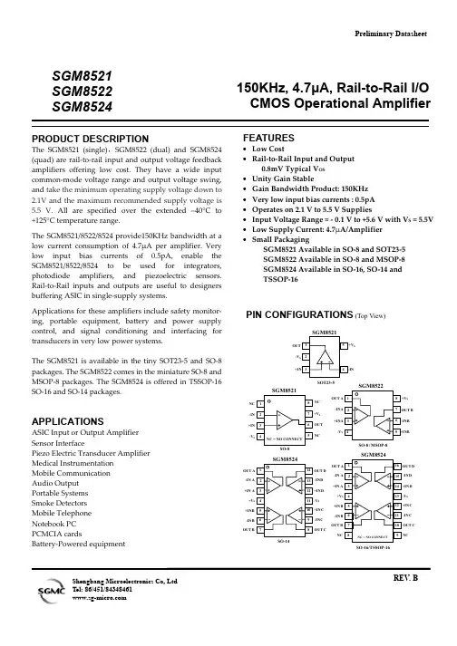
SGM8521 SGM8522 SGM8524PRODUCT DESCRIPTIONThe SGM8521 (single),SGM8522 (dual) and SGM8524 (quad) are rail-to-rail input and output voltage feedback amplifiers offering low cost. They have a wide input common-mode voltage range and output voltage swing, and take the minimum operating supply voltage down to 2.1V and the maximum recommended supply voltage is 5.5 V. All are specified over the extended –40°C to +125°C temperature range.The SGM8521/8522/8524 provide150KHz bandwidth at a low current consumption of 4.7µA per amplifier. Very low input bias currents of 0.5pA, enable the SGM8521/8522/8524 to be used for integrators, photodiode amplifiers, and piezoelectric sensors. Rail-to-Rail inputs and outputs are useful to designers buffering ASIC in single-supply systems.Applications for these amplifiers include safety monitor- ing, portable equipment, battery and power supply control, and signal conditioning and interfacing for transducers in very low power systems.The SGM8521 is available in the tiny SOT23-5 and SO-8 packages. The SGM8522 comes in the miniature SO-8 and MSOP-8 packages. The SGM8524 is offered in TSSOP-16 SO-16 and SO-14 packages.APPLICATIONSASIC Input or Output Amplifier Sensor InterfacePiezo Electric Transducer Amplifier Medical Instrumentation Mobile Communication Audio Output Portable Systems Smoke Detectors Mobile Telephone Notebook PC PCMCIA cardsBattery-Powered equipment150KHz, 4.7µA, Rail-to-Rail I/O CMOS Operational AmplifierFEATURES• Low Cost• Rail-to-Rail Input and Output0.8mV Typical V OS • Unity Gain Stable• Gain Bandwidth Product: 150KHz • Very low input bias currents : 0.5pA • Operates on 2.1 V to 5.5 V Supplies• Input Voltage Range = - 0.1 V to +5.6 V with V S = 5.5V • Low Supply Current: 4.7µA/Amplifier • Small PackagingSGM8521 Available in SO-8 and SOT23-5 SGM8522 Available in SO-8 and MSOP-8 SGM8524 Available in SO-16, SO-14 and TSSOP-16PIN CONFIGURATIONS (Top View)S NC-IN +IN -V SNC NC OUT +V S-V SOT23-5OUT B S -V SO-8 / MSOP-8OUT S +V -IND+IND SO-16/TSSOP-16-INB +INB -INC NCNCOUT BOUT C +INC OUT D OUT -V S +V -IND+IND-INC OUT BOUT C+INC OUT DShengbang Microelectronics Co, LtdPreliminary DatasheetREV . BELECTRICAL CHARACTERISTICS : V S = +5V (At R L = 500kΩ connected to Vs/2 and V OUT = Vs/2, unless otherwise noted)Specifications subject to change without notice.PACKAGE/ORDERING INFORMATIONMODEL ORDER NUMBER PACKAGEDESCRIPTIONPACKAGE OPTION MARKING INFORMATIONSGM8521XN5/TRSOT23-5Tape and Reel, 30008521 SGM8521SGM8521XS/TR SO-8 Tape and Reel, 2500 SGM8521XS SGM8522XS/TR SO-8 Tape and Reel, 2500 SGM8522XS SGM8522SGM8522XMS/TRMSOP-8Tape and Reel, 3000SGM8522XMS SGM8524XS/TR SO-16 Tape and Reel, 2500SGM8524XSSGM8524XS14 SO-14Tube SGM8524XS14SGM8524SGM8524XTS/TR TSSOP-16 Tape and Reel, 3000SGM8524XTSABSOLUTE MAXIMUM RATINGSSupply Voltage, V+ to V- . . . . . . . . . . . . . . . . . . . . . 7.5 VCommon-Mode Input Voltage. . . . . . . . . . . . . . . . . . . . (–V S ) – 0.5 V to (+V S )+0.5V Storage Temperature Range . . . . . . . . .–65℃ to +150℃ Junction Temperature . . . . . . . . . . . . . . . .. . . . . . . .160℃ Operating Temperature Range . . . . . . –55℃ to +150℃Package Thermal Resistance @ T A = 25℃SOT23-5, θJA .............................................................. 190/℃W SO-8, θJA ......................................................................125/W ℃ MSOP-8, θJA .............................................................. 216/W ℃ SO-16, θJA ..................................................................... 82/W ℃ TSSOP-16, θJA ............................................................ 105/W ℃ Lead Temperature Range (Soldering 10 sec).....................................................260℃ESD SusceptibilityHBM................................................................................4000V MM (400V)NOTES1. Stresses above those listed under Absolute Maximum Ratings may cause permanent damage to the device. This is a stress rating only; functional operation of the device at these or any other conditions above those indicated in the operational section of this specification is not implied. Exposure to absolute maximum rating conditions for extended periods may affect device reliability.CAUTIONThis integrated circuit can be damaged by ESD. Shengbang Micro-electronics recommends that all integrated circuits be handled with appropriate precautions. Failure to observe proper handling and installation procedures can cause damage.ESD damage can range from subtle performance degradation to complete device failure. Precision integrated circuits may be more susceptible to damage because very small parametric changes could cause the device not to meet its published specifications.TYPICAL PERFORMANCE CHARACTERISTICSAt T A = +25℃, V S = +5V , and R L =500k Ω connected to Vs/2,unless otherwise noted.Small-Signal Step Response Small-Signal Step Response50µs/div 50µs/divG = +1R L= 500K ΩC L = 20pFG = +1 R L= 500K ΩC L = 100pFG = +1 C L = 100pF R L= 500K Ω50m V /d i v50m V /d i v1V /d i vLarge-Signal Step Response100µs/divTYPICAL PERFORMANCE CHARACTERISTICS At T A= +25℃, V S = +5V, and R L=500kΩ connected to Vs/2,unless otherwise noted.APPLICATION NOTESDriving Capacitive LoadsThe SGM852X can directly drive 250pF in unity-gain without oscillation. The unity-gain follower (buffer) is the most sensitive configuration to capacitive loading. Direct capacitive loading reduces the phase margin of amplifiers and this results in ringing or even oscillation. Applications that require greater capacitive drive capability should use an isolation resistor between the output and the capacitive load like the circuit in Figure 1. The isolation resistor R ISO and the load capacitor C L form a zero to increase stability. The bigger the R ISO resistor value, the more stable V OUT will be. Note that this method results in a loss of gain accuracy because R ISO forms a voltage divider with the R LOAD.V IN V OUTFigure 1. Indirectly Driving Heavy Capacitive LoadAn improvement circuit is shown in Figure 2, It provides DC accuracy as well as AC stability. R F provides the DC accuracy by connecting the inverting signal with the output, C F and R Iso serve to counteract the loss of phase margin by feeding the high frequency component of the output signal back to the amplifier’s inverting input, thereby preserving phase margin in the overall feedback loop.V IN V OUTFigure 2. Indirectly Driving Heavy Capacitive Load with DC AccuracyFor no-buffer configuration, there are two others ways to increase the phase margin: (a) by increasing the amplifier’s gain or (b) by placing a capacitor in parallel with the feedback resistor to counteract the parasitic capacitance associated with inverting node. Power-Supply Bypassing and Layout The SGM852X family operates from either a single +2.5V to +5.5V supply or dual ±1.25V to ±2.75V supplies. For single-supply operation, bypass the power supply V DD with a 0.1µF ceramic capacitor which should be placed close to the V DD pin. For dual-supply operation, both the V DD and the V SS supplies should be bypassed to ground with separate 0.1µF ceramic capacitors. 2.2µF tantalum capacitor can be added for better performance.VnVpV SSV SS(GND)Figure 3. Amplifier with Bypass CapacitorsTypical Application Circuits Differential AmplifierThe circuit shown in Figure 4 performs the difference function. If the resistors ratios are equal ( R4 / R3 = R2 / R1 ), thenV OUT = ( Vp – Vn ) × R2 / R1 + Vref.Vn VpOUT Figure 4. Differential AmplifierInstrumentation AmplifierThe circuit in Figure 5 performs the same function as that in Figure 4 but with the high input impedance.Vn VpV OUT Figure 5. Instrumentation AmplifierLow Pass Active FilterThe low pass filter shown in Figure 6 has a DC gain of ( - R2 / R1 ) and the –3dB corner frequency is 1/2πR2C. Make sure the filter is within the bandwidth of the amplifier. The Large values of feedback resistors can couple with parasitic capacitance and cause undesired effects such as ringing or oscillation in high-speed amplifiers. Keep resistors value as low as possible and consistent with output loading consideration.V INV OUT Figure 6. Low Pass Active FilterPACKAGE OUTLINE DIMENSIONS SOT23-5PACKAGE OUTLINE DIMENSIONS SO-8PACKAGE OUTLINE DIMENSIONS MSOP-8PACKAGE OUTLINE DIMENSIONS SO-16PACKAGE OUTLINE DIMENSIONS TSSOP-16PACKAGE OUTLINE DIMENSIONS SO-14REVISION HISTORYLocation Page 11/06— Data Sheet changed from Preliminary to REV. AChanges to ABSOLUTE MAXIMUM ATINGS . . . . . . . . . . . . . . . . . . . . . . . . . . . . . . . .. . . . . . . . . . . . . . . . . . . . . . . . . . .. . . . . . . 3 11/06— Data Sheet changed from REV. A to REV. BAdds SO-14 Package . . . . . . . . . . . . . . . . . . . . . . . . . . . . . . . .. . . . . . . . . . . . . . . . . . . . . . . . . . . .. . . . . . . . . . . . . . . .. . . . . . 1, 3Shengbang Microelectronics Co, LtdUnit 3, ChuangYe PlazaNo.5, TaiHu Northern Street, YingBin Road Centralized Industrial ParkHarbin Development ZoneHarbin, HeiLongJiang 150078P.R. ChinaTel.: 86-451-84348461Fax: 86-451-84308461。

PACKAGING INFORMATIONOrderable Device Status(1)PackageType PackageDrawingPins PackageQtyEco Plan(2)Lead/Ball Finish MSL Peak Temp(3)5962-9563301Q2A ACTIVE LCCC FK201TBD POST-PLATE N/A for Pkg Type 5962-9563301QPA ACTIVE CDIP JG81TBD A42SNPB N/A for Pkg Type 77049012A ACTIVE LCCC FK201TBD POST-PLATE N/A for Pkg Type 7704901PA ACTIVE CDIP JG81TBD A42SNPB N/A for Pkg Type 77049022A ACTIVE LCCC FK201TBD POST-PLATE N/A for Pkg Type 7704902PA ACTIVE CDIP JG81TBD A42SNPB N/A for Pkg Type JM38510/12902BPA ACTIVE CDIP JG81TBD A42SNPB N/A for Pkg Type JM38510/12903BPA ACTIVE CDIP JG81TBD A42SNPB N/A for Pkg Type JM38510/12905BPA ACTIVE CDIP JG81TBD A42SNPB N/A for Pkg Type SN55451BJG ACTIVE CDIP JG81TBD A42SNPB N/A for Pkg Type SN55452BJG ACTIVE CDIP JG81TBD A42SNPB N/A for Pkg Type SN55453BJG ACTIVE CDIP JG81TBD A42SNPB N/A for Pkg Type SN55454BJG ACTIVE CDIP JG81TBD A42SNPB N/A for Pkg Type SN75451BD ACTIVE SOIC D875Green(RoHS&no Sb/Br)CU NIPDAU Level-1-260C-UNLIMSN75451BDE4ACTIVE SOIC D875Green(RoHS&no Sb/Br)CU NIPDAU Level-1-260C-UNLIMSN75451BDR ACTIVE SOIC D82500Green(RoHS&no Sb/Br)CU NIPDAU Level-1-260C-UNLIMSN75451BDRE4ACTIVE SOIC D82500Green(RoHS&no Sb/Br)CU NIPDAU Level-1-260C-UNLIMSN75451BP ACTIVE PDIP P850Pb-Free(RoHS)CU NIPDAU N/A for Pkg TypeSN75451BPE4ACTIVE PDIP P850Pb-Free(RoHS)CU NIPDAU N/A for Pkg TypeSN75451BPSR ACTIVE SO PS82000Green(RoHS&no Sb/Br)CU NIPDAU Level-1-260C-UNLIMSN75451BPSRE4ACTIVE SO PS82000Green(RoHS&no Sb/Br)CU NIPDAU Level-1-260C-UNLIMSN75452BD ACTIVE SOIC D875Green(RoHS&no Sb/Br)CU NIPDAU Level-1-260C-UNLIMSN75452BDE4ACTIVE SOIC D875Green(RoHS&no Sb/Br)CU NIPDAU Level-1-260C-UNLIMSN75452BDR ACTIVE SOIC D82500Green(RoHS&no Sb/Br)CU NIPDAU Level-1-260C-UNLIMSN75452BDRE4ACTIVE SOIC D82500Green(RoHS&no Sb/Br)CU NIPDAU Level-1-260C-UNLIMSN75452BP ACTIVE PDIP P850Pb-Free(RoHS)CU NIPDAU N/A for Pkg TypeSN75452BPE4ACTIVE PDIP P850Pb-Free(RoHS)CU NIPDAU N/A for Pkg TypeSN75452BPSR ACTIVE SO PS82000Green(RoHS&no Sb/Br)CU NIPDAU Level-1-260C-UNLIMSN75452BPSRE4ACTIVE SO PS82000Green(RoHS&no Sb/Br)CU NIPDAU Level-1-260C-UNLIMSN75453BD ACTIVE SOIC D875Green(RoHS&no Sb/Br)CU NIPDAU Level-1-260C-UNLIMOrderable Device Status(1)PackageType PackageDrawingPins PackageQtyEco Plan(2)Lead/Ball Finish MSL Peak Temp(3)SN75453BDE4ACTIVE SOIC D875Green(RoHS&no Sb/Br)CU NIPDAU Level-1-260C-UNLIMSN75453BDR ACTIVE SOIC D82500Green(RoHS&no Sb/Br)CU NIPDAU Level-1-260C-UNLIMSN75453BDRE4ACTIVE SOIC D82500Green(RoHS&no Sb/Br)CU NIPDAU Level-1-260C-UNLIMSN75453BP ACTIVE PDIP P850Pb-Free(RoHS)CU NIPDAU N/A for Pkg TypeSN75453BPE4ACTIVE PDIP P850Pb-Free(RoHS)CU NIPDAU N/A for Pkg TypeSN75453BPSR ACTIVE SO PS82000Green(RoHS&no Sb/Br)CU NIPDAU Level-1-260C-UNLIMSN75453BPSRE4ACTIVE SO PS82000Green(RoHS&no Sb/Br)CU NIPDAU Level-1-260C-UNLIMSN75454BD ACTIVE SOIC D875Green(RoHS&no Sb/Br)CU NIPDAU Level-1-260C-UNLIMSN75454BDE4ACTIVE SOIC D875Green(RoHS&no Sb/Br)CU NIPDAU Level-1-260C-UNLIMSN75454BDR ACTIVE SOIC D82500Green(RoHS&no Sb/Br)CU NIPDAU Level-1-260C-UNLIMSN75454BDRE4ACTIVE SOIC D82500Green(RoHS&no Sb/Br)CU NIPDAU Level-1-260C-UNLIMSN75454BP ACTIVE PDIP P850Pb-Free(RoHS)CU NIPDAU N/A for Pkg TypeSN75454BPE4ACTIVE PDIP P850Pb-Free(RoHS)CU NIPDAU N/A for Pkg TypeSN75454BPSR ACTIVE SO PS82000Green(RoHS&no Sb/Br)CU NIPDAU Level-1-260C-UNLIMSN75454BPSRE4ACTIVE SO PS82000Green(RoHS&no Sb/Br)CU NIPDAU Level-1-260C-UNLIM SNJ55451BFK ACTIVE LCCC FK201TBD POST-PLATE N/A for Pkg Type SNJ55451BJG ACTIVE CDIP JG81TBD A42SNPB N/A for Pkg Type SNJ55452BFK ACTIVE LCCC FK201TBD POST-PLATE N/A for Pkg Type SNJ55452BJG ACTIVE CDIP JG81TBD A42SNPB N/A for Pkg Type SNJ55453BFK ACTIVE LCCC FK201TBD POST-PLATE N/A for Pkg Type SNJ55453BJG ACTIVE CDIP JG81TBD A42SNPB N/A for Pkg Type SNJ55454BFK OBSOLETE LCCC FK20TBD POST-PLATE N/A for Pkg Type SNJ55454BJG ACTIVE CDIP JG81TBD A42SNPB N/A for Pkg Type (1)The marketing status values are defined as follows:ACTIVE:Product device recommended for new designs.LIFEBUY:TI has announced that the device will be discontinued,and a lifetime-buy period is in effect.NRND:Not recommended for new designs.Device is in production to support existing customers,but TI does not recommend using this part in a new design.PREVIEW:Device has been announced but is not in production.Samples may or may not be available.OBSOLETE:TI has discontinued the production of the device.(2)Eco Plan-The planned eco-friendly classification:Pb-Free(RoHS),Pb-Free(RoHS Exempt),or Green(RoHS&no Sb/Br)-please check /productcontent for the latest availability information and additional product content details.TBD:The Pb-Free/Green conversion plan has not been defined.Pb-Free(RoHS):TI's terms"Lead-Free"or"Pb-Free"mean semiconductor products that are compatible with the current RoHS requirements for all6substances,including the requirement that lead not exceed0.1%by weight in homogeneous materials.Where designed to be solderedat high temperatures,TI Pb-Free products are suitable for use in specified lead-free processes.Pb-Free (RoHS Exempt):This component has a RoHS exemption for either 1)lead-based flip-chip solder bumps used between the die and package,or 2)lead-based die adhesive used between the die and leadframe.The component is otherwise considered Pb-Free (RoHS compatible)as defined above.Green (RoHS &no Sb/Br):TI defines "Green"to mean Pb-Free (RoHS compatible),and free of Bromine (Br)and Antimony (Sb)based flame retardants (Br or Sb do not exceed 0.1%by weight in homogeneous material)(3)MSL,Peak Temp.--The Moisture Sensitivity Level rating according to the JEDEC industry standard classifications,and peak solder temperature.Important Information and Disclaimer:The information provided on this page represents TI's knowledge and belief as of the date that it is provided.TI bases its knowledge and belief on information provided by third parties,and makes no representation or warranty as to the accuracy of such information.Efforts are underway to better integrate information from third parties.TI has taken and continues to take reasonable steps to provide representative and accurate information but may not have conducted destructive testing or chemical analysis on incoming materials and chemicals.TI and TI suppliers consider certain information to be proprietary,and thus CAS numbers and other limited information may not be available for release.In no event shall TI's liability arising out of such information exceed the total purchase price of the TI part(s)at issue in this document sold by TI to Customer on an annualbasis.PACKAGE OPTION ADDENDUM 12-Jan-2006Addendum-Page 3IMPORTANT NOTICETexas Instruments Incorporated and its subsidiaries (TI) reserve the right to make corrections, modifications, enhancements, improvements, and other changes to its products and services at any time and to discontinue any product or service without notice. Customers should obtain the latest relevant information before placing orders and should verify that such information is current and complete. All products are sold subject to TI’s terms and conditions of sale supplied at the time of order acknowledgment.TI warrants performance of its hardware products to the specifications applicable at the time of sale in accordance with TI’s standard warranty. Testing and other quality control techniques are used to the extent TI deems necessary to support this warranty. Except where mandated by government requirements, testing of all parameters of each product is not necessarily performed.TI assumes no liability for applications assistance or customer product design. Customers are responsible for their products and applications using TI components. To minimize the risks associated with customer products and applications, customers should provide adequate design and operating safeguards.TI does not warrant or represent that any license, either express or implied, is granted under any TI patent right, copyright, mask work right, or other TI intellectual property right relating to any combination, machine, or process in which TI products or services are used. Information published by TI regarding third-party products or services does not constitute a license from TI to use such products or services or a warranty or endorsement thereof. Use of such information may require a license from a third party under the patents or other intellectual property of the third party, or a license from TI under the patents or other intellectual property of TI. Reproduction of information in TI data books or data sheets is permissible only if reproduction is without alteration and is accompanied by all associated warranties, conditions, limitations, and notices. Reproduction of this information with alteration is an unfair and deceptive business practice. TI is not responsible or liable for such altered documentation.Resale of TI products or services with statements different from or beyond the parameters stated by TI for that product or service voids all express and any implied warranties for the associated TI product or service and is an unfair and deceptive business practice. TI is not responsible or liable for any such statements. Following are URLs where you can obtain information on other Texas Instruments products and application solutions:Products ApplicationsAmplifiers Audio /audioData Converters Automotive /automotiveDSP Broadband /broadband Interface Digital Control /digitalcontrolLogic Military /militaryPower Mgmt Optical Networking /opticalnetwork Microcontrollers Security /securityTelephony /telephonyVideo & Imaging /videoWireless /wirelessMailing Address:Texas InstrumentsPost Office Box 655303 Dallas, Texas 75265Copyright 2006, Texas Instruments Incorporated。