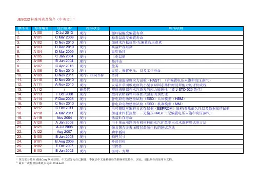
STANDARDUniversal Flash Storage (UFS) Card ExtensionVersion 1.0JESD220-2MARCH 2016JEDEC SOLID STATE TECHNOLOGY ASSOCIATIONNOTICEJEDEC standards and publications contain material that has been prepared, reviewed, and approved through the JEDEC Board of Directors level and subsequently reviewed and approved by the JEDEClegal counsel.JEDEC standards and publications are designed to serve the public interest through eliminatingmisunderstandings between manufacturers and purchasers, facilitating interchangeability and improvement of products, and assisting the purchaser in selecting and obtaining with minimum delay the proper product for use by those other than JEDEC members, whether the standard is to be used eitherdomestically or internationally.JEDEC standards and publications are adopted without regard to whether or not their adoption may involve patents or articles, materials, or processes. By such action JEDEC does not assume any liability to any patent owner, nor does it assume any obligation whatever to parties adopting the JEDEC standards orpublications.The information included in JEDEC standards and publications represents a sound approach to product specification and application, principally from the solid state device manufacturer viewpoint. Within the JEDEC organization there are procedures whereby a JEDEC standard or publication may be further processed and ultimately become an ANSI standard. No claims to be in conformance with this standardmay be made unless all requirements stated inthe standard are met.Special Legal Disclaimer: JEDEC has received information that certain patents or patent applications may be essential to this standard. However, as of the publication date of this standard, no statements regarding an assurance to license such patents or patent applications have been provided. JEDEC does not make any determination as to the validity or relevancy of such patents or patent applications. Anyone making use of the standard assumes all liability resulting from such use. JEDEC and its members disclaim any representation or warranty, express or implied, relating to the standard and its use. Inquiries, comments, and suggestions relative to the content of this JEDEC standard or publication should be addressed to JEDEC at the address below, or refer to under Standards and Documentsfor alternative contact information.Published by©JEDEC Solid State Technology Association 20163103 North 10th StreetSuite 240 SouthArlington, VA 22201-2107This document may be downloaded free of charge; however JEDEC retains the copyright on this material.By downloading this file the individual agrees not to charge for or resell the resulting material.PRICE: Contact JEDECPrinted in the U.S.A.All rights reservedPLEASE!DON’T VIOLATETHELAW!This document is copyrighted by JEDEC and may not bereproduced without permission.For information, contact:JEDEC Solid State Technology Association3103 North 10th StreetSuite 240 SouthArlington, VA 22201-2107or refer to under Standards-Documents/Copyright Information.JEDEC Standard No. 220-2 UNIVERSAL FLASH STORAGE (UFS) CARD EXTENSION, VERSION 1.0ContentsPage Foreword i Introduction i 1Scope 1 2Normative Reference 1 3Terms, and definitions 1 3.1Acronyms 1 3.2Terms and definitions 2 3.3Keywords 2 3.4Abbreviations 3 3.5Conventions 3 4Introduction 4 4.1Overview 4 4.2Functional Features 4 5UFS Card System Architecture 5 5.1Overview 5 5.2UFS Card Signals 5 6UFS Card Design 6 7Feature comParison of embedded UFS and UFS card 9 8UFS Card initialization 10 8.1Initialization Sequence 11 9Power Consumption 12 Annex A (informative) Host Guideline for UFS Card Detection 13 FiguresFigure 5.1 — UFS Card Block Diagram 5 Figure 6.1 — UFS Card Top View 6 Figure 6.2 — UFS Card Bottom View 7 Figure 6.3 — UFS Card Side View 8 Figure 8.1 — UFS Card Initialization 10 Figure 8.2 — UFS Card Initialization Sequence 11 TablesTable 5.1 — Signal Name and Definitions 5 Table 7.1 — Comparison of embedded UFS and UFS Card 9JEDEC Standard No. 220-2UNIVERSAL FLASH STORAGE (UFS) CARD EXTENSION, VERSION 1.0ForewordThis standard has been prepared by JEDEC. The purpose of this standard is to define a UFS card specification. This document will be extension of the UFS Standard, JESD220.IntroductionThe UFS device (embedded/removable) is a universal data storage and communication media. It is designed to cover a wide area of applications as smart phones, cameras, organizers, PDAs, digital recorders, MP3 players, internet tablets, electronic toys, etc.JEDEC Standard No. 220-2Page 1 UNIVERSAL FLASH STORAGE (UFS) CARD EXTENSION, VERSION 1.0 (From JEDEC Board Ballot JCB-16-12, formulated under the cognizance of the JC-64.1 Subcommittee on Electrical Specifications and Command Protocols (Item 133.69).)1ScopeThis standard specifies the characteristics of the UFS card electrical interface and the memory device. This document defines the added/modified features in UFS card compared to embedded UFS device. For other common features JESD220, UFS, Version 2.0, will be referenced.2Normative ReferenceThe following normative documents contain provisions that, through reference in this text, constitute provisions of this standard. For dated references, subsequent amendments to, or revisions of, any of these publications do not apply. However, parties to agreements based on this standard are encouraged to investigate the possibility of applying the most recent editions of the normative documents listed. For undated references, the latest edition of the normative document referred to applies.[MIPI-M-PHY], MIPI Alliance Specification for M-PHY SM Specification, Version 3.0[MIPI-UniPro], MIPI Alliance Specification for Unified Protocol (UniPro SM), Version 1.6[MIPI-DDB], MIPI Alliance Specification for Device Descriptor Block (DDB), Version[SAM], SCSI Architecture Model – 5 (SAM–5), Revision 05, 19 May 2010[SPC], T10 Specification: SCSI Primary Commands – 4 (SPC-4), Revision 27, 11 October 2010 [SBC], T10 Specification: SCSI Block Commands – 3 (SBC–3), Revision 24, 05 August 2010 [UFS], JEDEC JESD220B, Universal Flash Storage (UFS), Version 2.0[UFS], JEDEC JEP95, MO-320, UFS Card Form Factor3Terms, and definitionsFor the purpose of this standard, the terms and definitions given in the documents included in section 2“Normative Reference” and the following apply.3.1JEDEC Standard No. 220-2Page 23 Terms, and definitions (cont’d)3.2Terms and definitionsByte: An 8‐bit data value with most significant bit labeled as bit 7 and least significant bit as bit 0. Device: An addressable device on the UFS bus usually a target that contains at least one LUNHost: An addressable device on the UFS bus which is usually the main CPU that hosts the UFS bus3.3KeywordsSeveral keywords are used to differentiate levels of requirements and options, as follow:Can: A keyword used for statements of possibility and capability, whether material, physical, or causal (can equals is able to).Expected: A keyword used to describe the behavior of the hardware or software in the design models assumed by this standard. Other hardware and software design models may also be implemented. Ignored: A keyword that describes bits, bytes, quadlets, or fields whose values are not checked by the recipient.Mandatory: A keyword that indicates items required to be implemented as defined by this standard. May: A keyword that indicates a course of action permissible within the limits of the standard (may equals is permitted).Must: The use of the word must is deprecated and shall not be used when stating mandatory requirements; must is used only to describe unavoidable situations.Optional: A keyword that describes features which are not required to be implemented by this standard. However, if any optional feature defined by the standard is implemented, it shall be implemented as defined by the standard.Reserved: A keyword used to describe objects—bits, bytes, and fields—or the code values assigned to these objects in cases where either the object or the code value is set aside for future standardization. Usage and interpretation may be specified by future extensions to this or other standards. A reserved object shall be zeroed or, upon development of a future standard, set to a value specified by such a standard. The recipient of a reserved object shall not check its value. The recipient of a defined object shall check its value and reject reserved code values.Shall: A keyword that indicates a mandatory requirement strictly to be followed in order to conform to the standard and from which no deviation is permitted (shall equals is required to). Designers are required to implement all such mandatory requirements to assure interoperability with other products conforming to this standard.Should: A keyword used to indicate that among several possibilities one is recommended as particularly suitable, without mentioning or excluding others; or that a certain course of action is preferred but not necessarily required; or that (in the negative form) a certain course of action is deprecated but not prohibited (should equals is recommended that).Will: The use of the word will is deprecated and shall not be used when stating mandatory requirements; will is only used in statements of fact.JEDEC Standard No. 220-2Page 3 3 Terms, and definitions (cont’d)3.4Abbreviationsetc. - And so forth (Latin: et cetera)e.g. - For example (Latin: exempli gratia)i.e. - That is (Latin: id est)3.5ConventionsUFS specification follows some conventions used in SCSI documents since it adopts several SCSI standards.A binary number is represented in this standard by any sequence of digits consisting of only the Western-Arabic numerals 0 and 1 immediately followed by a lower-case b (e.g., 0101b). Spaces may be included in binary number representations to increase readability or delineate field boundaries (e.g., 0 0101 1010b).A hexadecimal number is represented in this standard by any sequence of digits consisting of only the Western-Arabic numerals 0 through 9 and/or the upper-case English letters A through F immediately followed by a lower-case h (e.g., FA23h). Spaces may be included in hexadecimal number representations to increase readability or delineate field boundaries (e.g.,B FD8C FA23h).A decimal number is represented in this standard by any sequence of digits consisting of only the Western-Arabic numerals 0 through 9 not immediately followed by a lower-case b or lower-case h (e.g.,25).A range of numeric values is represented in this standard in the form "a to z", where a is the first value included in the range, all values between a and z are included in the range, and z is the last value included in the range (e.g., the representation "0h to 3h" includes the values 0h, 1h, 2h, and 3h).When the value of the bit or field is not relevant, x or xx appears in place of a specific value.The first letter of the name of a Flag is a lower-case f (e.g., fMyFlag).The first letter of the name of a parameter included a Descriptor or the first letter of the name of an Attribute is:∙ a lower-case b if the parameter or the Attribute size is one byte (e.g., bMyParameter),∙ a lower-case w if the parameter or the Attribute size is two bytes (e.g., wMyParameter),∙ a lower-case d if the parameter or the Attribute size is four bytes (e.g., dMyParameter),∙ a lower-case q if the parameter or the Attribute size is eight bytes (e.g., qMyParameter).JEDEC Standard No. 220-2Page 44Introduction4.1OverviewThe JESD220 standard already defined some features for UFS card (removable). The UFS card uses same protocol as embedded UFS device, but it has few card specific requirements like power consumption.4.2Functional FeaturesUFS card functional features are similar to UFS embedded device. These include:∙Support for MIPI M-PHY PWM-Gear1. HS-Gear2 (optional) and HS-Gear3∙Supports Multiple partitions (LUNs) with partition Management∙Supports Multiple User Data Partition with Enhanced User Data Area options∙Reliable write operation∙Background operations∙Secure operations, Purge and Erase to enhance data security∙Write Protection options, including Permanent and Power-On Write Protection∙Task management operations∙Power management operations5UFS Card System Architecture5.1OverviewThe UFS card will use same protocol as embedded UFS device. There will not be any change in the overall system architecture of removable UFS card compared to embedded card.5.2UFS Card SignalsFigure 5.1 shows the conceptual drawing of UFS card.C/DFigure 5.1 — UFS Card Block Diagram6 UFS Card DesignThe UFS card will follow the shark design and a simplified pictorial representation is shown in Figure 6.1. Refer to JEP95, MO-320, for more detailed mechanical dimensions of Figure 6.1, Figure 6.2 and Figure 6.3.Figure 6.1 — UFS Card Top View6 UFS Card Design (cont’d)Figure 6.2 — UFS Card Bottom ViewPin 16 UFS Card Design (cont’d)Figure 6.3 — UFS Card Side View7Feature comparison of embedded UFS and UFS cardThe embedded UFS and UFS card follow the same protocol. But they will be used in different environment, the use cases will differ. So the UFS card shall have differences in supporting few features compared to embedded UFS. Table 7.1 shows the difference between embedded UFS and UFS card.The UFS card is supposed to be lite version of embedded UFS. So support for unnecessary gears shall be removed and UFS card shall supports only PWM-Gear1, HS-Gear2 (optional), and HS-Gear3. Similarly the UFS card shall support up to 1 lane compared to embedded UFS supports 2 lanes.VCCQ : The VCCQ pin is removed from UFS card to reduce the pin count. The UFS card vendors can use embed LDO to get the lower voltage which is aligned to their low voltage core from 3.3 V or 1.8 V source. Also as a power supply, 3.3 V and 1.8 V are mandatory considering the NAND controller, I/O logic. But 1.2 V can be generated wisely from 3.3 V or 1.8 V. So VCCQ pin (1.2 V) is not supported in UFS card.HW Reset : In case of embedded UFS the chip cannot be detached from the system PCB, so the HW reset pin is required.But in UFS card, card removal is possible, therefore the HW reset pin can be avoided. The minimizing of UFS card pin count can reduce the development and testing cost.Attributes : In embedded UFS the bRefClkFreq, bMaxNumOfRTT, and bMaxDataInSize, bMaxDataOutSize, bOutOfOrderDataEn and bActiveICCLevel attribute values are persistent. As the embedded UFS chip can’t be removed from the host, making these attributes value as persistent avoids re-initialization of these attributes. But in case of UFS card, it can be inserted in to different host which may want to use different values for these parameters. So in UFS card these attributes value shall reset to default value after every reset.8 UFS Card initializationThe UFS cad initialization follows same sequence as of eUFS. But as this is a removable device,VCC(3.3 V) and VCCQ2(1.8 V) may be provided after the UFS card is fully inserted into the card slot. The C/D pin may be used to support card insertion detection (refer to Annex A).Figure 8.1 — UFS Card InitializationCard Insertion UFS Link Start -up Process WaitNot Inserted Supply VCCQ2(1.8 V), VCC(3.3 V) Detect Card insertion in VoltageInserted8.1Initialization SequenceOnce the reset is done, the host will set the attributes to make the card compatible with the particular host.Figure 8.2 — UFS Card Initialization SequenceThe UFS card initialization is same as of embedded UFS, except the bRefClkFreq, bMaxNumOfRTT, bMaxDataInSize, bMaxDataOutSize,bOutOfOrderDataEn and bActiveICClevel attributes value will be set by the host. In embedded UFS these attributes will retain the value after the reset. But since the UFS card can be inserted into different host, these attribute values will be reset to their default value. The host has to set appropriate value before changing the mode to high speed mode.9Power ConsumptionThe UFS card shall be able to work in any host. Therefore power level which any UFS card can work shall be defined for host to provide required amount of power. So considering the removable card industry, the 1.6 watt would be needed for power consumption of the UFS card . The UFS card shall consume maximum 300 mA from VCC(3.3 V) and maximum 300 mA from VCCQ2(1.8 V).Annex A (informative) Host Guideline for UFS Card DetectionThe card detection (C/D) pin may be utilized to detect card insertion, by adding pull-up resistor to the C/D pin in the host-side C/D pin. When the UFS card is not inserted, host-side C/D pin shows non-zero voltage value. When the UFS card is inserted, host-side C/D pin shows zero voltage value because C/D pin of device is tied to ground.Figure A.1 — Host guideline for UFS Card DetectionUFS Card UFS HostStandard Improvement Form JEDECThe purpose of this form is to provide the Technical Committees of JEDEC with input from the industry regarding usage of the subject standard. Individuals or companies are invited to submit comments to JEDEC. All comments will be collected and dispersed to the appropriate committee(s).If you can provide input, please complete this form and return to:JEDECAttn: Publications Department3103 North 10th StreetSuite 240 SouthArlington, VA 22201-2107Fax: 703.907.7583Requirement, clause numberTest method number Clause numberUnclear Too RigidIn ErrorOther2. Recommendations for correction:3. Other suggestions for document improvement:Submitted byName: Phone: Company: E-mail: Address:City/State/Zip: Date:。