
MRSE-2-6UXPC中文资料
- 格式:pdf
- 大小:253.95 KB
- 文档页数:2
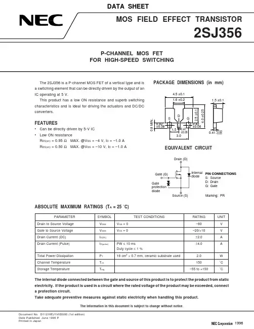
Document No. D11218EJ1V0DS00 (1st edition)Date Published June 1996 PPrinted in Japan19962TYPICAL CHARACTERISTICS (T A = 25 ˚C)DERATING FACTOR OF FORWARD BIAS SAFE OPERATING AREAd T - De r a t i n g F a c t o r -%2510080604020T A - Ambient Temperature - ˚CFORWARD BIAS SAFE OPERATING AREAI D - D r a i n C u r r e n t - A–0.5–10V DS - Drain to Source Voltage - V5075100125150–5–2–1–0.5–0.2–0.1–0.05–1–100–2–5–10–20–502SJ3563DRAIN TO SOURCE ON-STATE RESISTANCE vs.DRAIN CURRENT R D S (o n ) - D r a i n t o S o u r c e O n -S t a t e R e s i s t a n c e - Ω–0.00110.80.60.40.2I D - Drain Current - ADRAIN TO SOURCE ON-STATE RESISTANCE vs.GATE TO SOURCE VOLTAGE R D S (o n ) - D r a i n t o S o u r c e O n -S t a t e R e s i s t a n c e - Ω010.80.60.40.2V GS - Gate to Source Voltage - V–10–0.01–0.1–1–20–2–4–6–8–10–12–14–16–18DRAIN CURRENT vs.DRAIN TO SOURCE VOLTAGEI D - D r a i n C u r r e n t - A–5V DS - Drain to Source Voltage - V TRANSFER CHARACTERISTICS I D - D r a i n C u r r e n t - A–1–10V GS - Gate to Source Voltage - VFORWARD TRANSFER ADMITTANCE vs.DRAIN CURRENT |y f s | - F o r w a r d T r a n s f e r A d m i t t a n c e - S–0.000110I D - Drain Current - ADRAIN TO SOURCE ON-STATE RESISTANCE vs.DRAIN CURRENT R D S (o n ) - D r a i n t o S o u r c e O n -S t a t e R e s i s t a n c e - Ω–0.0011.5I D - Drain Current - A–1–2–3–4–5–4–3–2–1–2–3–4–1–0.1–0.01–0.001–0.0001–0.0000110.10.010.001–0.001–0.01–0.1–110.5–0.01–0.1–1–104TRANSIENT THERMAL RESISTANCE vs. PULSE WIDTHrth(j-a)-TransientThermalResistance-˚C/W1 m1 000100101PW - Pulse Width - s10 m100 m110100Single pulseUsing ceramic substrate of7.5 cm2× 0.7 mmSOURCE TO DRAIN DIODEFORWARD VOLTAGEISD-DiodeForwardCurrent-A–0.2–10–1–0.1–0.01–0.001–0.0001V SD - Source to Drain Voltage - VCAPACITANCE vs.DRAIN TO SOURCE VOLTAGECiss,Coss,Crss-Capacitance-pF–110 0001 00010010V DS - Drain to Source Voltage - V SWITCHING CHARACTERISTICStd(on),tr,td(off),tf-SwitchingTime-ns1 00010010I D - Drain Current - AREVERSE RECOVERY TIME vs.DIODE FORWARD CURRENTtrr-ReverseRecoveryTime-ns–0.051 00010010I F - Diode Forward Current -A–1.2–0.4–0.6–0.8–1.0V GS = 0Pulsed–10–100–1–10–10–0.1–0.5–1–5V GS = 0di/dt = 50 A/ sµREFERENCEDocument Name Document No.NEC semiconductor device reliability/quality control system TEI-1202Quality grade on NEC semiconductor devices IEI-1209 Semiconductor device mounting technology manual C10535EGuide to quality assurance for semiconductor devices MEI-1202 Semiconductor selection guide X10679E5[MEMO]No part of this document may be copied or reproduced in any form or by any means without the prior written consent of NEC Corporation. NEC Corporation assumes no responsibility for any errors which may appear in this document.NEC Corporation does not assume any liability for infringement of patents, copyrights or other intellectual property rights of third parties by or arising from use of a device described herein or any other liability arising from use of such device. No license, either express, implied or otherwise, is granted under any patents, copyrights or other intellectual property rights of NEC Corporation or others.While NEC Corporation has been making continuous effort to enhance the reliability of its semiconductor devices, the possibility of defects cannot be eliminated entirely. To minimize risks of damage or injury to persons or property arising from a defect in an NEC semiconductor device, customer must incorporate sufficient safety measures in its design, such as redundancy, fire-containment, and anti-failure features.NEC devices are classified into the following three quality grades:“Standard“, “Special“, and “Specific“. The Specific quality grade applies only to devices developed based ona customer designated “quality assurance program“ for a specific application. The recommended applicationsof a device depend on its quality grade, as indicated below. Customers must check the quality grade of each device before using it in a particular application.Standard:Computers, office equipment, communications equipment, test and measurement equipment, audio and visual equipment, home electronic appliances, machine tools, personal electronicequipment and industrial robotsSpecial:Transportation equipment (automobiles, trains, ships, etc.), traffic control systems, anti-disaster systems, anti-crime systems, safety equipment and medical equipment (not specifically designedfor life support)Specific:Aircrafts, aerospace equipment, submersible repeaters, nuclear reactor control systems, life support systems or medical equipment for life support, etc.The quality grade of NEC devices in “Standard“ unless otherwise specified in NEC's Data Sheets or Data Books.If customers intend to use NEC devices for applications other than those specified for Standard quality grade, they should contact NEC Sales Representative in advance.Anti-radioactive design is not implemented in this product.M4 94.11。

RAD750®6U CompactPCI single-board computerThe 6U CompactPCI singleboard computer ,available in seven configurations, employs the PowerPC RAD750® microprocessor, the radiationhardened version of the IBM PowerPC750 microprocessor. The companion Power PCI Bridge ASIC provides access to the memory and the PCI version 2.2 backplane bus. Key features• E xample startup ROM and VxWorks boardsupport package provided for all hardware configurations• G reen Hills Software’s INTEGRITY real-time operating system can serve as an alternate board support package• Hardware reference manuals and software user guide provided • S oftware developed for the RAD6000® processor is easily ported to RAD750® computers• A ll compilers currently available for the commercial PowerPC 750 microprocessor are fully compatible with the RAD750®• O perating systems for PowerPC 750-based computers are easily ported to RAD750® computers- VXWorks and INTEGRITY operating systems available• Virtutech offers a RAD750® simulatorSupports variable memory configurations:• S RAM:– 16-MB standard– Options from 4 MB to 48 MB and ECC – Device-sparing• S UROM:– 64 kB and ECC– EEPROM for engineering units (256 kB to 1 MB) – PROM for flight units (64 kB to 256 kB)• E EPROM:–4 MB and ECCSpecifications Form factor CompactPCI 6U (233 mm x 160 mm) CompactPCI 6U-220 (233mm x 220mm)Weight: 1000 to 1220 grams, varies with memory Memory SRAM: 4 to 48 MBEEPROM: 4 MBRadiation-hardness Total dose: >100 Krad (Si)SEU: 1.9 E-4 errors/card-day (90 percent W. C. GEO) varies with orbit Latchup-immunePerformance >260 Dhrystone 2.1 MIPS at 132 MHz4.3 SPECint95 4.6 SPECfp95 at 132 MHzPower supply – 5 volts ± 10 percent and 3.3 volts ± 5 percent (2.5 volts generated via onboard regulator)Power dissipation 11 to 14 wattsRail temperature range-28 degrees celsius to +70 degrees celsiusFor more information contact:BAE Systems9300 Wellington RoadManassas, Virginia 20110-4122 T: 571 364 7777W: /spaceproducts Cleared for open publication on 07/08Disclaimer and copyrightBAE Systems reserves the right to restrict component sales based on application and volume. Please contact the factory for more information.This document gives only a general description of the product(s) and service(s) and, except where expressly provided otherwise, shall not form any part of any contract. From time to time, changes may be made in the products or the conditions of supply.BAE Systems reserves the right to restrict component sales based on application and volume. Please contact the factory for more information. BAE SYSTEMS is a registered trademark of BAE Systems plc.©2018 BAE Systems. All rights reserved.CS-16-F77BAE Systems | RAD750® 6U CompactPCI single-board computerRAD750 6U flexible architectureRAD750® family of productsRAD750® radiation-hardened PowerPC microprocessor RAD750® 6U CompactPCI single-board computerRAD750® 6U CompactPCI extended single-board computerRAD750® 3U CompactPCI single-board computerRAD750® space computers Virtutech Simics virtual platform RAD750® custom single-board computers。

三菱 通用 AC伺服SSCNETⅢ/H接口型号MR-JE-_B伺服放大器技术资料集使用前请务必阅读。
在安装、运行、维护及检查前,请务必熟读本技术资料集、使用手册及相关资料,以便正确使用。
请在熟读机器的相关知识、安全信息及注意事项的所有内容后进行使用。
本技术资料集中,分为“危险”与“注意”两类安全注意事项。
危险 操作错误时,可能引起危险,造成死亡或重伤。
注意 操作错误时,可能引起危险,造成中度伤害、轻度伤害或财产损失。
此外,即使注意事项中记载的内容,有时也有造成严重后果的可能性。
两者所记均为重要内容,请务必遵守。
禁止及强制图表的表示内容如下所示。
表示禁止(严禁采取的行为)。
比如“严禁烟火”为。
表示强制(必须采取的行为)。
比如需要接地为。
在本技术资料集中,对不会造成财产损失的注意事项及其它功能等的注意事项作为“要点”进行区分。
仔细阅读本手册后请妥善保管,以便使用者可以随时取阅。
1.防止触电危险因为有触电的危险,所以请在关闭电源并经过15分钟以上,请确认充电指示灯熄灭后再进行接线作业或检查。
而且,确认充电指示灯是否熄灭时,请务必在伺服放大器的正面进行。
伺服放大器及伺服电机必须确保接地良好。
接线作业或检查应由专业技术人员进行。
伺服放大器及伺服电机请在安装后再接线。
否则会造成触电。
请勿用湿手操作开关。
否则会造成触电。
请勿损伤电缆、对其施加过大应力、在其上放置重物或挤压等。
否则会造成触电。
为了防止触电,请务必将伺服放大器的保护接地(PE)端子(带有符号的端子)连接到控制柜的保护接地(PE)上。
使用漏电断路器(RCD)时,请选用B型。
为避免触电,请在电源端子的连接部进行绝缘处理。
2.防止火灾注意请将伺服放大器、伺服电机、再生电阻安装在不可燃物上。
直接安装在可燃物上或安装在靠近可燃物的地方,可能会造成冒烟及火灾。
在电源和伺服放大器的电源(L1・L2・L3)间请务必连接电磁接触器,在伺服放大器的电源侧形成可以切断电源的结构。