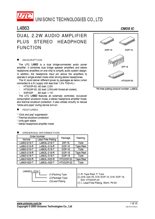
General DescriptionThe MAX1117/MAX1118/MAX1119 low-power, 8-bit,dual-channel, analog-to-digital converters (ADCs) fea-ture an internal track/hold (T/H) voltage reference (MAX1117/MAX1119), clock, and serial interface. The MAX1118 is specified from +2.7V to +5.5V and con-sumes only 135µA at 100ksps. The MAX1117 is speci-fied from +2.7V to +3.6V, and the MAX1119 is specified from +4.5V to +5.5V, each consumes only 175µA at 100ksps.The full-scale analog input range is determined by the internal reference of +2.048V (MAX1117) or +4.096V (MAX1119), or by an externally applied reference rang-ing from +1V to V DD (MAX1118). All devices feature an automatic shutdown mode that reduces supply current to <1µA when the device is not in use. The 3-wire serial interface directly connects to SPI ™, QSPI ™, and M CROW RE™ devices without external logic.Conversions up to 100ksps are performed using an internal clock.The MAX1117/MAX1118/MAX1119 are available in an 8-pin SOT23 package with a footprint that is only 11%of an 8-pin plastic DIP.________________________ApplicationsLow-Power, Handheld Portable Devices System DiagnosticsBattery-Powered Test Equipment Solar-Powered Remote Systems Receive Signal Strength Indicators4mA to 20mA Powered Remote Data Acquisition SystemsFeatureso Single Supply+2.7V to +3.6V (MAX1117)+2.7V to +5.5V (MAX1118)+4.5V to +5.5V (MAX1119)o Internal Track/Hold: 100kHz Sampling Rate o Internal Reference+2.048V (MAX1117)+4.096V (MAX1119)o Reference Input Range: 0 to V DD (MAX1118)o SPI/QSPI/MICROWIRE-Compatible Serial Interface o Small 8-Pin SOT23 Package o Automatic Power-Down o Analog Input Range: 0 to V REFo Low Power175µA at 100ksps (typ) (MAX1117/MAX1119)135µA at 100ksps (typ) (MAX1118)18µA at 10ksps (typ)1µA (typ) in Power-Down ModeMAX1117/MAX1118/MAX1119Single-Supply, Low-Power, 2-Channel, Serial 8-Bit ADCs________________________________________________________________Maxim Integrated Products 1Pin Configuration19-1857; Rev 0; 11/00Ordering InformationSPI/QSPI are trademarks of Motorola, Inc.MICROWIRE is a trademark of National Semiconductor, Corp.Functional Diagram appears at end of data sheet.For price, delivery, and to place orders,please contact Maxim Distribution at 1-888-629-4642,or visit Maxim’s website at .M A X 1117/M A X 1118/M A X 1119Single-Supply, Low-Power, 2-Channel, Serial 8-Bit ADCs 2_______________________________________________________________________________________ABSOLUTE MAXIMUM RATINGSELECTRICAL CHARACTERISTICS(V DD = +2.7V to +3.6V (MAX1117), V DD = +4.5V to +5.5V (MAX1119), V DD = REF = +2.7V to +5.5V (MAX1118),T A = T MIN to T MAX ,unless otherwise noted.)Stresses beyond those listed under “Absolute Maximum Ratings” may cause permanent damage to the device. These are stress ratings only, and functional operation of the device at these or any other conditions beyond those indicated in the operational sections of the specifications is not implied. Exposure to absolute maximum rating conditions for extended periods may affect device reliability.V DD to GND...........................................................-0.3V to +6.0V CH0,CH1, REF to GND...............................-0.3V to (V DD + 0.3V)Digital Output to GND................................-0.3V to (V DD + 0.3V)Digital Input to GND..............................................-0.3V to +6.0V Maximum Current into Any Pin.........................................±50mA Continuous Power Dissipation (T A = +70°C)8-Pin SOT23 (derate 8.9mW/°C above +70°C)............714mWOperating Temperature RangeMAX1117EKA..................................................-40°C to + 85°C MAX1118EKA..................................................-40°C to + 85°C MAX1119EKA..................................................-40°C to + 85°C Storage Temperature Range.............................-60°C to +150°C Lead Temperature (soldering, 10s).................................+300°CELECTRICAL CHARACTERISTICS (continued)MAX1117/MAX1118/MAX1119Single-Supply, Low-Power, 2-Channel, Serial 8-Bit ADCs (V DD= +2.7V to +3.6V (MAX1117), V DD= +4.5V to +5.5V (MAX1119), V DD= REF = +2.7V to +5.5V (MAX1118),T A= T MIN to T MAX,unless otherwise noted.) Array_______________________________________________________________________________________3Typical Operating Characteristics(V DD = +3V (MAX1117), V DD = +5V (MAX1119), V DD = V REF = +3V (MAX1118), f SCLK = 5MHz, f SAMPLE = 100ksps, C LOAD = 100pF,T A = +25°C, unless otherwise noted.)M A X 1117/18/19 t o c 01-1.0-0.4-0.6-0.8-0.200.20.40.60.81.0010050150200250300INTEGRAL NONLINEARITYvs.OUTPUT CODEOUTPUT CODEI N L (L S B )10050150200250300DIFFERENTIAL NONLINEARITYvs.OUTPUT CODEM A X 1117/18/19 t o c 02OUTPUT CODED N L (L S B )-1.0-0.4-0.6-0.8-0.200.20.40.60.81.00.20.10.40.30.60.50.7SHUTDOWN SUPPLY CURRENTvs. SUPPLY VOLTAGEM A X 1117/18/19 t o c 03SUPPLY VOLTAGE (V)S H U T D O W N C U R R E N T (µA )2.53.54.55.50.10.010.1110100MAX1118SUPPLY CURRENT vs. CONVERSION RATE1.0CONVERSION (ksps)S U P P L Y C U R R E N T (µA )100.010.00204060801101201401602.53.54.55.5MAX1118SUPPLY CURRENT vs. SUPPLY VOLTAGESUPPLY VOLTAGE (V)S U P P L Y C U R R E N T (µA )50100150-40-1510356085MAX1118 SUPPLY CURRENTvs. TEMPERATURETEMPERATURE (°C)S U P P L Y C U R R E N T (µA )M A X 1117/M A X 1118/M A X 1119Single-Supply, Low-Power, 2-Channel, Serial 8-Bit ADCs 4_______________________________________________________________________________________Note 1:Relative accuracy is the deviation of the analog value at any code from its theoretical value after the full-scale range and off-set have been calibrated.Note 2:Input = 0, with logic input levels of 0 and V DD .ELECTRICAL CHARACTERISTICS (continued)(V DD = +2.7V to +3.6V (MAX1117), V DD = +4.5V to +5.5V (MAX1119), V DD = REF = +2.7V to +5.5V (MAX1118),T A = T MIN to T MAX ,unless otherwise noted.)MAX1117/MAX1118/MAX1119Single-Supply, Low-Power, 2-Channel, Serial 8-Bit ADCs_______________________________________________________________________________________5Typical Operating Characteristics (continued)(V DD = +3V (MAX1117), V DD = +5V (MAX1119), V DD = V REF = +3V (MAX1118), f SCLK = 5MHz, f SAMPLE = 100ksps, C LOAD = 100pF,T A = +25°C, unless otherwise noted.)0.10.010.1110100MAX1117/MAX11191.0CONVERSION (ksps)S U P P L Y C U R R E N T (µA )100.010.0100501502002.53.54.55.5MAX1117/MAX1119 SUPPLY CURRENTvs. SUPPLY VOLTAGESUPPLY VOLTAGE (V)S U P P L Y C U R R E N T (µA )010050150200-40-1535106085MAX1117/MAX1119SUPPLY CURRENT vs. TEMPERATURETEMPERATURE (V)S U P P L Y C U R R E N T (µA )5.05.25.35.15.45.52.53.54.55.5CONVERSION TIME vs. SUPPLY VOLTAGEM A X 1117/18/19 t o c 11SUPPLY VOLTAGE (V)C O N V E R S I O N T I M E(µs )5.05.25.35.15.45.5-40-1510356085CONVERSION TIME vs. TEMPERATURETEMPERATURE (°C)C O N V E R S I O N T I M E (µs )-120-80-100-60-40-200020k 10k 30k 40k 50kFFT PLOTM A X 1117/18/19 t o c 13ANALOG INPUT FREQUENCY (Hz)A M P L I T U D E (dB )-0.2-0.40.20.42.54.53.55.5MAX1118GAIN ERROR vs. SUPPLY VOLTAGESUPPLY VOLTAGE (V)G A I N E R R O R (L SB )-0.5-0.2-0.3-0.4-0.100.10.20.30.40.5-4010-15356085MAX1118GAIN ERROR vs. TEMPERATURETEMPERATURE (°C)G A I N E R R O R (L S B)-1.0-0.6-0.4-0.8-0.2014532MAX1118GAIN ERROR vs. REFERENCE VOLTAGEREFERENCE VOLTAGE (V)G A I N E R R O R (L S B )M A X 1117/M A X 1118/M A X 1119Single-Supply, Low-Power, 2-Channel, Serial 8-Bit ADCs 6_______________________________________________________________________________________Typical Operating Characteristics (continued)(V DD = +3V (MAX1117), V DD = +5V (MAX1119), V DD = V REF = +3V (MAX1118), f SCLK = 5MHz, f SAMPLE = 100ksps, C LOAD = 100pF,T A = +25°C, unless otherwise noted.)-0.50-0.10.1-0.2-0.3-0.40.30.20.40.52.53.04.05.04.53.5 5.5MAX1118OFFSET ERROR vs. SUPPLY VOLTAGESUPPLY VOLTAGE (V)O F F S E T E R R O R (L S B )-0.50-0.10.1-0.2-0.3-0.40.30.20.40.5-40356010-1585MAX1118OFFSET ERROR vs. TEMPERATURETEMPERATURE (°C)O F F S E T E R R O R (L S B )-0.5-0.10.1-0.30.3-0.400.2-0.20.40.514532MAX1118OFFSET ERROR vs. REFERENCE VOLTAGEREFERENCE VOLTAGE (V)O F F S E T E R R O R (L S B )SUPPLY VOLTAGE (V)00.60.80.40.21.21.01.42.54.53.55.5MAX1117/MAX1119GAIN ERROR vs. SUPPLY VOLTAGEG A I N E R R O R (%F S R )-2.000.5-1.0-0.5-1.51.51.02.0-40603510-1585MAX1117/MAX1119GAIN ERROR vs. TEMPERATURETEMPERATURE (°C)G A I N E R R O R (%F S R )-120-80-100-60-40-200020k 10k30k 40k 50kFFT PLOTANALOG INPUT FREQUENCY (Hz)A M P L I T U D E (dB )f SAMPLE = 100kHz f IN = 25.1kHzA IN = 0.9 x V REFp-p-0.50-0.10.1-0.2-0.3-0.40.30.20.40.52.53.04.05.04.53.55.5MAX1117/MAX1119OFFSET ERROR vs. SUPPLY VOLTAGESUPPLY VOLTAGE (V)O F F S E T E R R O R (L S B )-0.50-0.10.1-0.2-0.3-0.40.30.20.40.5-40-1560351085MAX1117/MAX1119OFFSET ERROR vs. TEMPERATURETEMPERATURE (°C)O F F S E T E R R O R (L S B )MAX1117/MAX1118/MAX1119Single-Supply, Low-Power, 2-Channel, Serial 8-Bit ADCs_______________________________________________________________________________________7Typical Operating Characteristics (continued)(V DD = +3V (MAX1117), V DD = +5V (MAX1119), V DD = V REF = +3V (MAX1118), f SCLK = 5MHz, f SAMPLE = 100ksps, C LOAD = 100pF,T A = +25°C, unless otherwise noted.)010.5%7.0%3.5%17.5%21.0%14.0%3.9804.020 4.1404.1004.060 4.180REFERENCE VOLTAGE vs. NUMBER OF PIECESM A X 1115 t o c 25REFERENCE VOLTAGE (V)010.5%7.0%3.5%17.5%21.0%14.0%1.9822.008 2.0862.0602.034 2.112REFERENCE VOLTAGE vs. NUMBER OF PIECESM A X 1117/18/19 t o c 26REFERENCE VOLTAGE (V)M A X 1117/M A X 1118/M A X 1119Single-Supply, Low-Power, 2-Channel, Serial 8-Bit ADCs 8_______________________________________________________________________________________Figure 3. Typical Operating CircuitFigure 4. Equivalent Input CircuitDetailed DescriptionThe MAX1117/MAX1118/MAX1119 ADCs use a suc-cessive-approximation conversion technique and input T/H circuitry to convert an analog signal to an 8-bit digi-tal output. The SPI/QSPI/MICROWIRE compatible inter-face directly connects to microprocessors (µPs) without additional circuity (Figure 3).Track/HoldThe input architecture of the ADC is illustrated in Figure 4’s equivalent-input circuit and is composed of the T/H,the input multiplexer, the input comparator, the switched capacitor DAC, and the auto-zero rail.The acquisition interval begins with the falling edge of CNVST. During the acquisition interval, the analoginputs (CH0, CH1) are connected to the holding capac-itor (C HOLD ). Once the acquisition has completed, the T/H switch opens and C HOLD is connected to GND,retaining the charge on C HOLD as a sample of the sig-nal at the analog input.Sufficiently low source impedance is required to ensure an accurate sample. A source impedance <1.5k Ωis recommended for accurate sample settling. A 100pF capacitor at the ADC inputs will also improve the accu-racy of an input sample.Conversion ProcessThe MAX1117/MAX1118/MAX1119 conversion process is internally timed. The total acquisition and conversion process takes <7.5µs. Once an input sample has been acquired, the comparator ’s negative input is then con-Figure 1. Load Circuits for Enable TimeFigure 2. Load Circuits for Disable Timenected to an autozero supply. Since the device requires only a single supply, the negative input of the comparator is set to equal V DD/2. The capacitive DAC restores the positive input to V DD/2 within the limits of 8-bit resolution. This action is equivalent to transferring a charge Q IN= 16pF x V IN from C HOLD to the binary-weighted capacitive DAC, which in turn forms a digital representation of the analog-input signal.Input Voltage Range I nternal protection diodes that clamp the analog input to V DD and GND allow the input pins (CH0, CH1) to swing from (GND - 0.3V) to (V DD+ 0.3V) without dam-age. However, for accurate conversions, the inputs must not exceed (V DD+ 50mV) or be less than (GND -50mV).Input Bandwidth The ADC’s input tracking circuitry has a 4MHz small-signal bandwidth, so it is possible to digitize high-speed transient events and measure periodic signals with bandwidths exceeding the ADC’s sampling rate by using undersampling techniques. To avoid high-fre-quency signals being aliased into the frequency band of interest, anti-alias filtering is recommended.Serial Interface The MAX1117/MAX1118/MAX1119 have a 3-wire serial interface. The CNVST and SCLK inputs are used to control the device, while the three-state DOUT pin is used to access the conversion results.The serial interface provides connection to microcon-trollers (µCs) with SPI, QSPI, and MI CROWI RE serial interfaces at clock rates up to 5MHz. The interface sup-ports either an idle high or low SCLK format. For SPI and QSPI, set CPOL = CPHA = 0 or CPOL = CPHA = 1 in the SPI control registers of the µC. Figure 5 shows the MAX1117/MAX1118/MAX1119 common serial-inter-face connections. See Figures 6a–6d for details on the serial interface timing and protocol.Digital Inputs and Outputs The MAX1117/MAX1118/MAX1119 perform conver-sions using an internal clock. This frees the µP from the burden of running the SAR conversion clock and allows the conversion results to be read back at the µP’s con-venience at any clock rate up to 5MHz.The acquisition interval begins with the falling edge of CNVST. CNVST can idle between conversions in either a high or low state. If idled in a low state, CNVST must be brought high for at least 50ns, then brought low to initiate a conversion. To select CH1 for conversion, the CNVST pin must be brought high and low for a second time (Figures 6c and 6d).After CNVST is brought low, allow 7.5µs for the conver-sion to be completed. While the internal conversion is in progress, DOUT is low. The MSB is present at the DOUT pin immediately after conversion is completed. The conversion result is clocked out at the DOUT pin and is coded in straight binary (Figure 7). Data is clocked out at SCLK’s falling edge in MSB-first format at rates up to 5MHz. Once all data bits are clocked out, DOUT goes high impedance (100ns to 500ns after the rising edge) of the eighth SCLK pulse.Figure 5. Common Serial-Interface ConnectionsMAX1117/MAX1118/MAX1119Single-Supply, Low-Power, 2-Channel, Serial 8-Bit ADCs_______________________________________________________________________________________9M A X 1117/M A X 1118/M A X 1119Single-Supply, Low-Power, 2-Channel, Serial 8-Bit ADCs 10______________________________________________________________________________________During the conversion process, SCLK is ignored. Only after a conversion is complete will SCLK cause serial data to be output. Falling edges on CNVST, during an active conversion process, interrupt the current conver-sion and cause the input multiplexer to switch to CH1.To reinitiate a conversion on CH0, it is necessary toallow for a conversion to be complete and all of the data to be read out. Once a conversion has been com-pleted, the MAX1117/MAX1118/MAX1119 will go into AutoShutdown ™ mode (<1µA typ) until the next conver-sion is initiated.Figure 6a. Conversion and Interface Timing, Conversion on CH0 with SCLK Idle LowFigure 6b. Conversion and Interface Timing, Conversion on CH0 with SCLK Idle HighAutoShutdown is a trademark of Maxim Integrated Products.MAX1117/MAX1118/MAX1119Single-Supply, Low-Power, 2-Channel, Serial 8-Bit ADCsFigure 6c. Conversion and Interface Timing, Conversion on CH1 with SCLK Idle Low ArrayFigure 6d. Conversion and Interface Timing, Conversion on CH1 with SCLK Idle High______________________________________________________________________________________11M A X 1117/M A X 1118/M A X 1119Single-Supply, Low-Power, 2-Channel, Serial 8-Bit ADCs 12______________________________________________________________________________________Applications InformationPower-On ResetWhen power is first applied, the MAX1117/MAX1118/MAX1119 are in AutoShutdown state (<1µA typ). A conver-sion can be started by toggling CNVST high to low. Powering up the MAX1117/MAX1118/MAX1119 with CNVST low will not start a conversion. Conversions initiated prior to the external reference settling (MAX1118) will result in errors.Thus, it is necessary to allow the external reference to stabi-lize prior to initiating a conversion.AutoShutDown and Supply CurrentRequirementsThe MAX1117/MAX1118/MAX1119 are designed to automatically shutdown once a conversion is complete without any external control. An input sample and con-version process will typically take 5µs to complete, dur-ing which time the supply current to the analog sections of the device is fully on. All analog circuitry is shutdown after a conversion completes, which results in a supply current of <1µA (see Shutdown Current vs.Supply Voltage Plot in the Typical Operating Characteristics ). The digital conversion result is main-tained in a static register and is available for access through the serial interface at any time.The power consumption consequence of this architec-ture is dramatic when relatively slow conversion rates are needed. For example, at a conversion rate of 10ksps, the average supply current for the MAX1117 is15µA, while at 1ksps it drops to 1.5µA and at 0.1ksps it is just 0.3µA, or a miniscule 1µW of power consumption (see Average Supply Current vs. Conversion Rate Plot in the Typical Operating Characteristics ).External Voltage Reference (MAX1118)Connect an external reference between +1V and V DD at the REF pin. The DC input impedance at REF is extremely high, consisting of leakage current only (10nA typ). During a conversion, the reference must be able to deliver up to 20µA average load current and have an output impedance of 100Ωor less. If the refer-ence has higher output impedance or is noisy, bypass it close to the REF pin with a 10nF or larger capacitor.Transfer FunctionFigure 7 depicts the input/output transfer function.Output coding is binary with a +2.048V reference 1LSB = 8mV (V REF /256).Layout, Grounding, BypassingFor best performance, the board layout should ensure that digital and analog signal lines are separated from each other. Do not run analog and digital (especially clock) lines parallel to one another or run digital lines underneath the ADC package.Figure 8 shows the recommended system-ground con-nections. A single-point analog ground (star-ground point) should be established at the ADC ground.Connect all analog grounds to the star ground. The ground return to the power supply for the star groundFigure 7. Input/Output Transfer FunctionFigure 8. Power-Supply ConnectionsMAX1117/MAX1118/MAX1119Single-Supply, Low-Power, 2-Channel, Serial 8-Bit ADCs______________________________________________________________________________________13should be low impedance and as short as possible for noise-free operation.High-frequency noise in the V DD power supply may affect the comparator in the ADC. Bypass the supply to the star ground with a 0.1µF capacitor close to the V DD pin of the MAX1117/MAX1118/MAX1119. Minimize capacitor lead lengths for best supply-noise rejection. If the power supply is noisy, a 1µF capacitor in conjunc-tion with a 10Ωseries resistor can be connected to form a lowpass filter.Chip InformationTRANSISTOR COUNT: 2000PROCESS: BiCMOSFunctional DiagramsM A X 1117/M A X 1118/M A X 1119Single-Supply, Low-Power, 2-Channel, Serial 8-Bit ADCs Maxim cannot assume responsibility for use of any circuitry other than circuitry entirely embodied in a Maxim product. No circuit patent licenses are implied. Maxim reserves the right to change the circuitry and specifications without notice at any time.14____________________Maxim Integrated Products, 120 San Gabriel Drive, Sunnyvale, CA 94086 408-737-7600©2000 Maxim Integrated ProductsPrinted USAis a registered trademark of Maxim Integrated Products.Package Information。