S-80716AL-AD-X中文资料
- 格式:pdf
- 大小:299.09 KB
- 文档页数:42
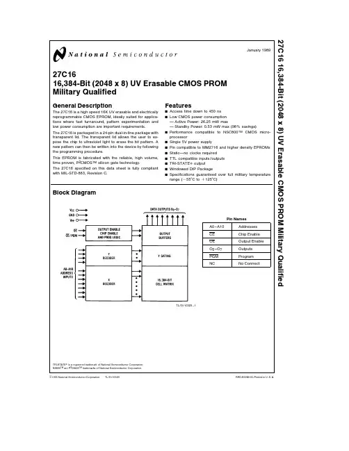
TL D 1032927C16 16 384-Bit (2048 x 8) UV Erasable CMOS PROM Military QualifiedJanuary1989 27C1616 384-Bit(2048x8)UV Erasable CMOS PROMMilitary QualifiedGeneral DescriptionThe27C16is a high speed16K UV erasable and electricallyreprogrammable CMOS EPROM ideally suited for applica-tions where fast turnaround pattern experimentation andlow power consumption are important requirementsThe27C16is packaged in a24-pin dual-in-line package withtransparent lid The transparent lid allows the user to ex-pose the chip to ultraviolet light to erase the bit pattern Anew pattern can then be written into the device by followingthe programming procedureThis EPROM is fabricated with the reliable high volumetime proven P2CMOS TM silicon gate technologyThe27C16specified on this data sheet is fully compliantwith MIL-STD-883 Revision CFeaturesY Access time down to450nsY Low CMOS power consumptionActive Power 26 25mW maxStandby Power 0 53mW max(98%savings)Y Performance compatible to NSC800TM CMOS micro-processorY Single5V power supplyY Pin compatible to MM2716and higher density EPROMsY Static no clocks requiredY TTL compatible inputs outputsY TRI-STATE outputY Windowed DIP PackageY Specifications guaranteed over full military temperaturerange(b55 C to a125 C)Block DiagramTL D 10329–1Pin NamesA0–A10AddressesCE Chip EnableOE Output EnableO0–O7OutputsPGM ProgramNC No ConnectTRI-STATE is a registered trademark of National Semiconductor CorporationNS800TM are P2CMOS TM trademarks of National Semiconductor CorporationC1995National Semiconductor Corporation RRD-B30M105 Printed in U S AConnection Diagram27C25627C12827C6427C32 272562712827642732V PP V PP V PPA12A12A12A7A7A7A7 A6A6A6A6 A5A5A5A5 A4A4A4A4 A3A3A3A3 A2A2A2A2 A1A1A1A1 A0A0A0A0 O0O0O0O0 O1O1O1O1 O2O2O2O2 GND GND GND GND Dual-In-Line Package27C16QTL D 10329–2Top View27C3227C6427C12827256273227642712827256V CC V CC V CCPGM PGM A14V CC NC A13A13A8A8A8A8A9A9A9A9A11A11A11A11OE V PP OE OE OEA10A10A10A10CE CE CE CEO7O7O7O7O6O6O6O6O5O5O5O5O4O4O4O4O3O3O3O3Note Socket compatible EPROM pin configurations are shown in the blocks adjacent to the27C16pinsMilitary Temp Range(b55 C to a125 C)V CC e5V g10%Parameter Order Number Access Time(ns)27C16Q450 88345027C16Q550 8835502Absolute Maximum Ratings(Note1) Temperature Under Bias b55 C to a125 C Storage Temperature b65 C to a125 C All Input Voltages withRespect to Ground a6 5V to b0 3V All Output Voltages withRespect to Ground(Note11)V CC a0 3V to GND b0 3V V PP Supply Voltagewith Respect to Groundduring Programming a26 5V to b0 3V Power Dissipation1 0W Lead Temperature(Soldering 10Seconds)300 C Operating Conditions(Note9) Temperature Range(T case)b55 C to a125 C V CC Power Supply(Notes2and3)5V a10% V PP Power Supply(Note3)V CCREAD OPERATIONDC Electrical CharacteristicsSymbol Parameter Conditions MinTypMax Units (Note4)I LI Input Load Current V IN e V CC or V IL10m A I LO Output Leakage Current V OUT e V CC or V IL CE e V IH10m A I CC1V CC Current(Active)OE e CE e V IL f e1MHz230mA (Note3)TTL Inputs Inputs e V IH or V IL I O e0mAI CC2V CC Current(Active)OE e CE e V IL f e1MHz125mA(Note3)CMOS Inputs Inputs e V CC or GND I O e0mAI CCSB1V CC Current(Standby)CE e V IH0 11mATTL InputsI CCSB2V CC Current(Standby)CE e V CC0 010 1mACMOS InputsV IL Input Low Voltage b0 10 8V V IH Input High Voltage2 2V CC a1V V OL1Output Low Voltage I OL e2 1mA0 45V V OH1Output High Voltage I OH e b400m A2 4V V OL2Output Low Voltage I OL e0m A0 1V V OH2Output High Voltage I OH e0m A4 4V AC Electrical Characteristics27C16Symbol Parameter Conditions450550UnitsMin Max Min Maxt ACC Address to Output Delay CE e OE e V IL450550ns t CE CE to Output Delay OE e V IL450550ns t OE OE to Output Delay CE e V IL120120ns t DF OE High to Output Float CE e V IL01000100ns t OH Output Hold from Addresses CE e OE e V IL(Note5)CE or OE Whichever00ns Occurred First3Capacitance T A e a25 C f e1MHz(Note5)Symbol Parameter Conditions Typ Max Units C IN Input Capacitance V IN e0V410pF C OUT Output Capacitance V OUT e0V812pF AC Test ConditionsOutput Load1TTL Gate and C L e100pF Input Rise and Fall Times s20ns Input Pulse Levels0 8V to2 2V Timing Measurement Reference LevelInputs1V and2V Outputs0 8V and2VAC Waveforms(Notes2 8 9 10)TL D 10329–3Note1 Stresses above those listed under‘‘Absolute Maximum Ratings’’may cause permanent damage to the device This is a stress rating only and functional operation of the device at these or any other conditions above those indicated in the operational sections of this specification is not implied Exposure to absolute maximum rating conditions for extended periods may affect device reliabilityNote2 V CC must be applied simultaneously or before V PP and removed simultaneously or after V PPNote3 V PP may be connected to V CC except during programming I CC1s the sum of the I CC active and I PP read currentsNote4 Typical values are for T A e a25 C and nominal supply voltagesNote5 This parameter is only sampled and is not100%testedNote6 OE may be delayed up to t ACC b t OE after the falling edge of CE without impact on t ACCNote7 The t DF compare level is determined as followsHigh to TRI-STATE the measured V OH1(DC)b0 10VLow to TRI-STATE the measured V OL1(DC)a0 10VNote8 TRI-STATE may be attained using OE or CENote9 The power switching characteristics of EPROMs require careful device decoupling It is recommended that a0 1m F ceramic capacitor be used on every device between V CC and GNDNote10 The27C16requires one address transition after initial power-up to reset the outputsNote11 The outputs must be restricted to V CC a0 3V to avoid latch-up and device damage4PROGRAMMING CHARACTERISTICS(Note1)DC Programming Characteristics(Notes2 3)(T A e a25 C g5 C V CC e5V g10% V PP e25V g1V)Symbol Parameter Conditions Min Typ Max UnitsI LI Input Current(for Any Input)V IN e V CC or GND10m AI PP V PP Supply Current during CE PGM e V IH30mAProgramming PulseI CC V CC Supply Current10mA V IL Input Low Level b0 10 8V V IH Input High Level2 0V CC a1VAC Programming Characteristics(Notes2 3)(T A e a25 C g5 C V CC e5V g10% V PP e25V g1V)Symbol Parameter Conditions Min Typ Max Units t AS Address Setup Time2m s t OES OE Setup Time2m S t DS Data Setup Time2m s t AH Address Hold Time2m s t OEH OE Hold Time2m s t DH Data Hold Time2m s t DF Output Enable to Output Float Delay CE PGM e V IL0120ns t OE Output Enable to Output Delay CE PGM e V IL100ns t PW Program Pulse Width455055ms t PRT Program Pulse Rise Time5ns t PFT Program Pulse Fall Time5nsAC Test ConditionsV CC5V g10% V PP25V g1V Input Rise and Fall Times s20ns Input Pulse Levels0 8V to2 2VTiming Measurement Reference LevelInputs1V and2VOutputs0 8V and2V 5Programming Waveforms V PP e25V g11V V CC e5V g5%(Note3)TL D 10329–4 Note All times shown in parentheses are minimum and in m s unless otherwise specifiedNote1 National’s standard product warranty applies only to devices programmed to specifications described hereinNote2 V CC must be applied simultaneously or before V PP and removed simultaneously or after V PP The27C16must not be inserted into or removed from a board with V PP at25V g1V to prevent damage to the deviceNote3 The maximum allowable voltage which may be applied to the V PP pin during programming is26V Care must be taken when switching the V PP supply to prevent overshoot exceeding this26V maximum specification A0 1m F capacitor is required across V PP V CC to GND to suppress spurious voltage transients which may damage the deviceFunctional DescriptionDEVICE OPERATIONThe six modes of operation of the27C16are listed in Table I It should be noted that all inputs for the six modes are at TTL levels The power supplies required are a5V V CC and a V PP The V PP power supply must be at25V during the three programming modes and must be at5V in the other three modesRead ModeThe27C16has two control functions both of which must be logically active in order to obtain data at the outputs Chip Enable(CE)is the power control and should be used for device selection Output Enable(OE)is the output control and should be used to gate data to the output pins indepen-dent of device selection Assuming that addresses are sta-ble address access time(t ACC)is equal to the delay from CE to output(t CE) Data is available at the outputs t OE after the falling edge of OE assuming that CE has been low and addresses have been stable for at least t ACC–t OE The 27C16requires one address transition after initial power-up to reset the outputsStandby ModeThe27C16has a standby mode which reduces the active power dissipation by98% from26 25mW to0 53mW The 27C16is placed in the standby mode by applying a TTL high signal to the CE input When in standby mode the outputs are in a high impedance state independent of the OE input Output OR-TyingBecause27C16s are usually used in larger memory arrays National has provided a2-line control function that accom-modates this use of multiple memory connections The 2-line control function allows fora)the lowest possible memory power dissipation andb)complete assurance that output bus contention will notoccurTo most efficiently use these two control lines it is recom-mended that CE(pin18)be decoded and used as the pri-mary device selecting function while OE(pin20)be made a common connection to all devices in the array and connect-ed to the READ line from the system control bus This as-sures that all deselected memory devices are in their low power standby modes and that the output pins are active only when data is desired from a particular memory device ProgrammingCAUTION Exceeding26 5V on pin21(V PP)will damage the 27C16Initially and after each erasure all bits of the27C16are in the‘‘1’’state Data is introduced by selectively program-ming‘‘0s’’into the desired bit locations Although only‘‘0s’’will be programmed both‘‘1s’’and‘‘0s’’can be presented in the data word The only way to change a‘‘0’’to a‘‘1’’is by ultraviolet light erasureThe27C16is in the programming mode when the V PP pow-er supply is at25V and OE is at V IH It is required that a0 1m F capacitor be placed across V PP V CC to ground tosuppress spurious voltage transients which may damage the device The data to be programmed is applied8bits in parallel to the data output pins The levels required for the address and data inputs are TTLWhen the address and data are stable a50ms active high TTL program pulse is applied to the CE PGM input A pro-gram pulse must be applied at each address location to be programmed You can program any location at any time either individually sequentially or at random The program pulse has a maximum width of55ms The27C16must not be programmed with a DC signal applied to the CE PGM input6Functional Description(Continued)Programming multiple27C16s in parallel with the same data can be easily accomplished due to the simplicity of the pro-gramming requirements Like inputs of the paralleled 27C16s may be connected together when they are pro-grammed with the same data A high level TTL pulse ap-plied to the CE PGM input programs the paralleled27C16s Program InhibitProgramming multiple27C16s in parallel with different data is also easily accomplished Except for CE PGM all like inputs(including OE)of the parallel27C16s may be com-mon A TTL level program pulse applied to an27C16’s CE PGM input with V PP at25V will program that27C16 A low level CE PGM input inhibits the other27C16from being programmedProgram VerifyA verify should be performed on the programmed bits to determine whether they were correctly programmed The verify may be performed with V PP at25V V PP must be at V CC except during programming and program verify ERASURE CHARACTERISTICSThe erasure characteristics of the27C16are such that era-sure begins to occur when exposed to light with wave-lengths shorter than approximately4000Angstroms( ) It should be noted that sunlight and certain types of fluores-cent lamps have wavelengths in the3000 –4000 range Opaque labels should be placed over the27C16window to prevent unintentional erasure Covering the window will also prevent temporary functional failure due to the generation of photo currentsThe recommended erasure procedure for the27C16is ex-posure to short wave ultraviolet light which has a wave-length of2537Angstroms( ) The integrated dose(i e UV intensity c exposure time)for erasure should be a minimum of15W-sec cm2 The erasure time with this dosage is ap-proximately21minutes using an ultraviolet lamp with a 12 000m W cm2power rating The27C16should be placed within1inch of the lamp tubes during erasure Some lamps have a filter on their tubes which should be removed before erasureNote The27C16-550may take up to60minutes for complete erasure to occurAn erasure system should be calibrated periodically The distance from lamp to unit should be maintained at one inch The erasure time increases as the square of the distance (If distance is doubled the erasure time increases by a factor of 4 )Lamps lose intensity as they age When a lamp is changed the distance has changed or the lamp has aged the system should be checked to make certain full erasure is occurring Incomplete erasure will cause symptoms that can be misleading Programmers components and even system designs have been erroneously suspected when in-complete erasure was the problemSYSTEM CONSIDERATIONThe power switching characteristics of EPROMs require careful decoupling of the devices The supply current I CC has three segments that are of interest to the system de-signer the standby current level the active current level and the transient current peaks that are produced on the falling and rising edges of chip enable The magnitude of these transient current peaks is dependent on the output capacitance loading of the device The associated transient voltage peaks can be suppressed by properly selected de-coupling capacitors It is recommended that a0 1m F ce-ramic capacitor be used on every device between V CC and GND This should be a high frequency capacitor of low in-herent inductance In addition a4 7m F bulk electrolytic ca-pacitor should be used between V CC and GND for each eight devices The bulk capacitor should be located near where the power supply is connected to the array The pur-pose of the bulk capacitor is to overcome the voltage drop caused by the inductive effects of the PC board tracesTABLE I Mode SelectionPins CE PGM OE V P V CC Outputs Mode(18)(20)(21)(24)(9–11 13–17)Read V IL V IL V CC5D OUTStandby V IH Don’t Care V CC5Hi-ZProgram Pulsed V IL to V IH V IH255D INProgram Verify V IL V IL255D OUTProgram Inhibit V IL V IH255Hi-ZOutput Disable X V IH V CC5Hi-Z727C 1616 384-B i t (2048x 8)U V E r a s a b l e C M O S P R O M M i l i t a r y Q u a l i f i e dPhysical Dimensions inches (millimeters)Lit 11470024Lead Ceramic Dual-In-Line Package (J)Order Number 27C16Q450 883or 27C16Q550 883NS Package Number J24AQLIFE SUPPORT POLICYNATIONAL’S PRODUCTS ARE NOT AUTHORIZED FOR USE AS CRITICAL COMPONENTS IN LIFE SUPPORT DEVICES OR SYSTEMS WITHOUT THE EXPRESS WRITTEN APPROVAL OF THE PRESIDENT OF NATIONAL SEMICONDUCTOR CORPORATION As used herein 1 Life support devices or systems are devices or 2 A critical component is any component of a life systems which (a)are intended for surgical implant support device or system whose failure to perform can into the body or (b)support or sustain life and whose be reasonably expected to cause the failure of the life failure to perform when properly used in accordance support device or system or to affect its safety or with instructions for use provided in the labeling can effectivenessbe reasonably expected to result in a significant injury to the userNational Semiconductor National Semiconductor National Semiconductor National Semiconductor CorporationEuropeHong Kong LtdJapan Ltd1111West Bardin RoadFax (a 49)0-180-530858613th Floor Straight Block Tel 81-043-299-2309。


A D76816-B i t高速数模转换器特性刷新率:30MSPS分辨率:16-Bit线性度:1/2LSBDNL@14Bits1LSBINL@14Bits最快建立时间:满量程25ns,精度0.025%SFDR@1MHz输出:86dBcTHD@1MHz输出:71dBc低干扰脉冲:35pV-s功率消耗:465mW片上基准源:2.5V边沿触发锁存器乘法参考能力应用任意波形发生器通信波形重建矢量图形显示产品描述AD768是16-Bit高速数模转换器(DAC)提供优良的交流和直流性能。
AD768是ADI公司的先进双极CMOS制造(abcmos)处理,结合双极晶体管的速度,激光微调薄膜电阻的精度和有效CMOS逻辑。
一个分段电流源架构与专有开关技术相结合,以减少毛刺能量来获得最大化的动态精度。
边沿触发输入锁存器和一个温度补偿的带隙基准源已集成,提供一个完整的单片DAC解决方案。
AD768是电流输出DAC标称满量程输出电流20mA和一个1K 的输出阻抗。
差分电流输出提供支持单端或差分应用。
电流输出可以绑接输出电阻提供电压输出,或连接到高速放大器的求和点提供一个缓冲电压输出。
同时,差分输出可以连接到变压器或差分放大器。
片上基准源和控制放大器配置为最大的准确性和灵活性。
AD768可以通过芯片上的基准源或由一个外部基准电压基于一个外部电阻的选择驱动。
外部电容器允许用户优化变换参考带宽和噪声性能。
AD768采用±5V电源运行,典型的消耗功率465毫瓦。
该芯片采用28引脚SOIC封装,规定工作在工业温度范围。
产品亮点1、低干扰和快速建立时间提供杰出的波形重建或数字动态性能合成的要求,包括通信。
2、AD768优良的直流精度使得它适合高速A/D转换应用。
3、温度补偿,包括片上2.5V带隙基准。
4、允许的参考同一个外部电阻器使用电流输入。
外部基准也可以使用。
5、AD768电流输出可单独使用或差分,无论是负载电阻,外部运算放大器求和点或变压器。