TI公司官网源代码基于TMS320F2812的永磁同步电动机空间矢量控制的算法实现
- 格式:docx
- 大小:25.49 KB
- 文档页数:29
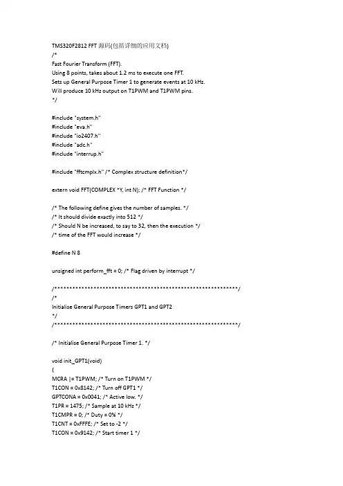
TMS320F2812 FFT源码(包括详细的应用文档)/*Fast Fourier Transform (FFT).Using 8 points, takes about 1.2 ms to execute one FFT.Sets up General Purpose Timer 1 to generate events at 10 kHz.Will produce 10 kHz output on T1PWM and T1PWM pins.*/#include "system.h"#include "eva.h"#include "io2407.h"#include "adc.h"#include "interrup.h"#include "fftcmplx.h" /* Complex structure definition*/extern void FFT(COMPLEX *Y, int N); /* FFT Function *//* The following define gives the number of samples. *//* It should divide exactly into 512 *//* Should N be increased, to say to 32, then the execution *//* time of the FFT would increase */#define N 8unsigned int perform_fft = 0; /* Flag driven by interrupt *//*************************************************************/ /*Initialise General Purpose Timers GPT1 and GPT2*//*************************************************************/ /* Initialise General Purpose Timer 1. */void init_GPT1(void){MCRA |= T1PWM; /* Turn on T1PWM */T1CON = 0x8142; /* Turn off GPT1 */GPTCONA = 0x0041; /* Active low. */T1PR = 1475; /* Sample at 10 kHz */T1CMPR = 0; /* Duty = 0% */T1CNT = 0xFFFE; /* Set to -2 */T1CON = 0x9142; /* Start timer 1 */EVAIFRA = 0xFFFF; /* Clear any pending interrupts */EVAIMRA |= T1PINT_FLAG; /* Enable T1 period interrupt */}/* Initialise General Purpose Timer 2 */void init_GPT2(void){MCRA |= T2PWM; /* Turn on T2PWM */T2CON = 0x8142; /* Turn off GPT2 */GPTCONA |= 0x0008; /* Controlled from GPT1 */T2PR = 1475; /* Sample at 10 kHz */T2CMPR = 0; /* Duty cycle 0% decimal */T2CNT = 0xFFFE; /* Set to -2 */T2CON = 0x9142; /* Start timer 2 */}/**************************************************************/void init_ADC(){/* Non Cascade for 8 measurements. *//* Will affect RESULT0 to RESULT7 only */ADCCTRL1 = (ADC_SOFT | ADC_CPS /*| ADC_ACQ_PS3 | ADC_ACQ_PS2*/ );CHSELSEQ1 = 0x3210; /* 8 measurements 0 */CHSELSEQ2 = 0x0000;CHSELSEQ3 = 0xFFFF;CHSELSEQ4 = 0xFFFF;MAX_CONV = 0x0007; /* 8 measurements, not 0 *//* Reset sequence at zero and software start of conversion */ADCCTRL2 = ( RST_SEQ1 | SOC_SEQ1);} /* No semicolon here *//***********************************************************/int input_buffer[N] = {8191, 8191, 8191, 8191, 0, 0, 0, 0};COMPLEX y[N]; /* Variable passed to FFT and modified *//***********************************************************/ /*Shuffle input buffer along one place.Put latest input from ADC into first buffer location.Input from ADCIN2 lies in range 0 to FFC0h (65472 decimal).Divide by 8 to limit range from 0 to 8184.*//***********************************************************/void shuffle_and_read(void){signed int i;for ( i = N-1 ; i > 0 ; i--){input_buffer = input_buffer[i-1];}input_buffer[0] = (RESULT2 >> 3);}/***********************************************************/ /*Copy from input buffer to complex structure.When FFT is performed, the complex structure is overwrittenby the return values.*//***********************************************************/void copy_input_to_complex(void){unsigned int i;for ( i = 0 ; i < N; i++){(y).real = input_buffer;(y).imag = 0;}}/***********************************************************/ /*Main programUses timers to read analog input on ADCIN2 into a bufferand then perform an 8-point FFT on it.*//**********************************************************/void main(void){signed int output1, output2;signed int x; /* General purpose variable. */signed int i; /* Counter */signed long temp;init_system(); /* Initialize variables and hardware */init_ADC(); /* Initialise ADC */init_GPT1(); /* Turn on timer 1 */init_GPT2(); /* Turn on timer 2 */MCRB &= 0xFFFE; /* I/O on IOPC0 for monitoring purposes */IMR |= INT2; /* Turn on INT 2 */asm(" CLRC INTM"); /* Turn on maskable interrupts */for ( ;; ){if ( perform_fft != 0 ){perform_fft = 0; /* Clear flag used to start fft */PCDATDIR = 0x0101; /* IOPC0 high */ADCCTRL2 |= SOC_SEQ1; /* Start next conversion*/copy_input_to_complex(); /* Copy inputs from receive buffer */FFT(y,8); /* Calls generic FFT function*//* Determine magnitude of (y[0]).real *//* output1 lies in range 0 to 32736 */if ( (y[0]).real > 0)output1 = (y[0]).real;elseoutput1 = -(y[0]).real;/* Determine magnitude of (y[0]).real *//* output2 lies in range -32736 to 32736 */if ( (y[2]).real > 0)output2 = (y[2]).real;elseoutput2 = -(y[2]).real;/* Scale output in range 0 to 1475 */temp = (signed long)(output1 * 2952);output1 = (signed int)(temp >> 16);T1CMPR = output1;temp = (signed long)( output2 * 2952);output2 = (signed int)(temp >> 16);T2CMPR = output1;shuffle_and_read(); /* Read in latest value from ADC *//* and put into buffer */PCDATDIR = 0x0100; /* IOPC0 low */} /* End if */} /* End for */} /* End main() *//************************************************************//* Interrupt routine *//* The interrupt occurs once every 0.1 ms./* Will make perform_fft = 1 once every 20 * 0.1 ms = 2 ms */void c_int2(void){static unsigned int x;if ( 0x0027 == PIVR){EVAIFRA |= T1PINT_FLAG; /* Clear GPT1 period interrupt */if ( x < 19 ) /* Increase if FFT with more points */{x++;}else{x = 0;perform_fft = 1; /* Global flag to start FFT */}}}/* End of fft.c */完整的快速傅立叶变换和逆变换(FFT IFFT)C语言算法函数语句:void kbfft(pr,pi,n,k,fr,fi,l,il)pr-----双精度实型一维数组,长度为n。
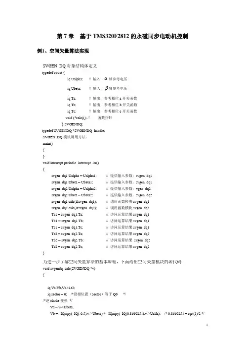
第7章基于TMS320F2812的永磁同步电动机控制例1、空间矢量算法实现SVGEN_DQ对象结构体定义typedef struct {_iq Ualpha; // 输入:α轴参考电压_iq Ubeta; // 输入:β轴参考电压_iq Ta; // 输出:参考相位a开关函数_iq Tb; // 输出:参考相位b开关函数_iq Tc; // 输出:参考相位c开关函数void (*calc)(); // 函数指针} SVGENDQ;typedef SVGENDQ *SVGENDQ_handle;SVGEN_DQ模块调用方法:main(){}void interrupt periodic_interrupt_isr(){svgen_dq1.Ualpha = Ualpha1; // 提供输入参数:svgen_dq1svgen_dq1.Ubeta = Ubeta1; // 提供输入参数:svgen_dq1svgen_dq2.Ualpha = Ualpha2; // 提供输入参数:vgen_dq2svgen_dq2.Ubeta = Ubeta2; // 提供输入参数:svgen_dq2svgen_dq1.calc(&svgen_dq1); // 调用函数模块svgen_dq1svgen_dq2.calc(&svgen_dq2); // 调用函数模块svgen_dq2Ta1 = svgen_dq1.Ta; // 访问运算结果svgen_dq1Tb1 = svgen_dq1.Tb; // 访问运算结果svgen_dq1Tc1 = svgen_dq1.Tc; // 访问运算结果svgen_dq1Ta2 = svgen_dq2.Ta; // 访问运算结果svgen_dq2Tb2 = svgen_dq2.Tb; // 访问运算结果svgen_dq2Tc2 = svgen_dq2.Tc; // 访问运算结果svgen_dq2}为进一步了解空间矢量算法的基本原理,下面给出空间矢量模块的源代码:void svgendq_calc(SVGENDQ *v){_iq Va,Vb,Vc,t1,t2;_iq sector = 0; /*设相位置(sector)等于Q0 *//*逆clarke变换*/Va = v->Ubeta;Vb = _IQmpy(_IQ(-0.5),v->Ubeta) + _IQmpy(_IQ(0.8660254),v->Ualfa); /* 0.8660254 = sqrt(3)/2 */Vc = _IQmpy(_IQ(-0.5),v->Ubeta) - _IQmpy(_IQ(0.8660254),v->Ualfa); /* 0.8660254 = sqrt(3)/2 *//* 60度sector的确定*/if (Va>_IQ(0))sector = 1;if (Vb>_IQ(0))sector = sector + 2;if (Vc>_IQ(0))sector = sector + 4;/* X,Y,Z (Va,Vb,Vc)的计算*/Va = v->Ubeta; /* X = Va */Vb = _IQmpy(_IQ(0.5),v->Ubeta) + _IQmpy(_IQ(0.8660254),v->Ualfa); /* Y = Vb */Vc = _IQmpy(_IQ(0.5),v->Ubeta) - _IQmpy(_IQ(0.8660254),v->Ualfa); /* Z = Vc */if (sector==1) /* sector 1: t1=Z and t2=Y (abc ---> Tb,Ta,Tc) */{t1 = Vc;t2 = Vb;v->Tb = _IQmpy(_IQ(0.5),(_IQ(1)-t1-t2)); /* tbon = (1-t1-t2)/2 */v->Ta = v->Tb+t1; /* taon = tbon+t1 */v->Tc = v->Ta+t2; /* tcon = taon+t2 */}else if (sector==2) /* sector 2: t1=Y and t2=-X (abc ---> Ta,Tc,Tb) */{t1 = Vb;t2 = -Va;v->Ta = _IQmpy(_IQ(0.5),(_IQ(1)-t1-t2)); /* taon = (1-t1-t2)/2 */v->Tc = v->Ta+t1; /* tcon = taon+t1 */v->Tb = v->Tc+t2; /* tbon = tcon+t2 */}else if (sector==3) /* sector 3: t1=-Z and t2=X (abc ---> Ta,Tb,Tc) */{t1 = -Vc;t2 = Va;v->Ta = _IQmpy(_IQ(0.5),(_IQ(1)-t1-t2)); /* taon = (1-t1-t2)/2 */v->Tb = v->Ta+t1; /* tbon = taon+t1 */v->Tc = v->Tb+t2; /* tcon = tbon+t2 */}else if (sector==4) /* sector 4: t1=-X and t2=Z (abc ---> Tc,Tb,Ta) */{t1 = -Va;t2 = Vc;v->Tc = _IQmpy(_IQ(0.5),(_IQ(1)-t1-t2)); /* tcon = (1-t1-t2)/2 */v->Tb = v->Tc+t1; /* tbon = tcon+t1 */v->Ta = v->Tb+t2; /* taon = tbon+t2 */}else if (sector==5) /* sector 5: t1=X and t2=-Y (abc ---> Tb,Tc,Ta) */{t1 = Va;t2 = -Vb;v->Tb = _IQmpy(_IQ(0.5),(_IQ(1)-t1-t2)); /* tbon = (1-t1-t2)/2 */v->Tc = v->Tb+t1; /* tcon = tbon+t1 */v->Ta = v->Tc+t2; /* taon = tcon+t2 */}else if (sector==6) /* sector 6: t1=-Y and t2=-Z (abc ---> Tc,Ta,Tb) */{t1 = -Vb;t2 = -Vc;v->Tc = _IQmpy(_IQ(0.5),(_IQ(1)-t1-t2)); /* tcon = (1-t1-t2)/2 */v->Ta = v->Tc+t1; /* taon = tcon+t1 */v->Tb = v->Ta+t2; /* tbon = taon+t2 */}v->Ta = _IQmpy(_IQ(2),(v->Ta-_IQ(0.5)));v->Tb = _IQmpy(_IQ(2),(v->Tb-_IQ(0.5)));v->Tc = _IQmpy(_IQ(2),(v->Tc-_IQ(0.5)));}在相位置(sector)3中的一个矢量的例子:PWM1PWM3PWM5图相位置(sector)PWM 实例及其占空比例2、事件管理器配置EvaRegs.T1PR = p->n_period; /* SYSTEM_FREQUENCY*1000000*T/2 *//*初始化Timer 1周期寄存器*//* 预定标器X1 (T1),ISR周期= T x 1 */ EvaRegs.T1CON.all = PWM_INIT_STATE; /* 对称操作模式*/ EvaRegs.DBTCONA.all = DBTCON_INIT_STATE;EvaRegs.ACTRA.all = ACTR_INIT_STATE;CONA.all = 0xA200;EvaRegs.CMPR1 = p->n_period;EvaRegs.CMPR2 = p->n_period;EvaRegs.CMPR3 = p->n_period;EALLOW;GpioMuxRegs.GPAMUX.all |= 0x003F;例3、TMS320F2812电流及DC母线电压检测//******************************************************************************// TMS320F2812电流及DC母线电压检测// 文件名称:F28XILEG_VDC.C//****************************************************************************** #include "DSP28_Device.h"#include "f28xileg_vdc.h"#include "f28xbmsk.h"#define CPU_CLOCK_SPEED 6.6667L // CPU时钟速度150MHz#define ADC_usDELAY 5000L#define DELAY_US(A) DSP28x_usDelay(((((long double) A * 1000.0L)/ (long double)CPU_CLOCK_SPEED) - 9.0L) / 5.0L) extern void DSP28x_usDelay(unsigned long Count);void F28X_ileg2_dcbus_drv_init(ILEG2DCBUSMEAS *p){DELAY_US(ADC_usDELAY);AdcRegs.ADCTRL1.all = ADC_RESET_FLAG; /*复位ADC模块*/asm(" NOP ");asm(" NOP ");AdcRegs.ADCTRL3.bit.ADCBGRFDN = 0x3; /* 为bandgap和参考电路供电*/DELAY_US(ADC_usDELAY); /*为ADC其他单元上电前延时*/AdcRegs.ADCTRL3.bit.ADCPWDN = 1; /*为ADC其他单元上电*/AdcRegs.ADCTRL3.bit.ADCCLKPS = 3; /* 设置ADCTRL3寄存器*/DELAY_US(ADC_usDELAY);AdcRegs.ADCTRL1.all = ADCTRL1_INIT_STATE; /*设置ADCTRL1寄存器*/AdcRegs.ADCTRL2.all = ADCTRL2_INIT_STATE; /*设置ADCTRL2寄存器*/AdcRegs.ADCMAXCONV.bit.MAX_CONV = 2; /* 确定3个转换*/AdcRegs.ADCCHSELSEQ1.all = p->Ch_sel; /* 配置通道选择*/EvaRegs.GPTCONA.bit.T1TOADC = 1; /*设置采用Timer1 UF触发ADC转换*/ }void F28X_ileg2_dcbus_drv_read(ILEG2DCBUSMEAS *p){int dat_q15;long tmp;/* 等待ADC转换结束*/while (AdcRegs.ADCST.bit.SEQ1_BSY == 1){};dat_q15 = AdcRegs.ADCRESULT0^0x8000; /*将转换结果变成Q15格式双极性数据*/tmp = (long)(p->Imeas_a_gain*dat_q15);p->Imeas_a = (int)(tmp>>13);p->Imeas_a += p->Imeas_a_offset;p->Imeas_a *= -1; /*正向,电流流向电动机*/dat_q15 = AdcRegs.ADCRESULT1^0x8000; /*将转换结果变成Q15格式双极性数据*/tmp = (long)(p->Imeas_b_gain*dat_q15);p->Imeas_b = (int)(tmp>>13);p->Imeas_b += p->Imeas_b_offset;p->Imeas_b *= -1; /*正向,电流流向电动机*/dat_q15 = (AdcRegs.ADCRESULT2>>1)&0x7FFF; /*将转换结果变成Q15格式双极性数据*/tmp = (long)(p->Vdc_meas_gain*dat_q15);p->Vdc_meas = (int)(tmp>>13);p->Vdc_meas += p->Vdc_meas_offset;p->Imeas_c = -(p->Imeas_a + p->Imeas_b);AdcRegs.ADCTRL2.all |= 0x4040; /* 复位排序器*/}例4、电动机位置检测/******************************************************************************// TMS320F2812电动机位置检测QEP电路初始化及应用// 文件名称:F28XQEP.C//******************************************************************************#include "DSP28_Device.h"#include "f28xqep.h"#include "f28xbmsk.h"void F28X_EV1_QEP_Init(QEP *p){EvaRegs.CAPCON.all = QEP_CAP_INIT_STATE; /*设置捕捉单元*/EvaRegs.T2CON.all = QEP_TIMER_INIT_STATE; /*设置捕捉定时器*/EvaRegs.T2PR = 0xFFFF;EvaRegs.EV AIFRC.bit.CAP3INT = 1; /*清除CAP3标志*/EvaRegs.EV AIMRC.bit.CAP3INT = 1; /*使能CAP3中断*/GpioMuxRegs.GPAMUX.all |= 0x0700; /*配置捕捉单元的引脚*/}void F28X_EV1_QEP_Calc(QEP *p){long tmp;p->dir_QEP = 0x4000&EvaRegs.GPTCONA.all;p->dir_QEP = p->dir_QEP>>14;p->theta_raw = EvaRegs.T2CNT + p->cal_angle;tmp = (long)(p->theta_raw*p->mech_scaler); /* Q0*Q26 = Q26 */tmp &= 0x03FFF000;p->theta_mech = (int)(tmp>>11); /* Q26 -> Q15 */p->theta_mech &= 0x7FFF;p->theta_elec = p->pole_pairs*p->theta_mech; /* Q0*Q15 = Q15 */p->theta_elec &= 0x7FFF;}void F28X_EV1_QEP_Isr(QEP *p){p->QEP_cnt_idx = EvaRegs.T2CNT;EvaRegs.T2CNT = 0;p->index_sync_flag = 0x00F0;}//****************************************************************************** // TMS320F2812电动机位置检测QEP电路初始化参数及函数定义// 文件名称:F28XQEP.H//******************************************************************************#ifndef __F28X_QEP_H__#define __F28X_QEP_H__#include "f28xbmsk.h"/* 初始化T2CON和CAPCON */#define QEP_CAP_INIT_STATE 0x9004#define QEP_TIMER_INIT_STATE (FREE_RUN_FLAG + \TIMER_DIR_UPDN + \TIMER_CLK_PRESCALE_X_1 + \TIMER_ENABLE_BY_OWN + \TIMER_ENABLE + \TIMER_CLOCK_SRC_QEP + \TIMER_COMPARE_LD_ON_ZERO)/* 定义QEP (正交编码电路) 驱动的对象*/typedef struct {int theta_elec; /* 输出: 电动机电角度(Q15) */ int theta_mech; /* 输出: 电动机机械角度(Q15) */int dir_QEP; /* 输出: 电动机转动方向(Q0) */int QEP_cnt_idx; /* 变量: 编码器计数(Q0) */int theta_raw; /* 变量: 定时器2得出的角度(Q0) */int mech_scaler; /* 参数: 0.9999/计数最大值,计数最大值= 4000 (Q26) */int pole_pairs; /* 参数: 极对数(Q0) */int cal_angle; /* 参数: 编码器和相之间的角度偏移量(Q0) */int index_sync_flag; /* 输出: Index sync status (Q0) */void (*init)(); /* 初始化函数指针*/void (*calc)(); /* 计算函数指针*/void (*isr)(); /* 中断程序指针*/} QEP;/* 定义一个QEP_handle */typedef QEP *QEP_handle;#define QEP_DEFAULTS { 0x0, 0x0,0x0,0x0,0x0,16776,2,-2365,0x0, \(void (*)(long))F28X_EV1_QEP_Init, \(void (*)(long))F28X_EV1_QEP_Calc, \(void (*)(long))F28X_EV1_QEP_Isr }void F28X_EV1_QEP_Init(QEP_handle);void F28X_EV1_QEP_Calc(QEP_handle);void F28X_EV1_QEP_Isr(QEP_handle);#endif /* __F28X_QEP_H__ */例5、TMS320F2812实现三相永磁同步电动机的磁场定向控制//****************************************************************************** // 采用TMS320F2812实现三相永磁同步电动机的磁场定向控制// 文件名称:PMSM3_1.C//****************************************************************************** //初始化程序#include "IQmathLib.h" /* 包含IQmath库函数的头文件*/#include "DSP28_Device.h"#include "pmsm3_1.h"#include "parameter.h"#include "build.h"// 函数声明interrupt void EvaTimer1(void);interrupt void EvaTimer2(void);// 全局变量定义float Vd_testing = 0; /* Vd testing (pu) */float Vq_testing = 0.25; /* Vq testing (pu) */float Id_ref = 0; /* Id reference (pu) */float Iq_ref = 0.4; /* Iq reference (pu) */float speed_ref = 0.2; /* Speed reference (pu) */float T = 0.001/ISR_FREQUENCY; /* Samping period (sec), see parameter.h */int isr_ticker = 0;int pwmdac_ch1=0;int pwmdac_ch2=0;int pwmdac_ch3=0;volatile int enable_flg=0;int lockrtr_flg=1;int speed_loop_ps = 10; // 速度环定标器int speed_loop_count = 1; // 速度环计数器CLARKE clarke1 = CLARKE_DEFAULTS;PARK park1 = PARK_DEFAULTS;IPARK ipark1 = IPARK_DEFAULTS;PIDREG3 pid1_id = PIDREG3_DEFAULTS;PIDREG3 pid1_iq = PIDREG3_DEFAULTS;PIDREG3 pid1_spd = PIDREG3_DEFAULTS;PWMGEN pwm1 = PWMGEN_DEFAULTS;PWMDAC pwmdac1 = PWMDAC_DEFAULTS;SVGENDQ svgen_dq1 = SVGENDQ_DEFAULTS;QEP qep1 = QEP_DEFAULTS;SPEED_MEAS_QEP speed1 = SPEED_MEAS_QEP_DEFAULTS; DRIVE drv1 = DRIVE_DEFAULTS;RMPCNTL rc1 = RMPCNTL_DEFAULTS;RAMPGEN rg1 = RAMPGEN_DEFAULTS;ILEG2DCBUSMEAS ilg2_vdc1 = ILEG2DCBUSMEAS_DEFAULTS;// 主函数void main(void){// 系统初始化InitSysCtrl();// HISPCP 设置EALLOW;SysCtrlRegs.HISPCP.all = 0x0000; /* SYSCLKOUT/1 */ EDIS;// 禁止并清除所有CPU中断:DINT;IER = 0x0000;IFR = 0x0000;// 初始化Pie到默认状态InitPieCtrl();// 初始化PIE相量表InitPieVectTable();// 初始化EV A 定时器1://设置定时器1寄存器(EV A)EvaRegs.GPTCONA.all = 0;//等待使能标志位while (enable_flg==0){// 使能定时器1的下溢中断EvaRegs.EV AIMRA.bit.T1UFINT = 1;EvaRegs.EV AIFRA.bit.T1UFINT = 1;// 使能CAP3中断(定时器2)EvaRegs.EV AIMRC.bit.CAP3INT = 1;EvaRegs.EV AIMRC.bit.CAP3INT = 1;};// 重新分配中断向量EALLOW;PieVectTable.T1UFINT = &EvaTimer1;PieVectTable.CAPINT3 = &EvaTimer2;EDIS;// 使能PIE组2的中断6(T1UFINT)PieCtrlRegs.PIEIER2.all = M_INT6;// 使能PIE组3的中断7(CAPINT3)PieCtrlRegs.PIEIER3.all = M_INT7;// 使能CPU INT2(T1UFINT)和INT3(CAPINT3):IER |= (M_INT2 | M_INT3);// 使能全局中断和最高优先级适时调试事件管理器功能:EINT; //使能全局中断INTMERTM; // 使能适时调试中断DBGM/* 模块初始化*/pwm1.n_period = SYSTEM_FREQUENCY*1000000*T/2; /* 预定标器X1 (T1), ISR周期= T x 1 */ pwm1.init(&pwm1);pwmdac1.pwmdac_period = 2500; /* PWM频率= 30 kHz */pwmdac1.PWM_DAC_IPTR0 = &pwmdac_ch1;pwmdac1.PWM_DAC_IPTR1 = &pwmdac_ch2;pwmdac1.PWM_DAC_IPTR2 = &pwmdac_ch3;pwmdac1.init(&pwmdac1);qep1.init(&qep1);drv1.init(&drv1);ilg2_vdc1.init(&ilg2_vdc1);/* 初始化SPEED_FRQ模块*/speed1.K1 = _IQ21(1/(BASE_FREQ*T));speed1.K2 = _IQ(1/(1+T*2*PI*30)); /* 低通截至频率= 30 Hz */speed1.K3 = _IQ(1)-speed1.K2;speed1.rpm_max = 120*BASE_FREQ/P;/*初始化RAMPGEN模块*/rg1.step_angle_max = _IQ(BASE_FREQ*T);/* 初始化PID_REG3 Id调节模块*/pid1_id.Kp_reg3 = _IQ(0.75);pid1_id.Ki_reg3 = _IQ(T/0.0005);pid1_id.Kd_reg3 = _IQ(0/T);pid1_id.Kc_reg3 = _IQ(0.2);pid1_id.pid_out_max = _IQ(0.30);pid1_id.pid_out_min = _IQ(-0.30);/* 初始化PID_REG3 Iq调节模块*/pid1_iq.Kp_reg3 = _IQ(0.75);pid1_iq.Ki_reg3 = _IQ(T/0.0005);pid1_iq.Kd_reg3 = _IQ(0/T);pid1_iq.Kc_reg3 = _IQ(0.2);pid1_iq.pid_out_max = _IQ(0.95);pid1_iq.pid_out_min = _IQ(-0.95);/*初始化PID_REG3 速度调节模块*/pid1_spd.Kp_reg3 = _IQ(1);pid1_spd.Ki_reg3 = _IQ(T*speed_loop_ps/0.1);pid1_spd.Kd_reg3 = _IQ(0/(T*speed_loop_ps));pid1_spd.Kc_reg3 = _IQ(0.2);pid1_spd.pid_out_max = _IQ(1);pid1_spd.pid_out_min = _IQ(-1);// 循环等待for(;;);}interrupt void EvaTimer1(void){isr_ticker++;if (speed_loop_count==speed_loop_ps){11pid1_spd.pid_ref_reg3 = _IQ(speed_ref);pid1_spd.pid_fdb_reg3 = speed1.speed_frq;pid1_spd.calc(&pid1_spd);speed_loop_count=1;}else speed_loop_count++;pid1_iq.pid_ref_reg3 = pid1_spd.pid_out_reg3;pid1_iq.pid_fdb_reg3 = park1.qe;pid1_iq.calc(&pid1_iq);pid1_id.pid_ref_reg3 = _IQ(Id_ref);pid1_id.pid_fdb_reg3 = park1.de;pid1_id.calc(&pid1_id);ipark1.de = pid1_id.pid_out_reg3;ipark1.qe = pid1_iq.pid_out_reg3;ipark1.ang = speed1.theta_elec;ipark1.calc(&ipark1);svgen_dq1.Ualfa = ipark1.ds;svgen_dq1.Ubeta = ipark1.qs;svgen_dq1.calc(&svgen_dq1);pwm1.Mfunc_c1 = (int)_IQtoIQ15(svgen_dq1.Ta); /* Mfunc_c1 is in Q15 */pwm1.Mfunc_c2 = (int)_IQtoIQ15(svgen_dq1.Tb); /* Mfunc_c2 is in Q15 */pwm1.Mfunc_c3 = (int)_IQtoIQ15(svgen_dq1.Tc); /* Mfunc_c3 is in Q15 */pwm1.update(&pwm1);ilg2_vdc1.read(&ilg2_vdc1);clarke1.as = _IQ15toIQ((long)ilg2_vdc1.Imeas_a);clarke1.bs = _IQ15toIQ((long)ilg2_vdc1.Imeas_b);clarke1.calc(&clarke1);park1.ds = clarke1.ds;park1.qs = clarke1.qs;park1.ang = speed1.theta_elec;park1.calc(&park1);qep1.calc(&qep1);speed1.theta_elec = _IQ15toIQ((long)qep1.theta_elec);speed1.dir_QEP = (long)(qep1.dir_QEP);12speed1.calc(&speed1);pwmdac_ch1 = (int)_IQtoIQ15(svgen_dq1.Ta);pwmdac_ch2 = (int)_IQtoIQ15(clarke1.as);pwmdac_ch3 = (int)_IQtoIQ15(speed1.theta_elec);drv1.enable_flg = enable_flg;drv1.update(&drv1);pwmdac1.update(&pwmdac1);// 使能定时器中断EvaRegs.EV AIMRA.bit.T1UFINT = 1;EvaRegs.EV AIFRA.all = BIT9;PieCtrlRegs.PIEACK.all |= PIEACK_GROUP2;}interrupt void EvaTimer2(void){qep1.isr(&qep1);EvaRegs.EV AIMRC.bit.CAP3INT = 1;EvaRegs.EV AIFRC.all = BIT2;PieCtrlRegs.PIEACK.all |= PIEACK_GROUP3;}具体参考《零基础学TMS320F281xDSP C语言开发》,与书上重合率很高。
基于TMS320F2812处理器矢量控制永磁同步交流电机张涛
【期刊名称】《电脑开发与应用》
【年(卷),期】2010(23)12
【摘要】永磁同步交流电机(PMSAM)在电力传动领域发挥着重要的作用,是工业自动化不可缺少的组成部分,永磁同步电动机以其独特的优点适用于中小功率伺服场合.分析了永磁同步交流电机的数学模型和控制要求,介绍了永磁同步交流电机的矢量控制理论,并根据矢量控制理论运用TMS320F2812处理器对永磁同步交流伺服电机的控制.
【总页数】4页(P36-38,41)
【作者】张涛
【作者单位】国营785厂设计一所,太原,030024
【正文语种】中文
【中图分类】TM341
【相关文献】
1.基于TMS320F2812的双轴交流永磁同步电机伺服系统设计 [J], 雷力;李院生;易亚军;
2.基于TMS320F2812的交流永磁同步电机数字控制系统 [J], 黄笋翠;游林儒;王孝洪
3.交流矢量处理器AD2S100在永磁同步电机矢量控制中的应用 [J], 王明亮;唐永哲;庞振岳
4.基于TMS320F2812的永磁同步电机矢量控制研究 [J], 王雪丹;孙少杰
5.基于TMS320F28335的永磁同步交流伺服电机矢量控制系统设计 [J], 丁丽娜;崔新忠;何南
因版权原因,仅展示原文概要,查看原文内容请购买。
基于TMS320F2812 DSP的交流永磁同步直线电机控制2010年07月03日 08:51 电子产品世界作者:佚名用户评论(0)关键字:TMS320F281(20)制造业中需要的线形驱动力,传统的方法是用旋转电机加滚珠丝杠的方式提供。
实践证明,在许多高精密、高速度场合,这种驱动已经显露出不足。
在这种情况下直线电机应运而生。
直线电机直接产生直线运动,没有中间转换环节,动力是在气隙磁场中直接产生的,可获得比传统驱动机构高几倍的定位精度和快速响应速度。
本文是在我系研制的交流永磁同步直线电机基础上进行基于矢量变换控制的驱动系统设计应用。
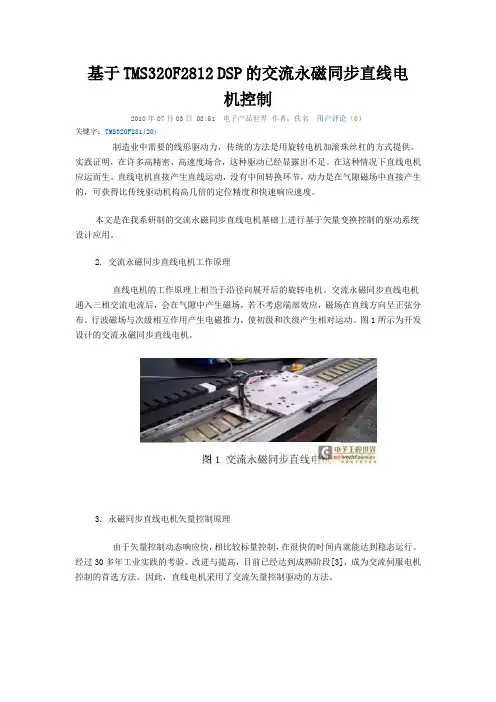
2. 交流永磁同步直线电机工作原理直线电机的工作原理上相当于沿径向展开后的旋转电机。
交流永磁同步直线电机通入三相交流电流后,会在气隙中产生磁场,若不考虑端部效应,磁场在直线方向呈正弦分布。
行波磁场与次级相互作用产生电磁推力,使初级和次级产生相对运动。
图1所示为开发设计的交流永磁同步直线电机。
3. 永磁同步直线电机矢量控制原理由于矢量控制动态响应快,相比较标量控制,在很快的时间内就能达到稳态运行。
经过30多年工业实践的考验、改进与提高,目前已经达到成熟阶段[3],成为交流伺服电机控制的首选方法。
因此,直线电机采用了交流矢量控制驱动的方法。
直线电机初级的三相电压(U、V、W相)构成了三相初级坐标系(a,b,c轴系),其中的三相绕组相角相差120?,即在水平方向上互差1/3极距。
参照旋转电机矢量变换理论,设定两相初级坐标系(α-β轴系),由三相初级坐标系到直角坐标系转换称为Clark 变换,见式(1)。
从静止坐标系到旋转坐标系的变换称为Park变换,见式(2)。
反之称Park逆变换。
θ是d轴与轴的夹角。
根据旋转电机的Park变换理论和两电机结构比较。
由于电机运动部分的不同,故直线电机动子相当于旋转电机定子,直线电机定子相当于旋转电机动子。
所以在旋转电机中旋转坐标系固定在动子上,旋转坐标系随着电机转子一起同步旋转。
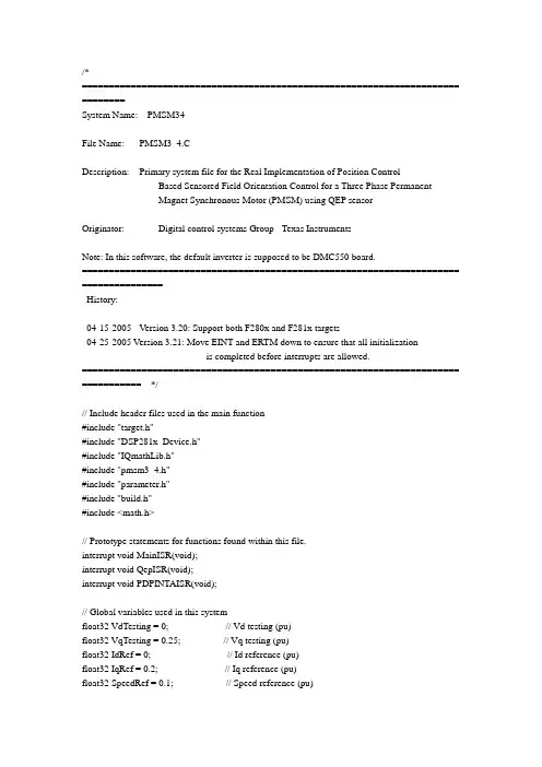
/*====================================================================== ========System Name: PMSM34File Name: PMSM3_4.CDescription: Primary system file for the Real Implementation of Position ControlBased Sensored Field Orientation Control for a Three Phase Permanent-Magnet Synchronous Motor (PMSM) using QEP sensorOriginator: Digital control systems Group - Texas InstrumentsNote: In this software, the default inverter is supposed to be DMC550 board.====================================================================== ===============History:-------------------------------------------------------------------------------------04-15-2005 Version 3.20: Support both F280x and F281x targets04-25-2005 Version 3.21: Move EINT and ERTM down to ensure that all initializationis completed before interrupts are allowed.====================================================================== =========== */// Include header files used in the main function#include "target.h"#include "DSP281x_Device.h"#include "IQmathLib.h"#include "pmsm3_4.h"#include "parameter.h"#include "build.h"#include <math.h>// Prototype statements for functions found within this file.interrupt void MainISR(void);interrupt void QepISR(void);interrupt void PDPINTAISR(void);// Global variables used in this systemfloat32 VdTesting = 0; // Vd testing (pu)float32 VqTesting = 0.25; // Vq testing (pu)float32 IdRef = 0; // Id reference (pu)float32 IqRef = 0.2; // Iq reference (pu)float32 SpeedRef = 0.1; // Speed reference (pu)float32 PositionRef = 0.5; // Position reference (Mechanical rotor Anglele (pu) float32 T = 0.001/ISR_FREQUENCY; // Samping period (sec), see parameter.hUint16 IsrTicker = 0;Uint16 BackTicker = 0;volatile Uint16 EnableFlag = FALSE;Uint16 LockRotorFlag = FALSE;Uint16 SpeedLoopPrescaler = 10; // Speed loop prescalerUint16 SpeedLoopCount = 1; // Speed loop counter// Instance a few transform objectsCLARKE clarke1 = CLARKE_DEFAULTS;PARK park1 = PARK_DEFAULTS;IPARK ipark1 = IPARK_DEFAULTS;// Instance PID regulators to regulate the d and q synchronous axis currents,// speed and positionPIDREG3 pid1_id = PIDREG3_DEFAULTS;PIDREG3 pid1_iq = PIDREG3_DEFAULTS;PIDREG3 pid1_pos = PIDREG3_DEFAULTS;PIDREG3 pid1_spd = PIDREG3_DEFAULTS;// Instance a PWM driver instancePWMGEN pwm1 = PWMGEN_DEFAULTS;// Instance a Space Vector PWM modulator. This modulator generates a, b and c// phases based on the d and q stationery reference frame inputsSVGENDQ svgen_dq1 = SVGENDQ_DEFAULTS;// Instance a QEP interface driverQEP qep1 = QEP_DEFAULTS;// Instance a speed calculator based on QEPSPEED_MEAS_QEP speed1 = SPEED_MEAS_QEP_DEFAULTS;// Instance a ramp controller to smoothly ramp the frequencyRMPCNTL rc1 = RMPCNTL_DEFAULTS;// Instance a ramp generator to simulate an AngleleRAMPGEN rg1 = RAMPGEN_DEFAULTS;// Create an instance of the current/dc-bus voltage measurement driverILEG2DCBUSMEAS ilg2_vdc1 = ILEG2DCBUSMEAS_DEFAULTS;void main(void){// ******************************************// Initialization code for DSP_TARGET = F2812// ******************************************// Initialize System Control registers, PLL, WatchDog, Clocks to default state: // This function is found in the DSP281x_SysCtrl.c file.InitSysCtrl();// HISPCP prescale register settings, normally it will be set to default values EALLOW; // This is needed to write to EALLOW protected registers SysCtrlRegs.HISPCP.all = 0x0000; // SYSCLKOUT/1EDIS; // This is needed to disable write to EALLOW protected registers// Disable and clear all CPU interrupts:DINT;IER = 0x0000;IFR = 0x0000;// Initialize Pie Control Registers To Default State:// This function is found in the DSP281x_PieCtrl.c file.InitPieCtrl();// Initialize the PIE Vector Table To a Known State:// This function is found in DSP281x_PieVect.c.// This function populates the PIE vector table with pointers// to the shell ISR functions found in DSP281x_DefaultIsr.c.InitPieVectTable();//Initialize GPIO;MUX为0,表示IO;MUX为1表示外围;//DIR为0,表示输入;DIR为1表示输出EALLOW;GpioMuxRegs.GPAMUX.all=0X073F;GpioMuxRegs.GPADIR.all=0XC0C0;GpioMuxRegs.GPBMUX.all=0X0000;GpioMuxRegs.GPBDIR.all=0X0000;GpioMuxRegs.GPDMUX.bit.T1CTRIP_PDPA_GPIOD0=1; //功能PDPINTA GpioMuxRegs.GPDMUX.bit.T2CTRIP_SOCA_GPIOD1=0; // INPUTGpioMuxRegs.GPDDIR.bit.GPIOD1=0;GpioMuxRegs.GPDMUX.bit.T3CTRIP_PDPB_GPIOD5=0;GpioMuxRegs.GPDDIR.bit.GPIOD5=0;GpioMuxRegs.GPDMUX.bit.T4CTRIP_SOCB_GPIOD6=0;GpioMuxRegs.GPDDIR.bit.GPIOD6=0;GpioMuxRegs.GPEMUX.bit.XINT1_XBIO_GPIOE0=0;GpioMuxRegs.GPEMUX.bit.XINT2_ADCSOC_GPIOE1=0;GpioMuxRegs.GPEMUX.bit.XNMI_XINT13_GPIOE2=0;GpioMuxRegs.GPEDIR.bit.GPIOE0=0;GpioMuxRegs.GPEDIR.bit.GPIOE1=0;GpioMuxRegs.GPEDIR.bit.GPIOE2=0;GpioMuxRegs.GPFMUX.all=0X4037;GpioMuxRegs.GPFDIR.all=0X01C8;GpioMuxRegs.GPGMUX.bit.SCITXDB_GPIOG4=0;GpioMuxRegs.GPGMUX.bit.SCIRXDB_GPIOG5=0;GpioMuxRegs.GPGDIR.bit.GPIOG4=1;GpioMuxRegs.GPGDIR.bit.GPIOG5=1;EDIS;// User specific functions, Reassign vectors (optional), Enable Interrupts:// Initialize EV A Timer 1:// Setup Timer 1 Registers (EV A)EvaRegs.GPTCONA.all = 0;// Waiting for enable flag setwhile (EnableFlag==FALSE){BackTicker++;}// Enable Underflow interrupt bits for GP timer 1EvaRegs.EVAIMRA.bit.T1UFINT = 1;EvaRegs.EVAIFRA.bit.T1UFINT = 1;// Enable CAP3 interrupt bits for GP timer 2EvaRegs.EVAIMRC.bit.CAP3INT = 1;EvaRegs.EVAIFRC.bit.CAP3INT = 1;// Reassign ISRs.// Reassign the PIE vector for T1UFINT and CAP3INT to point to a different// ISR then the shell routine found in DSP281x_DefaultIsr.c.// This is done if the user does not want to use the shell ISR routine// but instead wants to use their own ISR.EALLOW; // This is needed to write to EALLOW protected registersPieVectTable.T1UFINT = &MainISR;PieVectTable.CAPINT3 = &QepISR;PieVectTable.PDPINTA = &PDPINTAISR;EDIS; // This is needed to disable write to EALLOW protected registers// Enable PIE group 2 interrupt 6 for T1UFINTPieCtrlRegs.PIEIER2.all = M_INT6;// Enable PIE group 3 interrupt 7 for CAP3INTPieCtrlRegs.PIEIER3.all = M_INT7;// Enable PIE group 1 interrupt 1 for PDPINTAPieCtrlRegs.PIEIER1.all = M_INT1;// Enable CPU INT2 for T1UFINT and INT3 for CAP3INT:IER |= (M_INT2 | M_INT3 | M_INT1);// Initialize PWM modulepwm1.PeriodMax = SYSTEM_FREQUENCY*1000000*T/2; // Perscaler X1 (T1), ISR period = T x 1pwm1.init(&pwm1);// Initialize QEP moduleqep1.LineEncoder = 2000;qep1.MechScaler = _IQ30(0.25/qep1.LineEncoder);qep1.PolePairs = P/2;qep1.CalibratedAngle = -1250;qep1.init(&qep1);// Initialize the Speed module for QEP based speed calculationspeed1.K1 = _IQ21(1/(BASE_FREQ*T));speed1.K2 = _IQ(1/(1+T*2*PI*30)); // Low-pass cut-off frequencyspeed1.K3 = _IQ(1)-speed1.K2;speed1.BaseRpm = 120*(BASE_FREQ/P);// Initialize ADC module// Note for DMC550:// - At 24 dc-bus volt, the ADC input for measured Vdc_bus range is 24*1/(24.9+1) = 0.927 volt // - Then, Vdc_bus gain = 3.0/0.927 = 3.2375 (or 0x675C in Q13)ilg2_vdc1.VdcMeasGain = 0x675C;ilg2_vdc1.ChSelect = 0x0610;ilg2_vdc1.init(&ilg2_vdc1);// Initialize the RAMPGEN modulerg1.StepAngleMax = _IQ(BASE_FREQ*T);// Initialize the RAMPGEN modulerc1.RampDelayMax = 5;// Initialize the PID_REG3 module for Idpid1_id.Kp = _IQ(0.1);pid1_id.Ki = _IQ(T/0.02);pid1_id.Kd = _IQ(0/T);pid1_id.Kc = _IQ(0.5);pid1_id.OutMax = _IQ(0.30);pid1_id.OutMin = _IQ(-0.30);// Initialize the PID_REG3 module for Iqpid1_iq.Kp = _IQ(0.1);pid1_iq.Ki = _IQ(T/0.02);pid1_iq.Kd = _IQ(0/T);pid1_iq.Kc = _IQ(0.5);pid1_iq.OutMax = _IQ(0.95);pid1_iq.OutMin = _IQ(-0.95);// Initialize the PID_REG3 module for speed controlpid1_spd.Kp = _IQ(1);pid1_spd.Ki = _IQ(T*SpeedLoopPrescaler/0.3);pid1_spd.Kd = _IQ(0/(T*SpeedLoopPrescaler));pid1_spd.Kc = _IQ(0.2);pid1_spd.OutMax = _IQ(1);pid1_spd.OutMin = _IQ(-1);// Initialize the PID_REG3 module for position controlpid1_pos.Kp = _IQ(28.2);pid1_pos.Ki = _IQ(0); // Integral term is not usedpid1_pos.Kd = _IQ(0); // Derivative term is not usedpid1_pos.Kc = _IQ(0);pid1_pos.OutMax = _IQ(1);pid1_pos.OutMin = _IQ(-1);// Enable global Interrupts and higher priority real-time debug events:EINT; // Enable Global interrupt INTMERTM; // Enable Global realtime interrupt DBGM// IDLE loop. Just sit and loop forever:for(;;) BackTicker++;}interrupt void MainISR(void){// Verifying the ISRIsrTicker++;// ***************** LEVEL1 *****************#if (BUILDLEVEL==LEVEL1)// ------------------------------------------------------------------------------// Connect inputs of the RMP module and call the Ramp control// calculation function.// ------------------------------------------------------------------------------rc1.TargetValue = _IQ(SpeedRef);rc1.calc(&rc1);// ------------------------------------------------------------------------------// Connect inputs of the RAMP GEN module and call the Ramp generator// calculation function.// ------------------------------------------------------------------------------rg1.Freq = rc1.SetpointValue;rg1.calc(&rg1);// ------------------------------------------------------------------------------// Connect inputs of the INV_PARK module and call the inverse park transformation // calculation function.// ------------------------------------------------------------------------------ipark1.Ds = _IQ(VdTesting);ipark1.Qs = _IQ(VqTesting);ipark1.Angle = rg1.Out;ipark1.calc(&ipark1);// ------------------------------------------------------------------------------// Connect inputs of the SVGEN_DQ module and call the space-vector gen.// calculation function.// ------------------------------------------------------------------------------svgen_dq1.Ualpha = ipark1.Alpha;svgen_dq1.Ubeta = ipark1.Beta;svgen_dq1.calc(&svgen_dq1);// ------------------------------------------------------------------------------// Connect inputs of the PWM_DRV module and call the PWM signal generation // update function.// ------------------------------------------------------------------------------pwm1.MfuncC1 = (int16)_IQtoIQ15(svgen_dq1.Ta); // MfuncC1 is in Q15pwm1.MfuncC2 = (int16)_IQtoIQ15(svgen_dq1.Tb); // MfuncC2 is in Q15pwm1.MfuncC3 = (int16)_IQtoIQ15(svgen_dq1.Tc); // MfuncC3 is in Q15pwm1.update(&pwm1);#endif // (BUILDLEVEL==LEVEL1)// ***************** LEVEL2 *****************#if (BUILDLEVEL==LEVEL2)// ------------------------------------------------------------------------------// Connect inputs of the RMP module and call the Ramp control// calculation function.// ------------------------------------------------------------------------------rc1.TargetValue = _IQ(SpeedRef);rc1.calc(&rc1);// ------------------------------------------------------------------------------// Connect inputs of the RAMP GEN module and call the Ramp generator// calculation function.// ------------------------------------------------------------------------------rg1.Freq = rc1.SetpointValue;rg1.calc(&rg1);// ------------------------------------------------------------------------------// Call the ILEG2_VDC read function.// ------------------------------------------------------------------------------ilg2_vdc1.read(&ilg2_vdc1);// ------------------------------------------------------------------------------// Connect inputs of the CLARKE module and call the clarke transformation// calculation function.// ------------------------------------------------------------------------------clarke1.As = _IQ15toIQ((int32)ilg2_vdc1.ImeasA);clarke1.Bs = _IQ15toIQ((int32)ilg2_vdc1.ImeasB);clarke1.calc(&clarke1);// ------------------------------------------------------------------------------// Connect inputs of the PARK module and call the park transformation// calculation function.// ------------------------------------------------------------------------------park1.Alpha = clarke1.Alpha;park1.Beta = clarke1.Beta;park1.Angle = rg1.Out;park1.calc(&park1);// ------------------------------------------------------------------------------// Connect inputs of the INV_PARK module and call the inverse park transformation // calculation function.// ------------------------------------------------------------------------------ipark1.Ds = _IQ(VdTesting);ipark1.Qs = _IQ(VqTesting);ipark1.Angle = rg1.Out;ipark1.calc(&ipark1);// ------------------------------------------------------------------------------// Connect inputs of the SVGEN_DQ module and call the space-vector gen.// calculation function.// ------------------------------------------------------------------------------svgen_dq1.Ualpha = ipark1.Alpha;svgen_dq1.Ubeta = ipark1.Beta;svgen_dq1.calc(&svgen_dq1);// ------------------------------------------------------------------------------// Connect inputs of the PWM_DRV module and call the PWM signal generation// update function.// ------------------------------------------------------------------------------pwm1.MfuncC1 = (int16)_IQtoIQ15(svgen_dq1.Ta); // MfuncC1 is in Q15pwm1.MfuncC2 = (int16)_IQtoIQ15(svgen_dq1.Tb); // MfuncC2 is in Q15pwm1.MfuncC3 = (int16)_IQtoIQ15(svgen_dq1.Tc); // MfuncC3 is in Q15pwm1.update(&pwm1);#endif // (BUILDLEVEL==LEVEL2)// ***************** LEVEL3 *****************#if (BUILDLEVEL==LEVEL3)// ------------------------------------------------------------------------------// Connect inputs of the RMP module and call the Ramp control// calculation function.// ------------------------------------------------------------------------------ rc1.TargetValue = _IQ(SpeedRef);rc1.calc(&rc1);// ------------------------------------------------------------------------------// Connect inputs of the RAMP GEN module and call the Ramp generator // calculation function.// ------------------------------------------------------------------------------ rg1.Freq = rc1.SetpointValue;rg1.calc(&rg1);// ------------------------------------------------------------------------------// Call the ILEG2_VDC read function.// ------------------------------------------------------------------------------ ilg2_vdc1.read(&ilg2_vdc1);// ------------------------------------------------------------------------------// Connect inputs of the CLARKE module and call the clarke transformation // calculation function.// ------------------------------------------------------------------------------ clarke1.As = _IQ15toIQ((int32)ilg2_vdc1.ImeasA);clarke1.Bs = _IQ15toIQ((int32)ilg2_vdc1.ImeasB);clarke1.calc(&clarke1);// ------------------------------------------------------------------------------// Connect inputs of the PARK module and call the park transformation// calculation function.// ------------------------------------------------------------------------------ park1.Alpha = clarke1.Alpha;park1.Beta = clarke1.Beta;park1.Angle = rg1.Out;park1.calc(&park1);// ------------------------------------------------------------------------------// Connect inputs of the PID_REG3 module and call the PID IQ controller // calculation function.// ------------------------------------------------------------------------------ pid1_iq.Ref = _IQ(IqRef);pid1_iq.Fdb = park1.Qs;pid1_iq.calc(&pid1_iq);// ------------------------------------------------------------------------------// Connect inputs of the PID_REG3 module and call the PID ID controller// calculation function.// ------------------------------------------------------------------------------pid1_id.Ref = _IQ(IdRef);pid1_id.Fdb = park1.Ds;pid1_id.calc(&pid1_id);// ------------------------------------------------------------------------------// Connect inputs of the INV_PARK module and call the inverse park transformation // calculation function.// ------------------------------------------------------------------------------ipark1.Ds = pid1_id.Out;ipark1.Qs = pid1_iq.Out;ipark1.Angle = rg1.Out;ipark1.calc(&ipark1);// ------------------------------------------------------------------------------// Connect inputs of the SVGEN_DQ module and call the space-vector gen.// calculation function.// ------------------------------------------------------------------------------svgen_dq1.Ualpha = ipark1.Alpha;svgen_dq1.Ubeta = ipark1.Beta;svgen_dq1.calc(&svgen_dq1);// ------------------------------------------------------------------------------// Connect inputs of the PWM_DRV module and call the PWM signal generation// update function.// ------------------------------------------------------------------------------pwm1.MfuncC1 = (int16)_IQtoIQ15(svgen_dq1.Ta); // MfuncC1 is in Q15pwm1.MfuncC2 = (int16)_IQtoIQ15(svgen_dq1.Tb); // MfuncC2 is in Q15pwm1.MfuncC3 = (int16)_IQtoIQ15(svgen_dq1.Tc); // MfuncC3 is in Q15pwm1.update(&pwm1);#endif // (BUILDLEVEL==LEVEL3)// ***************** LEVEL4 *****************#if (BUILDLEVEL==LEVEL4)// ------------------------------------------------------------------------------// Connect inputs of the RMP module and call the Ramp control// calculation function.// ------------------------------------------------------------------------------rc1.TargetValue = _IQ(SpeedRef);rc1.calc(&rc1);// ------------------------------------------------------------------------------// Connect inputs of the RAMP GEN module and call the Ramp generator// calculation function.// ------------------------------------------------------------------------------rg1.Freq = rc1.SetpointValue;rg1.calc(&rg1);// ------------------------------------------------------------------------------// Call the ILEG2_VDC read function.// ------------------------------------------------------------------------------ilg2_vdc1.read(&ilg2_vdc1);// ------------------------------------------------------------------------------// Connect inputs of the CLARKE module and call the clarke transformation// calculation function.// ------------------------------------------------------------------------------clarke1.As = _IQ15toIQ((int32)ilg2_vdc1.ImeasA);clarke1.Bs = _IQ15toIQ((int32)ilg2_vdc1.ImeasB);clarke1.calc(&clarke1);//-------------------------------------------------------------------------------------// Checking LockRotorFlag=FALSE for spinning mode, LockRotorFlag=TRUE for locked rotor mode//-------------------------------------------------------------------------------------if(LockRotorFlag==TRUE) // locked rotor mode if LockRotorFlag = 1{// ------------------------------------------------------------------------------// Connect inputs of the PARK module and call the park transformation// calculation function.// ------------------------------------------------------------------------------park1.Alpha = clarke1.Alpha;park1.Beta = clarke1.Beta;park1.Angle = 0;park1.calc(&park1);// ------------------------------------------------------------------------------// Connect inputs of the PID_REG3 module and call the PID IQ controller// calculation function.// ------------------------------------------------------------------------------pid1_iq.Ref = _IQ(IqRef);pid1_iq.Fdb = park1.Qs;pid1_iq.calc(&pid1_iq);// ------------------------------------------------------------------------------// Connect inputs of the PID_REG3 module and call the PID ID controller// calculation function.// ------------------------------------------------------------------------------pid1_id.Ref = _IQ(IdRef);pid1_id.Fdb = park1.Ds;pid1_id.calc(&pid1_id);// ------------------------------------------------------------------------------// Connect inputs of the INV_PARK module and call the inverse park transformation // calculation function.// ------------------------------------------------------------------------------ipark1.Ds = pid1_id.Out;ipark1.Qs = pid1_iq.Out;ipark1.Angle = 0;ipark1.calc(&ipark1);} // End: LockRotorFlag==TRUEelse if(LockRotorFlag==FALSE) // spinning mode if LockRotorFlag = 0{// ------------------------------------------------------------------------------// Connect inputs of the PARK module and call the park transformation// calculation function.// ------------------------------------------------------------------------------park1.Alpha = clarke1.Alpha;park1.Beta = clarke1.Beta;park1.Angle = rg1.Out;park1.calc(&park1);// ------------------------------------------------------------------------------// Connect inputs of the PID_REG3 module and call the PID IQ controller// calculation function.// ------------------------------------------------------------------------------pid1_iq.Ref = _IQ(IqRef);pid1_iq.Fdb = park1.Qs;pid1_iq.calc(&pid1_iq);// ------------------------------------------------------------------------------// Connect inputs of the PID_REG3 module and call the PID ID controller// calculation function.// ------------------------------------------------------------------------------pid1_id.Ref = _IQ(IdRef);pid1_id.Fdb = park1.Ds;pid1_id.calc(&pid1_id);// ------------------------------------------------------------------------------// Connect inputs of the INV_PARK module and call the inverse park transformation // calculation function.// ------------------------------------------------------------------------------ipark1.Ds = pid1_id.Out;ipark1.Qs = pid1_iq.Out;ipark1.Angle = rg1.Out;ipark1.calc(&ipark1);} // End: LockRotorFlag==FALSE// ------------------------------------------------------------------------------// Connect inputs of the SVGEN_DQ module and call the space-vector gen.// calculation function.// ------------------------------------------------------------------------------svgen_dq1.Ualpha = ipark1.Alpha;svgen_dq1.Ubeta = ipark1.Beta;svgen_dq1.calc(&svgen_dq1);// ------------------------------------------------------------------------------// Connect inputs of the PWM_DRV module and call the PWM signal generation// update function.// ------------------------------------------------------------------------------pwm1.MfuncC1 = (int16)_IQtoIQ15(svgen_dq1.Ta); // MfuncC1 is in Q15pwm1.MfuncC2 = (int16)_IQtoIQ15(svgen_dq1.Tb); // MfuncC2 is in Q15pwm1.MfuncC3 = (int16)_IQtoIQ15(svgen_dq1.Tc); // MfuncC3 is in Q15pwm1.update(&pwm1);// ------------------------------------------------------------------------------// Call the QEP_DRV calculation function.// ------------------------------------------------------------------------------qep1.calc(&qep1);// ------------------------------------------------------------------------------// Connect inputs of the SPEED_FR module and call the speed calculation function // ------------------------------------------------------------------------------speed1.ElecTheta = _IQ15toIQ((int32)qep1.ElecTheta);speed1.DirectionQep = (int32)(qep1.DirectionQep);speed1.calc(&speed1);#endif // (BUILDLEVEL==LEVEL4)// ***************** LEVEL5 *****************#if (BUILDLEVEL==LEVEL5)// ------------------------------------------------------------------------------// Call the ILEG2_VDC read function.// ------------------------------------------------------------------------------ilg2_vdc1.read(&ilg2_vdc1);// ------------------------------------------------------------------------------// Connect inputs of the CLARKE module and call the clarke transformation// calculation function.// ------------------------------------------------------------------------------clarke1.As = _IQ15toIQ((int32)ilg2_vdc1.ImeasA);clarke1.Bs = _IQ15toIQ((int32)ilg2_vdc1.ImeasB);clarke1.calc(&clarke1);// ------------------------------------------------------------------------------// Connect inputs of the PARK module and call the park transformation// calculation function.// ------------------------------------------------------------------------------park1.Alpha = clarke1.Alpha;park1.Beta = clarke1.Beta;park1.Angle = speed1.ElecTheta;park1.calc(&park1);// ------------------------------------------------------------------------------// Connect inputs of the PID_REG3 module and call the PID speed controller// calculation function.// ------------------------------------------------------------------------------if (SpeedLoopCount==SpeedLoopPrescaler){pid1_spd.Ref = _IQ(SpeedRef);pid1_spd.Fdb = speed1.Speed;pid1_spd.calc(&pid1_spd);SpeedLoopCount=1;else SpeedLoopCount++;// ------------------------------------------------------------------------------// Connect inputs of the PID_REG3 module and call the PID IQ controller// calculation function.// ------------------------------------------------------------------------------pid1_iq.Ref = pid1_spd.Out;pid1_iq.Fdb = park1.Qs;pid1_iq.calc(&pid1_iq);// ------------------------------------------------------------------------------// Connect inputs of the PID_REG3 module and call the PID ID controller// calculation function.// ------------------------------------------------------------------------------pid1_id.Ref = _IQ(IdRef);pid1_id.Fdb = park1.Ds;pid1_id.calc(&pid1_id);// ------------------------------------------------------------------------------// Connect inputs of the INV_PARK module and call the inverse park transformation // calculation function.// ------------------------------------------------------------------------------ipark1.Ds = pid1_id.Out;ipark1.Qs = pid1_iq.Out;ipark1.Angle = speed1.ElecTheta;ipark1.calc(&ipark1);// ------------------------------------------------------------------------------// Connect inputs of the SVGEN_DQ module and call the space-vector gen.// calculation function.// ------------------------------------------------------------------------------svgen_dq1.Ualpha = ipark1.Alpha;svgen_dq1.Ubeta = ipark1.Beta;svgen_dq1.calc(&svgen_dq1);// ------------------------------------------------------------------------------// Connect inputs of the PWM_DRV module and call the PWM signal generation// update function.// ------------------------------------------------------------------------------pwm1.MfuncC1 = (int16)_IQtoIQ15(svgen_dq1.Ta); // MfuncC1 is in Q15pwm1.MfuncC2 = (int16)_IQtoIQ15(svgen_dq1.Tb); // MfuncC2 is in Q15pwm1.MfuncC3 = (int16)_IQtoIQ15(svgen_dq1.Tc); // MfuncC3 is in Q15pwm1.update(&pwm1);// ------------------------------------------------------------------------------// Call the QEP calculation function// ------------------------------------------------------------------------------qep1.calc(&qep1);// ------------------------------------------------------------------------------// Connect inputs of the SPEED_FR module and call the speed calculation function // ------------------------------------------------------------------------------speed1.ElecTheta = _IQ15toIQ((int32)qep1.ElecTheta);speed1.DirectionQep = (int32)(qep1.DirectionQep);speed1.calc(&speed1);#endif // (BUILDLEVEL==LEVEL5)// ***************** LEVEL6 *****************#if (BUILDLEVEL==LEVEL6)// ------------------------------------------------------------------------------// Specify the initial position reference when DC-bus voltage is less than 25%// ------------------------------------------------------------------------------if (_IQ15toIQ((int32)ilg2_vdc1.VdcMeas) < _IQ(0.25))PositionRef = _IQtoF(_IQ15toIQ((int32)qep1.MechTheta));// ------------------------------------------------------------------------------// Connect inputs of the RMP_CNTL module and call the Ramp control// calculation function.// ------------------------------------------------------------------------------rc1.TargetValue = _IQ(PositionRef);rc1.calc(&rc1);// ------------------------------------------------------------------------------// Call the ILEG2_VDC read function.// ------------------------------------------------------------------------------ilg2_vdc1.read(&ilg2_vdc1);// ------------------------------------------------------------------------------// Connect inputs of the CLARKE module and call the clarke transformation// calculation function.// ------------------------------------------------------------------------------clarke1.As = _IQ15toIQ((int32)ilg2_vdc1.ImeasA);clarke1.Bs = _IQ15toIQ((int32)ilg2_vdc1.ImeasB);clarke1.calc(&clarke1);。
基于TMS320F2812的感应电机矢量控制系统
钱君毅;罗利文
【期刊名称】《微计算机信息》
【年(卷),期】2007(023)008
【摘要】介绍一种基于DSP的感应电机矢量控制系统.该系统以电压空间矢量控制技术为基础,采用TI公司的TMS320F2812为控制核心,以智能功率模块IPM组成交流-直流-交流的电压型逆变器,并在基础之上给出了系统的硬件和软件设计方法.【总页数】3页(P162-163,166)
【作者】钱君毅;罗利文
【作者单位】上海交通大学;上海交通大学
【正文语种】中文
【中图分类】TM921.5
【相关文献】
1.基于TMS320F2812的异步电机矢量控制系统 [J], 陈顺中;谈龙成;王秋良
2.基于TMS320F2812的异步电机矢量控制系统 [J], 陈顺中;谈龙成;王秋良
3.基于TMS320F2812的感应电机矢量控制系统 [J], 钱君毅;罗利文
4.基于TMS320F2812矢量变频调速异步电机控制系统设计 [J], 徐金阳
5.基于虚拟电压注入的闭环磁链观测器的感应电机无速度传感器矢量控制系统 [J], 王震宇;孙伟;蒋栋
因版权原因,仅展示原文概要,查看原文内容请购买。
基于矢量控制的永磁同步电机控制器设计完成人:王谦北京林泉科技有限公司2011年5月基于矢量控制的永磁同步电机控制器设计王谦北京林泉科技有限公司摘要:项目为我公司开发的20KW永磁同步电动机(PMSM)控制器,应用先进的TI公司TMS320F2812芯片和三菱公司智能功率模块(IPM),采用强弱电隔离技术构建了控制器硬件结构。
控制策略采用矢量解耦控制结合PI控制算法,对永磁同步电机进行实时磁场定向控制(FOC),始终保持最大转矩输出。
控制器同时集成了温度检测,电压检测,电流检测,缺相保护,过载保护和功率故障保护功能。
产品具有体积小、重量轻,控制精度高,效率高,运行安全可靠的特点。
关键字:永磁同步PMSM 矢量解耦磁场定向控制FOC引言近年来基于永磁同步电机的功率驱动系统开始广泛应用于快速、精确的工业驱动控制领域,并且功率越来越大。
其具有动态特性优良,转动惯量和时间常数较小,运行可靠,维护方便等特点。
针对市场需求,以20KW功率为标点开发了大功率系列永磁同步电机控制器。
项目采用了当前较先进的数字信号处理器(DSP)、智能功率模块(IPM)等器件,实现了产品的全数字化、智能化、小型化。
为了实现控制系统的高性能要求,采用了先进的空间矢量解耦控制算法,并结合改进型PI控制策略。
1硬件电路设计1.1 控制器硬件结构整个控制系统是由速度环和电流环组成的双闭环结构。
主控制芯片采用TI公司的新一代低功耗、高速、高精度的数字信号处理器(DSP)——TMS320F2812芯片,该芯片是工业界首批32的控制专用、内含闪存以及高达150MIPS的数字信号处理器,专门为工业自动化、光学网络和电机控制等应用而设计,芯片内核是当今数字控制应用方面性能最高的DSP内核。
系统采用旋转变压器作为电机转子位置传感器,并采用AD公司专门的RD转换芯片AD2S1200作为解码芯片。
旋转变压器实际上是一种精密控制微电机,具有运行可靠的特点。
基于TMS320LF2812的永磁同步交流伺服系统王子涛;王家军;郭超【摘要】为实现永磁同步交流伺服系统的快速、准确的位置跟踪控制,在分析永磁同步电动机数学模型以及矢量控制原理的基础上,设计了基于数字信号处理器TMS320LF2812的三相永磁同步电机交流伺服系统,并详细论述了该系统的硬件电路构成和软件设计方法,最后根据上述硬件电路及软件编程,对永磁交流伺服系统进行了测试.研究结果表明,基于TMS320LF2812 DSP的三相永磁同步电机交流伺服系统硬件和软件设计合理,系统响应速度良好,可实现精确的位置跟踪.%For the realization of the quick and accurate position tracking performance of permanent magnet synchronous motor(PMSM) ,on the basis of analysis of the mathematical model of PMSM,the permanent magnet synchronous motor servo system was established by using TMS320LF2812 digital signal processor. The system's hardware and software design were introduced in detail. The test of PMSM servo control system was done according to the design of the hardware and software. Experiment results prove that the design of PMSM servo control system on hardware and software is effective,the system response is quick and the performance of position tracking is excellent.【期刊名称】《机电工程》【年(卷),期】2012(029)009【总页数】5页(P1050-1054)【关键词】TMS320LF2812;永磁同步电动机;矢量控制;伺服系统【作者】王子涛;王家军;郭超【作者单位】杭州电子科技大学自动化学院,浙江杭州310018;杭州电子科技大学自动化学院,浙江杭州310018;杭州电子科技大学自动化学院,浙江杭州310018【正文语种】中文【中图分类】TM341;TH390 引言永磁同步电动机(PMSM)因其体积小、重量轻、效率高、转动惯量小、可靠性高等特点,成为高性能运动控制的理想执行单元。
矿产资源开发利用方案编写内容要求及审查大纲
矿产资源开发利用方案编写内容要求及《矿产资源开发利用方案》审查大纲一、概述
㈠矿区位置、隶属关系和企业性质。
如为改扩建矿山, 应说明矿山现状、
特点及存在的主要问题。
㈡编制依据
(1简述项目前期工作进展情况及与有关方面对项目的意向性协议情况。
(2 列出开发利用方案编制所依据的主要基础性资料的名称。
如经储量管理部门认定的矿区地质勘探报告、选矿试验报告、加工利用试验报告、工程地质初评资料、矿区水文资料和供水资料等。
对改、扩建矿山应有生产实际资料, 如矿山总平面现状图、矿床开拓系统图、采场现状图和主要采选设备清单等。
二、矿产品需求现状和预测
㈠该矿产在国内需求情况和市场供应情况
1、矿产品现状及加工利用趋向。
2、国内近、远期的需求量及主要销向预测。
㈡产品价格分析
1、国内矿产品价格现状。
2、矿产品价格稳定性及变化趋势。
三、矿产资源概况
㈠矿区总体概况
1、矿区总体规划情况。
2、矿区矿产资源概况。
3、该设计与矿区总体开发的关系。
㈡该设计项目的资源概况
1、矿床地质及构造特征。
2、矿床开采技术条件及水文地质条件。