bgp协议基础实验
- 格式:doc
- 大小:1.11 MB
- 文档页数:17
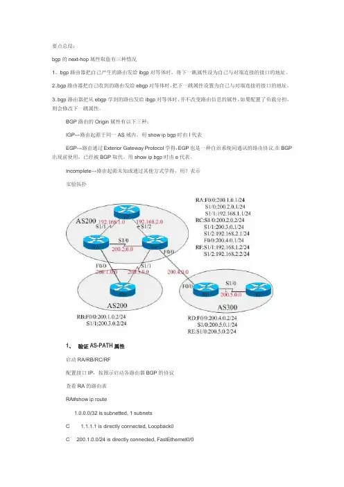
要点总结:bgp的next-hop属性取值有三种情况1、bgp路由器把自己产生的路由发给ibgp对等体时,将下一跳属性设为自己与对端连接的接口的地址。
2、bgp路由器把自己收到的路由发给ebgp对等体时,把下一跳属性设置为自己与对端连接的接口的地址。
3、bgp路由器把从ebgp学到的路由发给ibgp对等体时,并不改变路由信息的属性。
如果配置了负载分担,则会修改下一跳属性。
BGP路由的Origin属性有以下三种:IGP---路由起源于同一AS域内,用show ip bgp时由I代表EGP---路由通过Exterior Gateway Protocol学得,EGP也是一种自治系统间通讯的路由协议,在BGP 出现前使用,已经被BGP取代。
用show ip bgp时由e代表。
Incomplete---路由起源未知或通过其他方式学得,用?表示实验拓扑1、验证AS-PATH属性启动RA/RB/RC/RF配置接口IP,按图示启动各路由器BGP的协议查看RA的路由表RA#show ip route1.0.0.0/32 is subnetted, 1 subnetsC 1.1.1.1 is directly connected, Loopback0C 200.1.0.0/24 is directly connected, FastEthernet0/0C 200.2.0.0/24 is directly connected, Serial1/0B 200.3.0.0/24 [200/0] via 200.2.0.2, 00:01:37C 192.168.1.0/24 is directly connected, Serial1/1B 192.168.2.0/24 [200/0] via 200.2.0.2, 00:01:37红色字第一条,RA到200.3.0.0网段的下一跳是RC,而不是用快速以太网链路连接的RB。
![CCNP之BGP试验案例[优质文档]](https://uimg.taocdn.com/8a4c44542f3f5727a5e9856a561252d380eb20c3.webp)
CCNP之BGP实验案例实验需求:1、每一台路由器都起一个/32的回环地址,用来建立BGP邻居关系2、大型企业内部起OSPF协议,ISP B内部也起OSPF协议,企业A分别和ISP B和ISP C建立BGP邻接关系,以用来透传互联网上的条目3、要求ISP C学到挂在ISP B的服务器条目尽可能少4、要求ISP C前往ISP B那些服务器是通过R3和R5之间的高带宽链路,为了充分利用带宽,要求ISP B访问ISP C上的服务器是走的R4和R6之间的低带宽链路,这些配置都需要在大型企业上完成5、要求ISP和企业之间建立的BGP邻接是安全的6、完成配置之后,确信网络中每一台设备都学到了服务器对应的BGP条目实验拓扑图:实验步骤:1、在大型企业A和ISP B内部起OSPF协议R2:R2(config)#router ospf 1R2(config-router)#net 2.2.2.2 0.0.0.0 a 0R2(config-router)#net 23.23.23.23 0.0.0.0 a 0R2(config-router)#net 24.24.24.24 0.0.0.0 a 0R3:R3(config)#router ospf 1R3(config-router)#net 3.3.3.3 0.0.0.0 a 0R3(config-router)#net 23.23.23.1 0.0.0.0 a 0R4:R4(config)#router ospf 1R4(config-router)#net 4.4.4.4 0.0.0.0 a 0R4(config-router)#net 24.24.24.1 0.0.0.0 a 0R5:R5(config)#router ospf 1R5(config-router)#net 5.5.5.5 0.0.0.0 a 0R5(config-router)#net 57.57.57.2 0.0.0.0 a 0R6:R6(config)#router ospf 1R6(config-router)#net 6.6.6.6 0.0.0.0 a 0R6(config-router)#net 67.67.67.2 0.0.0.0 a 0R7:R7(config)#router ospf 1R7(config-router)#net 7.7.7.7 0.0.0.0 a 0R7(config-router)#net 57.57.57.1 0.0.0.0 a 0R7(config-router)#net 67.67.67.1 0.0.0.0 a 02、全网启用BGP协议由于ebgp建立在TCP连接的基础上,所以需要配置静态路由。
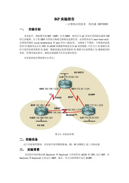
BGP实验报告—计算机应用技术周昌盛 20070305 一、实验目标本实验中,将配置内部BGP(IBGP)以及EBGP,使用公司AS内部不同的路由器到ISP的冗余链路。
为了使IBGP对等体正确地交换路由选择信息,必须使用命令next-hop-self。
还要使用属性local-preference和med(多出口描述符),这确保了平缓的、不限量的流量使用T1链路发送去往ISP1的AS200的数据和接收从该AS来的数据。
只有当主T1链路失效时才使用流量受限的T1链路。
数据流通过流量受限的T1链路可以获得跟主T1链路相同的带宽,但费用就高得多,确保这条链路不在非必要时使用。
本实验的拓扑图如图1-1所示:图1-1 实验拓扑图二、实验设备由于实验条件限制,本实验中使用模拟器R1、R2、R3来模拟上述三台路由器三、实验背景本实验中将在路由器SanJose1和SanJose2与外部邻局AS200的ISP1运行BGP,在SanJose1和SanJose2之间运行IBGP。
最后,在公司的网络中运行EIGRP。
四、实验步骤步骤1配置路由器ISP1的接口:Router>enRouter#config tRouter<config>#hostname ISP1ISP1<config>#interface loopback0ISP1<config-if>#ip add 192.168.100.1 255.255.255.0ISP1<config-if>#no shutISP1<config-if>#interface f1/0ISP1<config-if>#ip add 192.168.1.1 255.255.255.252ISP1<config-if>#no shutISP1<config-if>#interface f0/0ISP1<config-if>#ip add 192.168.1.5 255.255.255.252ISP1<config-if>#no shutISP1<config-if>#end配置路由器SanJose1的接口:Router>enRouter#config tRouter<config>#hostname SanJose1SanJose1<config>#interface loopback0SanJose1<config-if>#ip add 172.16.64.1 255.255.255.0 SanJose1<config-if>#no shutSanJose1<config-if>#interface f1/0SanJose1<config-if>#ip add 192.168.1.6 255.255.255.252 SanJose1<config-if>#no shutSanJose1<config-if>#interface f0/0SanJose1<config-if>#ip add 172.16.1.1 255.255.255.0 SanJose1<config-if>#no shutSanJose1<config-if>#end配置路由器SanJose2的接口:Router>enRouter#config tRouter<config>#hostname SanJose1SanJose2<config>#interface loopback0SanJose2<config-if>#ip add 172.16.32.1 255.255.255.0 SanJose2<config-if>#no shutSanJose2<config-if>#interface f1/0SanJose2<config-if>#ip add 172.16.1.2 255.255.255.252 SanJose2<config-if>#no shutSanJose2<config-if>#interface f0/0SanJose2<config-if>#ip add 192.168.1.2 255.255.255.252 SanJose2<config-if>#no shutSanJose2<config-if>#end上述配置完成后,可以使用ping命令来测试直连路由之间的连通性。
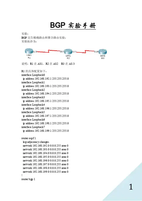
BGP实验手册实验:BGP宣告精确路由和聚合路由实验:实验拓扑为:说明:R1在AS1,R2在AS2 R3在AS 3R1的具体配置如下:interface Loopback0ip address 192.168.192.1 255.255.255.0interface Loopback1ip address 192.168.193.1 255.255.255.0interface Loopback2ip address 192.168.194.1 255.255.255.0interface Loopback3ip address 192.168.195.1 255.255.255.0interface Loopback4ip address 192.168.196.1 255.255.255.0interface Loopback5ip address 192.168.197.1 255.255.255.0interface Loopback6ip address 192.168.198.1 255.255.255.0interface Loopback7ip address 192.168.199.1 255.255.255.0router ospf 1log-adjacency-changesnetwork 192.168.192.0 0.0.0.255 area 0network 192.168.193.0 0.0.0.255 area 0network 192.168.194.0 0.0.0.255 area 0network 192.168.195.0 0.0.0.255 area 0network 192.168.196.0 0.0.0.255 area 0network 192.168.197.0 0.0.0.255 area 0network 192.168.198.0 0.0.0.255 area 0network 192.168.199.0 0.0.0.255 area 0!router bgp 1aggregate-address 192.168.192.0 255.255.248.0 聚合路由redistribute ospf 1 实验采用重分布,但是实际不建议这样。

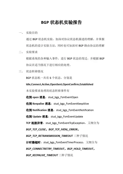
BGP状态机实验报告一、实验目的通过BGP状态机实验,加深对协议状态机描述的理解,并掌握状态机的设计实验方法,同时也可加深对BGP路由协议的理解二、实验要求根据系统的各种输入事件,进行BGP状态的变迁,并根据BGP 协议在适当情况下进行相应的处理。
三、状态转移情况BGP状态机一共有6个状态,分别是Idle,Connect,Active,OpenSent,OpenConfirm,Established本实验要求处理的状态转移事件有收到open消息:stud_bgp_FsmEventOpen收到Keepalive消息:stud_bgp_FsmEventKeepAlive收到Notification消息:stud_bgp_FsmEventNotification收到Update消息:stud_bgp_FsmEventUpdateTCP连接异常:stud_bgp_FsmEventTcpException,又细分为BGP_TCP_CLOSE,BGP_TCP_FATAL_ERROR,BGP_TCP_RETRANSMISSION_TIMEOUT三种子情况计时器超时:stud_bgp_FsmEventTimerProcess,又细分为BGP_CONNECTRETRY_TIMEOUT,BGP_HOLD_TIMEOUT,BGP_KEEPALIVE_TIMEOUT三种子情况BGP开始:stud_bgp_FsmEventStartBGP结束:stud_bgp_FsmEventStop收到连接结果:stud_bgp_FsmEventConnect整理后的状态转移表如下编程时,只要在事件处理函数中完成对应状态的变换即可四、包的发送1.open将BGP消息头的标记全部置为1,表示不包含认证信息●设置长度●设置消息类型●设置版本●设置自治系统号●设置保持时间●设置BGP标志符●调用bgp_FsmSendTcpData函数发送包2.notification●BGP消息头的标记全部置为1●设置BGP消息头的长度●设置BGP消息头的类型●设置NOTIFICATION消息的错误编码●设置NOTIFICATION消息的错误字码●调用bgp_FsmSendTcpData函数发送包3.keepalive●BGP消息头的标记全部置为1●设置BGP消息头的长度●设置BGP消息头的类型●调用TCP段发送函数bgp_FsmSendTcpData发送五、遇到的问题●包头的格式marker要设置为全一,表示不包含认证信息。

网络工程综合实验实验报告课程名称网络工程综合实验实验名称_____ BGP和GRE实验_____学生学院自动化学院 ___专业班级__ 网络一班_________学号3108001217学生姓名_______ 李亮 _____指导教师________张钢 _______2011 年12 月一.实验目的1.掌握BGP路由协议的配置方法2.掌握GRE隧道协议的配置方法和应用场景3.掌握在复杂网络环境中的多协议配置和排错技巧二.实验原理和拓扑本实验的拓扑结构图如图2.1所示:图2.1 BGP & GRE的拓扑结构图三.实验内容说明和要求:A.S1、S2、S3为H3C的可配置交换机,请为每台交换机配置一个同网段的管理IP地址(172.16.254.*/24),并配置交换机的telnet远程登录。
三台交换机之间通过两条端口聚合的通道相连。
B.S S1和SS2为3COM的简单交换机,在本实验中作为HUB使用。
C.请取消所有交换机上的VLAN划分的配置。
D.为路由器配置telnet的远程登录。
E.本实验的配置目标有两个,第一是配置一个BGP的路由网络,外部BGP使用BGPv4,内部BGP使用OSPF作为路由协议。
第二个是配置R2和R3之间的GRE Tunnel,使R2和R3后面的两个子网能够通过这个通道连成一个虚拟的大子网。
F.把每台设备改名为图中的名字(如S1、S2、S3、R1、SS1等),以便识别。
R1和R7上不启动BGP协议,使用缺省路由指明出口为R2的串行口和R3的串行口。
G.R2、R3、R4、R5、R6上启动BGP协议。
H.请自行规划每一个网段和路由器上每个接口的地址和子网掩码。
I.在R2和R3上配置DHCP服务器,并且要求两个DHCP服务器的地址池不能设置为同一网段。
在R1/R7上设置DHCP中继,使R1/R7可以转发R2/R3的DHCP数据包给R1/R7的以太网口所连接的网段的主机。
J.在R2和R3之间开启一条GRE Tunnel,R2与R3后面的子网能够通过GRE Tunnel连成一个子网(能够相互访问)。

38个BGP实验汇总38个BGP实验汇总1.实验1说明:BGP的同步2.实验2 BGP环回接口实验3.实验3语法: Neighbor ip address /peer-group-name ebgp-multihop作用:Ebgp邻居一般情况下直连,如果不是直连,可通过这个命令来修改。
值为1-255如果不指定,默认为255 注意:如果要用多跳,一定要注意下一跳可达。
4.实验4语法:Neighbor ip address /peer-group-name next-hot-self作用:在非广播多路访问时,有时有必要将下一跳改为自己.在下面的实验中,将从a 传过来的路由条目改为自己5.实验6语法:Neighbor ip address/peer-group-name advertisementinterval seconds作用:修改bgp触发时间。
如果邻居是ibgp 则修改ibgp时间,如果是 ebgp则会修改ebgp时间了。
默认情况下,ibgp为5秒,ebgp为30秒。
这是路由更新的最少时间。
原因,就是:当路由条目在一定时间闪动多次时,也只有到了最少触发时间才会发出触发更新。
一般情况下,不必要修改。
但是注意这个时间是可以修改的以行。
6.实验7语法:Neighbor ip address/peer-grouup-name timers keepalive holdtime作用:用来修改bgp的存活时间与保持时间,默认为60秒与 180秒。
一般情况下不用修改。
7.实验8语法:BGP实验1 路由汇总Aggregate-address + address maskAggregate-address +上需要汇总的地址和掩码实验二Aggregate-address + address mask也可以用于接收路由器进行汇合。
实验三Aggregate-address + address mask+as-set 作用:来明确路由信息的as路径。
Bgp实验报告
1 路由协议相互引入
2 bgp属性设置
3 bgp同步设置
4 bgp反射器
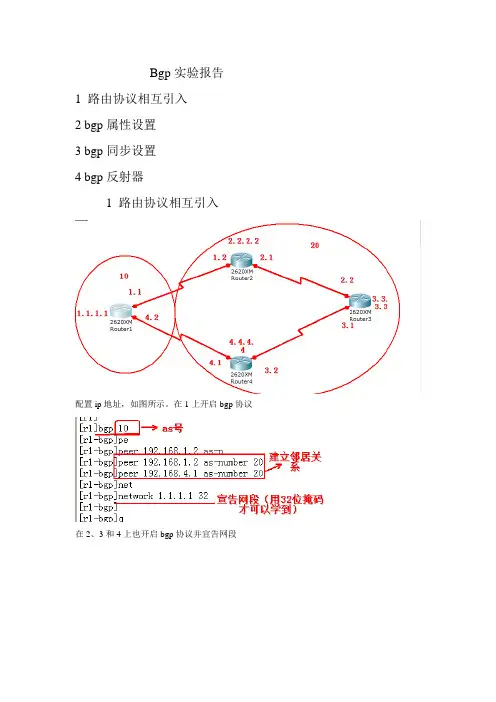
1 路由协议相互引入
配置ip地址,如图所示。
在1上开启bgp协议
在2、3和4上也开启bgp协议并宣告网段
查看路由情况
因为内部没有开启协议,不知道路怎么走。
所以不能建立关系,要在20内部开启协议这里开ospf
在次查看邻居关系
查看路由情况
用ping命令测试一下
在2上宣告网段(也可以引入直连)
再次用ping命令测试
2 bgp属性设置本地优先级
在4上修改本地优先级
在3上查看路由情况
修改med值
先从1上查看路由情况
在2和4上都修改med值
再次查看路由
Med值越小。
优先走这条路
修改首选值
先在1上查看路由
在1修改首选值
查看路由情况
3 bgp同步
如图配置ip地址并开启协议宣告网段(这里只在4上和5建立关系就行了)
在5上开启协议
查看路由条目
在2和4上开启同步
查看路由情况
同步是把都有的往下传递,没有的则不传递相互引入路由
查看路由条目
在4上也引入路由
查看路由
在引入直连网络,1和5就都可以学到全部的路由了
4 反射器
在20里面的2 4 5都开启内部路由协议和3建立关系
在3上先建立关系
查看下路由
和其他建立关系
在建立客户端
查看路由情况
反射器从客户端学到的地址要发给其他客户端和非客户端,从非客户端学到的要发给客户端,客户端之间不能相互学习,要通过反射器才能学到。

mininet实验-BGP和OSPF路由协议一、自治系统自治系统AS(Autonomous System):自治系统就是几个路由器组成了一个小团体,小团体内部使用专用的协议进行通信,而小团体和小团体之间也使用专用的协议进行通信。
就像这样一样:值得一提的是,尽管一个AS内部使用了路由选择协议,但是一个AS对其他AS还是相当于两个普通的路由器在通信。
二、路由选择协议互联网中有两大类路由选择协议,他们分别是:1️⃣内部网关协议IGP(Interior Gateway Protocol)2️⃣外部网关协议EGP(External Gateway Protocol)其中内部网关协议就是我们之前说的在路由器的小团体之间进行通信所使用的协议,如RIP和OSPF等。
而外部网关协议则是小团体与小团体之间交流所使用的协议,目前使用的协议就是BGP。
到此为止我们要讲述的猪脚就登场了!自治系统之间的路由选择也叫作域间路由选择(interdomain routing),在自治系统内部的路由选择叫作域内路由选择(intradomain routing)。
三、内部网关协议RIP好了,下面我们进入第一块内容RIP协议。
1、工作原理全称是路由信息协议RIP(Routing Information Protocol)。
✅它是一种分布式的、基于距离向量的路由选择协议。
✅它要求网络中的每一个路由器都要维护从它自己到其他每一个目的网络的距离记录。
关于距离的定义:从一个路由器到直接连接的网络的距离定义为1。
从一个路由器到非直接连接的网络的距离定义为所经过的路由器数加1。
“距离”也称为“跳数”(hop count),因为每经过一个路由器,跳数就加1。
这里的“距离”实际上指的是“最短距离”。
RIP认为一个好的路由就是它通过的路由器的数目少,即“距离短”。
RIP允许一条路径最多只能包含15个路由器。
❌这意味着RIP只会选择一个具有最少路由器的路由(即最短路由),哪怕还存在另一条高速(低时延)但路由器较多的路由。
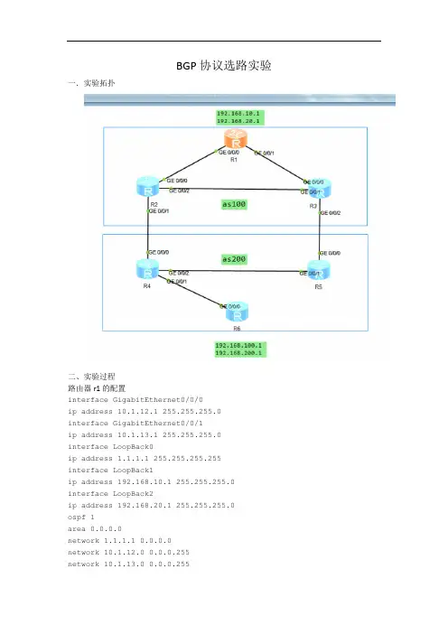
BGP协议选路实验一.实验拓扑二、实验过程路由器r1的配置interface GigabitEthernet0/0/0ip address 10.1.12.1 255.255.255.0interface GigabitEthernet0/0/1ip address 10.1.13.1 255.255.255.0interface LoopBack0ip address 1.1.1.1 255.255.255.255interface LoopBack1ip address 192.168.10.1 255.255.255.0 interface LoopBack2ip address 192.168.20.1 255.255.255.0ospf 1area 0.0.0.0network 1.1.1.1 0.0.0.0network 10.1.12.0 0.0.0.255network 10.1.13.0 0.0.0.255bgp 100peer 2.2.2.2 as-number 100peer 2.2.2.2 connect-interface LoopBack0peer 3.3.3.3 as-number 100peer 3.3.3.3 connect-interface LoopBack0 network 192.168.10.0network 192.168.20.0路由器r2的配置interface GigabitEthernet0/0/0ip address 10.1.12.2 255.255.255.0interface GigabitEthernet0/0/1ip address 10.1.23.2 255.255.255.0interface GigabitEthernet0/0/2ip address 10.1.24.2 255.255.255.0interface LoopBack0ip address 2.2.2.2 255.255.255.255ospf 1area 0.0.0.0network 10.1.12.0 0.0.0.255network 10.1.23.0 0.0.0.255network 2.2.2.2 0.0.0.0acl number 2000rule 5 permit source 192.168.200.0 0.0.0.255 route-policy 1 permit node 10if-match acl 2000apply local-preference 500route-policy 1 permit node 20bgp 100peer 1.1.1.1 as-number 100peer 1.1.1.1 connect-interface LoopBack0peer 3.3.3.3 as-number 100peer 3.3.3.3 connect-interface LoopBack0peer 10.1.24.4 as-number 200peer 1.1.1.1 next-hop-localpeer 3.3.3.3 route-policy 1 importpeer 3.3.3.3 next-hop-local路由器r3的配置interface GigabitEthernet0/0/0ip address 10.1.13.3 255.255.255.0interface GigabitEthernet0/0/1ip address 10.1.23.3 255.255.255.0interface GigabitEthernet0/0/2ip address 10.1.35.3 255.255.255.0interface LoopBack0ip address 3.3.3.3 255.255.255.255ospf 1area 0.0.0.0network 10.1.13.0 0.0.0.255network 10.1.23.0 0.0.0.255network 3.3.3.3 0.0.0.0acl number 2000rule 5 permit source 192.168.100.0 0.0.0.255 route-policy 1 permit node 10if-match acl 2000apply local-preference 500route-policy 1 permit node 20bgp 100peer 1.1.1.1 as-number 100peer 1.1.1.1 connect-interface LoopBack0peer 2.2.2.2 as-number 100peer 2.2.2.2 connect-interface LoopBack0peer 10.1.35.5 as-number 200peer 1.1.1.1 next-hop-localpeer 2.2.2.2 route-policy 1 importpeer 2.2.2.2 next-hop-local路由器r4的配置interface GigabitEthernet0/0/0ip address 10.1.24.4 255.255.255.0interface GigabitEthernet0/0/1ip address 10.1.45.4 255.255.255.0interface GigabitEthernet0/0/2ip address 10.1.46.4 255.255.255.0interface LoopBack0ip address 4.4.4.4 255.255.255.255ospf 1area 0.0.0.0network 4.4.4.4 0.0.0.0network 10.1.45.0 0.0.0.255network 10.1.46.0 0.0.0.255acl number 2000rule 5 permit source 192.168.20.0 0.0.0.255 route-policy 1 permit node 10if-match acl 2000apply as-path 10 20 30 additiveroute-policy 1 permit node 20bgp 200peer 5.5.5.5 as-number 200peer 5.5.5.5 connect-interface LoopBack0peer 6.6.6.6 connect-interface LoopBack0 peer 10.1.24.2 as-number 100peer 5.5.5.5 next-hop-localpeer 6.6.6.6 next-hop-localpeer 10.1.24.2 route-policy 1 import路由器r5的配置interface GigabitEthernet0/0/0ip address 10.1.35.5 255.255.255.0interface GigabitEthernet0/0/1ip address 10.1.45.5 255.255.255.0interface LoopBack0ip address 5.5.5.5 255.255.255.255acl number 2000rule 5 permit source 192.168.10.0 0.0.0.255 route-policy 1 permit node 10if-match acl 2000apply as-path 10 20 30 additiveroute-policy 1 permit node 20bgp 200peer 4.4.4.4 as-number 200peer 4.4.4.4 connect-interface LoopBack0 peer 6.6.6.6 as-number 200peer 6.6.6.6 connect-interface LoopBack0 peer 10.1.35.3 as-number 100peer 4.4.4.4 next-hop-localpeer 6.6.6.6 next-hop-localpeer 10.1.35.3 route-policy 1 import路由器r6的配置interface GigabitEthernet0/0/0ip address 10.1.46.6 255.255.255.0interface LoopBack0ip address 6.6.6.6 255.255.255.255interface LoopBack1ip address 192.168.100.1 255.255.255.0 interface LoopBack2ip address 192.168.200.1 255.255.255.0ospf 1area 0.0.0.0network 6.6.6.6 0.0.0.0network 10.1.46.0 0.0.0.255bgp 200peer 4.4.4.4 as-number 200peer 4.4.4.4 connect-interface LoopBack0peer 5.5.5.5 connect-interface LoopBack0 network 192.168.100.0network 192.168.200.0实验结果查看流量路径。
BGP属性(本地优先和MED)验证实验实验名称:BGP属性(本地优先和MED)验证实验实验目的:通过本实验验证了解BGP属性(本地优先和MED)。
实验拓扑:见下图实验要求:1、R1/R2/R3上运行EIGRP协议,R4/R5 上运行RIP协议。
2、11.0.0.1/24,16.0.0.2/24,13.0.0.3/24,14.0.0.4/24,15.0.0.5/24与10.0.0.1/24,20.0.0.2/24,30.0.0.0/24,40.0.0.4/24,50.0.0.5/24相互可以PING通。
3、通过本地优先属性使得在R2通往11.0.0.1/24,,16.0.0.2/24,13.0.0.3/24,14.0.0.4/24,15.0.0.5/24网络时,11.0.0.1/24、16.0.0.6/24分别走R3,其余的走R1.4、通过MED属性使得R4通往10.0.0.1/24,20.0.0.2/24,30.0.0.0/24,40.0.0.4/24,50.0.0.5/24网络时,10.0.0.1/24,20.0.0.2/24,的下一跳是1.1.1.1,而40.0.0.4/24,50.0.0.5/24的下一跳是3.3.3.3,30.0.0.0/24不变。
实验分析:1、在R1/R3上配置去往R4的静态路由,在R4上配置去往R1/R3的静态路由,在R1/R2/R3配置EIGRP和R4/R5上配置RIP的的基础上,确保TCP可达,BGP各个邻居可以建立。
2、配置EBGP和IBGP邻居。
3、因为要对11.0.0.1/24,,16.0.0.2/24,13.0.0.3/24,14.0.0.4/24,15.0.0.5/24和10.0.0.1/24,20.0.0.2/24,30.0.0.0/24,40.0.0.4/24,50.0.0.5/24进行操纵,所以要使用ACL。
4、对ACL操纵的网络使用ROUTER –MAP进行控制、并在NEIghbor下调用。
BGP协议的测试实验运维进阶【作者】王巧雷,拥有多年⼀线实战经验的运维⼈。
1、基本概念描述⼀些前置知识:1. BGP的全称是border gateway protocol,是⽤在AS之间的协议。
2. AS是Autonomous system的简称,可以理解为运⾏同⼀种选路策略、统⼀管理的⼀组路由器。
3. 每个AS都有⼀个AS number,取值范围为 1-65535 ,其中1-64511是公有的,需要向IANA申请, 64512-65535是私有的可以⾃由使⽤,类似192.168的IP地址。
4. 跨AS的是EBGP,AS内的是IBGP。
5. BGP是基于tcp做的封包,可以理解为bgp的包头外⾯会由tcp封包,tcp外⾯由IP封包,然后然后是⼆层的包头。
在⽹络中传输。
关于路由⿊洞:以2.1的拓扑图为例:pc1的192.168.1.10对pc2的172.16.30.10做ping测试,就需要有路由信息。
路由信息封装在bgp中,从R4到R5的链路中,R1没有运⾏bgp,当bgp的数据包传输的时候,因为是基于tcp封装的,bgp信息依次被tcp、ip、解决路由⿊洞的⽅法有好⼏种,⽐如:物理线路的full mesh,也就是说将as内的边缘路由器连线将BGP重分布进OSPFAS内所有路由器都运⾏bgp(本次实验采⽤的)使⽤MPLS做tunnel2. 测试过程本次实验是采⽤GNS3模拟器做的,采⽤了IOU设备的⽅式。
模拟了bgp的实现过程,顺便验证了⼀下BGP中的路由⿊洞。
2.1 测试拓扑拓扑解释:R1、R2、R3为⼀个⾃治区域,号码为123,为ibgp,3台路由器之间运⾏ospf,R2和R3运⾏bgp,R1仅运⾏ospfR4为⼀个⾃治区域,号码为4,和R123之间为ebgpR5为⼀个⾃治区域,号码为5,和R123之间为ebgp各⾃路由器的router id为路由器编号地址,⽐如R1的为1.1.1.12.2 R1、R2、R3配置IP,配置ospf1、配置IP地址R1配置IP:R1#conf tEnter configuration commands, one per line. End with CNTL/Z.R1(config)#int s2/0R1(config-if)#ip add 12.1.1.2 255.255.255.0R1(config-if)#no shuR1(config-if)#exitR1(config)#int s2/1R1(config-if)#ip add 11.1.1.1 255.255.255.0R1(config-if)#no shuR2配置IP:R2#conf tEnter configuration commands, one per line. End with CNTL/Z.R2(config)#int s2/0R2(config-if)#ip add 14.1.1.2 255.255.255.0R2(config-if)#no shuR2(config-if)#exitR2(config)#int s2/1R2(config-if)#ip add 12.1.1.1 255.255.255.0R2(config-if)#no shuR3配置IP:R3#conf tEnter configuration commands, one per line. End with CNTL/Z.R3(config)#int s2/0R3(config-if)#ip add 11.1.1.2 255.255.255.0R3(config-if)#no shuR3(config-if)#exitR3(config)#int s2/1R3(config-if)#ip add 13.1.1.1 255.255.255.0R3(config-if)#no shu2、配置ospf,对于R2和R3来说,只配置AS内的接⼝,外联ebgp的⼝不配置到ospf中R1配置R1(config)#router ospf 110R1(config-router)#router-id 1.1.1.1R1(config-router)#net 12.1.1.2 0.0.0.0 area 0R1(config-router)#net 11.1.1.1 0.0.0.0 area 0R2配置R2(config)#router ospf 110R2(config-router)#router-id 2.2.2.2R2(config-router)#net 12.1.1.1 0.0.0.0 area 0R3配R3(config)#router ospf 110 R3(config-router)#router-id 3.3.3.3R3(config-router)#network 11.1.1.2 0.0.0.0 area 03、查看路由表信息R2#show ip route Codes: L - local, C - connected, S - static, R - RIP, M - mobile, B - BGP D - EIGRP, EX - EIGRP external, O - OSPF, IA - OSPF inter area N1 - OSPF NSSA external type 1, N2 - OSPF NSSA external type 2 E1 - OSPF external type 1, E2 - O 查看ospfR2#show ip ospf database OSPF Router with ID (2.2.2.2) (Process ID 110) Router Link States (Area 0)Link ID ADV Router Age Seq# Checksum Link count1.1.1.1 1.1.1.1 178 0x80000005 0x00A804 42.3 配置bgp这部分分为ibgp和ebgp的2.3.1 为as123配置ibgp1、在R2配置bgp协议R2(config)#router bgp 123R2(config-router)#bgp router-id 2.2.2.2R2(config-router)#neighbor 11.1.1.2 remote-as 123 //为bgp指定邻居,这⾥指定的是本as内R3的s2/0R2(config-router)#*Feb 29 15:43:36.408: %BGP-5-ADJCHANGE: neighbor 11.1.1.2 Up //等待⽚刻,2、在R3配置bgp协议R3(config)#router bgp 123R3(config-router)#bgp router-id 3.3.3.3R3(config-router)#neighbor 12.1.1.1 remote-as 123R3(config-router)#neighbor 13.1.1.2 remote-as 53、查看bgp信息,因为as4和5的IP和bgp还没配置,所以邻居部分的显⽰不正常R2执⾏查看R2#show ip bgp summary BGP router identifier 2.2.2.2, local AS number 123BGP table version is 1, main routing table version 1Neighbor V AS MsgRcvd MsgSent TblVer InQ OutQ Up/Down State/PfxRcd11.1.1.2 4 123 9 9 1 0 0 00:04:47 014.1.1.1R3执⾏查看R3#show ip bgp summary BGP router identifier 3.3.3.3, local AS number 123BGP table version is 1, main routing table version 1Neighbor V AS MsgRcvd MsgSent TblVer InQ OutQ Up/Down State/PfxRcd12.1.1.1 4 123 9 10 2.3.2 为AS4和5配置ebgp1、⾸先配置R4和5的IP地址R4的地址R4#conf tEnter configuration commands, one per line. End with CNTL/Z.R4(config)#int s2/0 R4(config-if)#ip add 14.1.1.1 255.255.255.0R4(config-if)#no shuR4(config-if)#exitR4(config)#int e0/0R4(config-if)#ip add 192.168.1.1 255.255.255.0 R4(config-if)#no shuR5的地址R5#conf tEnter configuration commands, one per line. End with CNTL/Z.R5(config)#int s2/0R5(config-if)#ip add 13.1.1.2 255.255.255.0R5(config-if)#no shuR5(config-if)#exitR5(config)#int e0/0R5(config-if)#ip add 172.16.30.1 255.255.255.0R5(config-if)#no shu 2、为R4配置bgpR4(config)#router bgp 4R4(config-router)#bgp router-id 4.4.4.4R4(config-router)#neighbor 14.1.1.2 remote-as 123 //指定as123中R2的s2/0为邻居R4(config-router)#*Feb 29 15:54:02.133: %BGP-5-ADJCHANGE: neighbor 14.1.1.2 Up //邻居建⽴提⽰3、为R5配置bgpR5(config-router)#bgp routerR5(config-router)#bgp router-id 5.5.5.5R5(config-router)#neighbor 13.1.1.1 remote-as 1234、查看bgp信息R4#show ip bgp summary BGP router identifier 4.4.4.4, local AS number 4BGP table version is 1, main routing table version 1Neighbor V AS MsgRcvd MsgSent TblVer InQ OutQ Up/Down State/PfxRcd14.1.1.2 4 123 6 6 1 0 0 00:02:38 0此时再看R2或者R3的bgp信息,邻居关系就都正常了R2#show ip bgp summary BGP router identifier 2.2.2.2, local AS number 123BGP table version is 1, main routing table version 1Neighbor V AS MsgRcvd MsgSent TblVer InQ OutQ Up/Down State/PfxRcd11.1.1.2 4 123 19 18 2.3.3 在as4的路由R4 宣告路由192.168.1.0这⾥是要将pc1的192.168.1.0/24这个⽹络宣告到bgp中,步骤如下1、在R4上宣告路由R4(config)#router bgp 4R4(config-router)#network 192.168.1.0 mask 255.255.255.0 //只能宣告⽹段,指定掩码查看bgp 路由信息R4#show ip bgp BGP table version is 2, local router ID is 4.4.4.4Status codes: s suppressed, d damped, h history, * valid, > best, i - internal, r RIB-failure, S Stale, m multipath, b backup-path, f RT-Filter, x best-external, a additional-path, c R 本地产⽣,下⼀跳为0.0.0.02、此时到R2上查看bgp信息,发现路由信息已经过来了,且可以看到192.168.1.0⽹段的下⼀跳为14.1.1.1(R4的S2/0,出⼝接⼝)R2#show ip bgpBGP table version is 2, local router ID is 2.2.2.2Status codes: s suppressed, d damped, h history, * valid, > best, i - internal, r RIB-failure, S Stale, m multipath, b backup-path, f RT-Filter, x best-external, a additional-path, c RIB-compressed,R2上也能看到路由信息,可以看到192.168.1.0是通过bgp学习到的,metric是20,通过ebgp学习到的路由条⽬metric都是20,如果是ibgp则为200R2#show ip route Codes: L - local, C - connected, S - static, R - RIP, M - mobile, B - BGP D - EIGRP, EX - EIGRP external, O - OSPF, IA - OSPF inter area N1 - OSPF NSSA external type 1, N2 - OSPF NSSA external type 2 E1 - OSPF external 3、再看R3上的bgp信息,发现下⼀跳还是R4上的s2/0,⽽且路由条⽬前⾯没有>,不是最优路由,说明没有把信息传过来,ibgp传输路由信息的时候不会传输下⼀跳的地址R3#show ip bgpBGP table version is 1, local router ID is 3.3.3.3Status codes: s suppressed, d damped, h history, * valid, > best, i - internal, r RIB-failure, S Stale, m multipath, b backup-path, f RT-Filter, x best-external, a additional-path, c RIB-compressed,需要在R2路由上添加next-hop-self,才会把下⼀跳的信息传递过来。
目录前言: (1)一、测试总结 (1)二、测试用例 (2)三、测试步骤 (3)3.1占用Ports (3)3.2配置IP地址 (4)3.3配置BGP (6)3.4发布BGP Route (12)3.5配置流量 (15)3.6启用BGP (18)3.7发流验证 (20)前言:当前信息化时代之下,数据传输已经成为了日常工作和生活必不可少的重要组成部分,网络服务的易得性和可靠性也因此得到广泛关注。
这其中负责网络正常工作的诸多协议,作为保证网络数据传输的有力支持,也成为了研究的重点对象。
另外,随着网络发展的日益成熟,相应的拓扑结构以及网络自治域也随之呈现出日益复杂的特征,一方面自治域内部呈现出相对独立的特征,另一个方面期间的通信却呈现出越来越频繁的特征,而且对于通信质量的要求也有显著提升趋势,所有的这些都使得BGP协议的地位日益重要。
阅读并学习完本文后,您将获得:1.熟知并掌握BGP协议原理;2.了解协议的内在运行机制;3.通过典型用例进行实操联系,加深对协议的理解;4.同时熟悉仪表的操作方式。
一、测试总结本篇文章的实验思路如下所示:1.在port上创建接口,配置IPV4地址;2.配置向导中选择BGP协议仿真;3.选择端口-配置AS号码;4.配置BGP路由;5.配置交换机:配置接口IP地址、配置BGP AS、创建Peer、绑定接口;通过实现以上思路并进行配置,您将获得以下测试结果:1.仪表BGP协议仿真状态为Running;2.协议会话统计结果有报文收发;3.交换机BGP邻居状态为ESTABLISHED、BGP路由表接收仪表发来的BGP路由;实验结果说明:交换机BGP邻居状态为ESTABLISHED,说明仪表和交换机之间的BGP邻居关系已建立成功,交换机BGP路由表有IPV4路由说明仪表成功发布了BGP路由,由此验证了BGP的协议会话和路由发布功能;接下来为您演示使用信而泰网络测试仪配套测试软件“RENIX”进行BGP协议测试实操。
75LAB O BJECTIVEST he objective of this lab is to simulate and study the basic features of an interdomain routing protocol called Border Gateway Protocol (BGP).O VERVIEWT he Internet is organized as a set of routing domains. Each routing domain is called an a utonomous system (AS). Each AS is controlled by a single administrative entity (e.g., an AS of a single service provider). Each AS has a unique 16-bit identifi cation number. This number is assigned by a central authority. An AS uses its own intradomain routing protocol (e.g., RIP or OSPF). An AS establishes routes with other ASs through interdomain routing protocols. The Border Gateway Protocol (BGP) is one of the well-known interdomain routing protocols. T he main goal of BGP is to fi nd any path to the destination that is loop-free. This is different from the common goal of intradomain routing protocols, which is to fi nd an optimal route to the destination based on a specifi c link metric. The routers that connect different ASs are called b order gateways . The task of the border gateways is to forward packets between ASs. Each AS has at least one BGP speaker. BGP speakers exchange reachability information among ASs. B GP advertises the complete path to the destination AS as an enumerated list. In this way, routing loops can be avoided. A BGP speaker can also apply some policies such as balancing the load over the neighboring ASs. If a BGP speaker has a choice of several different routes to a destination, it will advertise the best one according to its own local policies. BGP is defi ned to run on top of TCP, and hence BGP speakers do not need to worry about acknowledging received information or retransmission of sent information.I n this lab, you will set up a network with three different ASs. RIP will be used as the intra-domain routing protocol and BGP as the interdomain routing protocol. You will analyze the routing tables generated in the routers as well as the effect of applying a simple policy. P RE-LAB ACTIVITIES& Read Section 4.1.2 from C omputer Networks: A Systems Approach, 5th Edition . : Go to w and play the following animation:❍ I P Subnets B GP: Border GatewayProtocolA n Interdomain Routing Protocol876Network Simulation Experiments ManualP ROCEDUREC reate a New Project1. S tart O PNET IT Guru Academic Edition· Choose N ew from the F ile menu.2. S elect P roject and click O K· Name the project <your initials>_BGP, and the scenarioN o_BGP· Click O K.3. I n the S tartup Wizard: Initial Topology dialog box, make sure that C reate Empty Scenario isselected · Click N ext· Select E nterprise from the N etwork Scale list · Click N ext fourtimes · Click O K.C reate and Confi gure the Network1. T he O bject Palette dialog box should now be on top of your project workspace. If it is notthere, open it by clicking . Make sure that the i nternet_toolbox is selected from thepull-down menu on the object palette.2. A dd to the project workspace the following objects from the palette: six e thernet4_slip8_gtwyrouters and two 100BaseT_LAN objects.a. T o add an object from a palette, click its icon in the object palette · Move your mouseto the workspace · Click to place the object · Right-click to stop creating objects ofthat type.3. U se bidirectional P PP_DS3links to connect the routers you just added, as shown in thefollowing fi gure. Rename the objects as shown (right-click on the node ·S et Name).4. U se a bidirectional 100BaseT link to connect L AN_West to R outer1and another100BaseT link to connect L AN_East to R outer6as shown.5. C lose the O bject Palette dialog box ·S ave your project.T he e thernet4_slip8_gtwy node modelrepresents an IP-basedgateway support-ing four Ethernet hubinterfaces and eightserial line i nterfaces. IPpackets a rriving on anyinterface are routed tothe a ppropriate outputinterface based on theirdestination IP address.77LAB 8BGP: Border Gateway ProtocolR outers Confi guration1. R ight-click on any router · Click S elect Similar Nodes (make sure that all routers are selected) · Right-click on any router · E dit Attributes · Check the A pply Changes to Selected Objects check box.2. E xpand the B GP Parameters hierarchy and set the following:a . R edistribution · R outing Protocols · R IP · R edistribute w/ Default as shown. 3. E xpand the I P Routing Parameters hierarchy and set the following:a . R outing Table Export = O nce at End of Simulation . This asks the router to export its routing table at the end of the simulation to the s imulation log .4. E xpand the R IP Parameters hierarchy and set the following:a . R edistribution · R outing Protocols · D irectly Connected · R edistribute w/ Default .5. C lick O K , and then S ave your project.A pplication Confi guration1. R ight-click on L AN_West · E dit Attributes · Assign A ll to A pplication: Supported Services · Assign W est_Server to the L AN Server Name attribute as shown · Click O K . N otice that two objects for A pplications and P rofi les will be added automatically to the project.2. R ight-click on L AN_East · E dit Attributes :a . E xpand the A pplication: Supported Profi les hierarchy · Set r ows to 1 · Expand the r ow 0 hierarchy · Set P rofi le Name to E -commerce Customer . R edistribute w/ Default allows a router to have a route to a destination that belongs to another autonomous system . A pplication: Desti-nation Preferences p rovides mappingsb etween symbolicd estination names speci-fi ed in the Application Defi nition or Task Defi nition objects and real names specifi ed in Server Name or ClientName on each node.78Network Simulation Experiments Manualb . E dit the A pplication: Destination Preferences attribute as follows: Set r ows to 1 · Set S ymbolic Name to H TTP Server · Edit A ctual Name · Set r ows to 1 · In the new row, assign W est_ Server to the N ame column. 3. C lick O K three times, and S ave your project. C onfi gure the Simulation H ere, we need to confi gure some of the simulation parameters: 1. C lick on and the C onfi gure Simulation window should appear. 2. S et the duration to 10.0 minutes . 3. C lick on the G lobal Attributes tab and make sure that the following attributes are assigned as follows: a . I P Interface Addressing Mode = Auto Addressed/Export . b . I P Routing Table Export/Import = Export . c . R IP Sim Effi ciency = D isabled . If this attribute is enabled, RIP will stop after the “RIP Stop Time.” But we need the RIP to keep updating the routing table in case there is any change in the network.A uto Addressed meansthat all IP interfaces areassigned IP addressesautomatically duringsimulation. The class ofaddress (e.g., A, B, or C)is determined based onthe number of hosts inthe designed network.Subnet masks assignedto these interfaces arethe default subnet masksfor that class.79LAB 8BGP: Border Gateway ProtocolC hoose the Statistics 1. R ight-click on L AN_East and select C hoose Individual Statistics · From the C lient HTTP hierarchy choose the T raffi c Received (bytes/sec) statistic · Click O K . 2. R ight-click on the link that connects R outer2 to R outer3 and select C hoose Individual Statistics from the pop-up menu · From the p oint-to-point hierarchy choose the “ T hroughput (bits/sec) --> ” statistic · Click O K . N ote: If the name of the link is “Router3 <-> Router2,” then you will need to choose the “ T hroughput (bits/sec) <-- ” statistic instead.3. R ight-click on the link that connects R outer2 to R outer4 and select C hoose Individual Statistics from the pop-up menu · From the p oint-to-point hierarchy choose the “ T hroughput (bits/sec) --> ” statistic · Click O K .N ote: If the name of the link is “Router4 <-> Router2,” then you will need to choose the “ T hroughput (bits/sec) <-- ” statistic instead.R outer Interfaces and IP AddressesB efore setting up the routers to use BGP, we need to get the information of the routers' inter-faces along with the IP addresses associated to these interfaces. Recall that these IP addresses are assigned automatically during simulation, and we set the global attribute I P Interface Addressing Mode to export this information to a fi le.1. F irst, we need to run the simulation. Click on and the C onfi gure Simulation window should appear · Click on R un .2. A fter the simulation run completes, click C lose .E xport causes theautoassigned IP interfaceto be exported to a fi le(name of the fi le is <net_name>-ip_a ddresses.gdf and it gets saved in the primary model directory). 4. C lick O K , and then S ave the project.80Network Simulation Experiments ManualRouters1234561IF: 12IP: 192.0.2.1IF: 10IP: 192.0.1.12IF: 10IP: 192.0.1.2IF: 12IP: 192.0.5.1IF: 11IP: 192.0.4.1IF: 4IP: 192.0.3.13IF: 10IP: 192.0.4.2IF: 12IP: 192.0.8.1IF: 4IP: 192.0.6.1IF: 11IP: 192.0.7.1 4IF: 10IP: 192.0.3.2IF: 4IP: 192.0.6.2IF: 12IP: 192.0.10.1IF: 11IP: 192.0.9.1 5IF: 11IP: 192.0.7.2IF: 10IP: 192.0.9.2IF: 12IP: 192.0.12.1IF: 4IP: 192.0.11.1 6IF: 10IP: 192.0.11.2IF: 12IP: 192.0.14.1C reating the BGP ScenarioI n the network we just created, all routers belong to the same autonomous system. We willdivide the network into three autonomous systems and utilize BGP to route packets amongthese systems.1. S elect D uplicate Scenario from the S cenarios menu and name it B GP_Simple·Click O K.2. H ighlight or select simultaneously (using shift and left-click) R outer1and R outer2·Right-click on R outer1·E dit Attributes· Check the A pply Changes to SelectedObjects check box.3. E xpand the I P Routing Parameters hierarchy and set the A utonomous System Numberto 12· Click O K.4. R epeat Steps 2 and 3 for routers R outer3and R outer4. Assign their A utonomous SystemNumber to 34.5. R epeat Steps 2 and 3 for routers R outer5and R outer6. Assign their A utonomous SystemNumber to 56.T he following fi gure shows the created autonomous systems. The fi gure also showsthe interfaces that connect routers across different autonomous systems. Therei nterfaces are taken from T able 8.1. ( N ote:the interface numbers in your projectmay vary.)3. F rom the F ile menu choose M odel Files·R efresh Model Directories. This causesOPNET IT Guru to search the model directories and update its list of fi les.4. F rom the F ile menu choose O pen· From the drop-down menu choose G enericData File· Select the << y our initials>_BGP-N o_BGP -ip_addressesfi le ·Click O K.T he fi le that contains all the information about router interfaces and their IP addresses willopen. T able 8.1 shows the interface number and IP addresses between the six routers in ourprojects. For example, Router1 is connected to Router2 through interface (IF) 11, which isassigned 192.0.1.1 as its IP address. A router is connected to itself by a Loopback interfaceas shown. Create a similar table for your project, but note that your result may vary due todifferent node placement.T ABLE 8.1 Interfaces That Connect the Routers and Their Assigned IP Addresses81LAB 8BGP: Border Gateway Protocol6. T he next step is to disable the RIP protocol on the interfaces shown in the previous fi gure (i.e., Router2: IF4 and IF11, Router3: IF10 and IF11, Router4: IF10 and IF11, Router5: IF10 and IF11).N ote: Make sure to apply the next step on the interfaces in your simulation because they might be different from the preceding interfaces.7. R ight-click on R outer2 · E dit Attributes · Expand the I P Routing Parameters hierar-chy · Expand the I nterface Information hierarchy · Expand r ow 4 hierarchy · Click on the values of the R outing Protocol(s) attribute · Disable R IP as shown · Click O K twice.82Network Simulation Experiments Manual8. R epeat Step 7 for all other interfaces that connect routers across autonomous s ystems(i.e., all the remaining seven interdomain interfaces listed in Step 6).9. S ave your project.C onfi guring the BGP Neighbor InformationI f you try to run the simulation of the BGP_Simple scenario, you will receive hundreds oferrors! This is because there is no routing protocol running between the interdomain routers.Therefore, no routing tables are created to deliver packets among autonomous systems. Thesolution is to utilize BGP by defi ning the neighbors of interdomain routers. T able 8.2 showsthe neighbors of the routers that will run BGP. Neighbors are defi ned by their interface IPaddresses and the AS numbers. For each router in T able 8.2, carry out the following step:1. R ight-click on the router ·E dit Attributes· Expand the B GP Parameters hierarchy ·Expand the N eighbor Information hierarchy · Assign to the r ows attribute the value 1for R outer1and R outer6. For all other routers, assign the value 3to the r ows attribute ·Utilize T able 8.2 to assign the corresponding values to the I P Address,R emote AS, andU pdate Source attributes for each of the added rows.N ote:The values to be assigned to the IP Address attribute have to match the values you col-lected in your T able 8.1 .RoutersBGP Parameters ⇒ Neighbor Informationrow 0row 1row 2Router1IP Address: 192.0.5.1Remote AS: 12Update Source: L oopbackRouter2IP Address: 192.0.4.2Remote AS: 34Update Source: Not UsedIP Address: 192.0.3.2Remote AS: 34Update Source: Not UsedIP Address: 192.0.2.1Remote AS: 12Update Source: LoopbackRouter3IP Address: 192.0.4.1Remote AS: 12Update Source: Not UsedIP Address: 192.0.7.2Remote AS: 56Update Source: Not UsedIP Address: 192.0.10.1Remote AS: 34Update Source: LoopbackRouter4IP Address: 192.0.3.1Remote AS: 12Update Source: Not UsedIP Address: 192.0.9.2Remote AS: 56Update Source: Not UsedIP Address: 192.0.8.1Remote AS: 34Update Source: LoopbackRouter5IP Address: 192.0.7.1Remote AS: 34Update Source: Not UsedIP Address: 192.0.9.1Remote AS: 34Update Source: Not UsedIP Address: 192.0.14.1Remote AS: 56Update Source: LoopbackRouter6IP Address: 192.0.12.1Remote AS: 56Update Source: LoopbackC reating the BGP with Policy ScenarioB GP allows for routing policies that can be enforced using route maps. We will utilize thisfeature to confi gure Router2 to redirect its load on the two egress links of its autonomoussystem.1. M ake sure that your project is in the B GP_Simple scenario. Select D uplicate Scenariofrom the S cenarios menu and name it B GP_Policy· Click O K.I BGP stands for InternalBGP, where BGP runsbetween two routersb elonging to the sameautonomous system.When a BGP speakerreceives an update froman IBGP neighbor, thespeaker will not redistrib-ute the route advertise-ment to its other IBGPpeers. To make sure thatthe routing i nformation isconsistently distributedthroughout the network,each BGP speakershould maintain an IBGPconnection to all theBGP speakers in its ownautonomous system.E BGP stand is fore xternal BGP.I P Address here isthe IP address of theneighbor. The nodeshould have knowledgeof a valid route to reachthis address. For IBGPconnections, it is recom-mended that a Loopbackinterface address ofthe neighbor be used.For EBGP connections,a physical interfacea ddress that is withinone IP hop is used.R emote AS specifiesthe autonomous systemnumber of the neighbor.T ABLE 8.2 Neighbors’ Info for Interdomain Routers83LAB 8BGP: Border Gateway Protocol2. R ight-click on R outer2 · E dit Attributes · Expand the I P Routing Parameters hierarchy · Expand the R oute Map Confi guration hierarchy · Set the attributes as shown in the following fi gure.T he purpose of the created route map is to reduce the degree of preference of the “route to AS 56” to the value 10. ( N ote: The normal value is 99, which is calculated as 100 − number of ASs that should be crossed to reach the destination.)84Network Simulation Experiments ManualT he next step is to assign the preceding route map to the link connecting Router2 toRouter3. This way traffic from Router2 to AS 56 will be preferred to go through Router4instead.3. R ight-click on R outer2·E dit Attributes· Expand the B GP Parameters hierarchy ·Expand the N eighbor Information hierarchy · Expand the row that has the IP address ofRouter3 interface (it is row 0 in my project) · Expand the R outing Policies hierarchy ·Set its attribute as shown in the following fi gure.4. C lick O K, and S ave your project.85R un the SimulationT o run the simulation for the three scenarios simultaneously:1. G o to the S cenarios menu · Select M anage Scenarios .2. C hange the values under the R esults column to < c ollect > (or < r ecollect > ) for the three scenarios. Compare with the following fi gure.2. C arry out the previous step for scenario B GP_Simple by clicking C trl + 2 at the begin-ning. The following are partial contents of R outer2 's routing table for both scenarios. ( N ote: Your results may vary due to different node placement.)3. C lick O K to run the three simulations.4. A fter the three simulation runs complete, one for each scenario, click C lose · S ave your project.V iew the ResultsC ompare the routing tables content:1. T o check the content of the routing tables in R outer2 for N o_BGP scenario:a . C lick C trl + 1 · Go to the R esults menu · O pen Simulation Log · Expand the hierarchy on the left as shown in the following fi gure · Click on the fi eld C OMMON ROUTE TABLE in the row that corresponds to Router2.86R outing table of R outer2 for the B GP_Simple scenario:C ompare the load in the network:1. S elect C ompare Results from the R esults menu.2. C hange the drop-down menu in the right-lower part of the C ompare Results dialog box from A s Is to t ime_average as shown.R outing table of R outer2 for the N o_BGP scenario:873. S elect and show the graphs of the statistics shown previously: T raffi c Received in LAN_East, t hroughput in the Router2-Router3 link, and t hroughput in the Router2-Router4 link. The resulting graphs should resemble the graphs that follow.F URTHER READINGSA Border Gateway Protocol 4 (BGP-4): IETF RFC number 1771 ( w /rfc.html ).A pplication of the Border Gateway Protocol in the Internet: IETF RFC number 1772 ( w /rfc.html ).B GP-4 Protocol Analysis: IETF RFC number 1774 ( w /rfc.html ).E XERCISES1. O btain and analyze the routing table for R outer5in the project before and after applyingBGP.2. A nalyze the graphs that show the throughput in both the Router2–Router3 link andRouter2–Router4 link. Explain the effect of applying the routing policy on thesethroughputs.3. C reate another scenario as a duplicate of the B GP_Simple scenario. Name the news cenario B GP_OSPF_RIP. In this new scenario change the intradomain routing proto-col in A S 56to O SPF instead of R IP. Run the new scenario and check the contents ofR outer5's routing table. Analyze the content of this table.L AB REPORTP repare a report that follows the guidelines explained in the Introduction Lab. The reportshould include the answers to the preceding exercises as well as the graphs you generatedfrom the simulation scenarios. Discuss the results you obtained and compare these resultswith your expectations. Mention any anomalies or unexplained behaviors.88。
南 昌 航 空 大 学 实 验 报 告 课程名称:路由与交换技术 实验名称:bgp协议基础实验 班级: 110462 姓名: xxx 学号: 110462xx 指导老师评定: 签名:
实验5 bgp协议基础实验 一、 实验目的 1. 了解bgp协议的基本配置; 二、 实验要求 1. 详细阅读操作过程,认真完成必做实验,掌握实验要求掌握的内容。 2. 课后认真完成实验报告
三、实验环境
3.1 资源准备 1. 硬件:网络环境、 2. 操作系统:windows平台 3. 相关软件:gns3、telnet等
四、实验步骤与内容
4.1网络配置实验 4.1.1 创建BGP工程 安装并配置GNS3-0.8.6-all-in-one.exe,idle值可以使用0x60aa7e58或0x6103f1e0或自己获取。 创建一个名为“BGP”的工程完成本次实验,将创建的过程截图并写入实验报告。 4.1.2 实验拓扑构造 192.168.1.1/24 e0/0 e0/1 192.168.10.1/24
192.168.1.2/24 e0/0
e0/1 10.1.1.2/24
RIPv2
e0/0 10.1.1.1/24 s1/0 10.2.1.1/24 10.2.1.2/24 s1/1
s1/0
e0/1 20.0.0.2/8 172.16.1.1/24 172.16.1.2/24 s1/0 e0/0 30.0.0.1/16 Area 0 Area 1 Area 2
OSPF EBGP
r1 r2
r3 r4
r5 e0/2
40.0.0.1/8
AS100 AS200
r1:lo0 1.1.1.1/32 r2:lo0 2.2.2.2/32 r3:lo0 3.3.3.3/32
图1 实验拓扑 4.1.3 IP地址设置 请根据拓扑图自行完成IP地址设置。将你的设置写入实验报告。 R1: en conf t host R1 int e0/0 ip address 30.0.0.1 255.255.0.0 no shut int s1/0 ip address 172.16.1.2 255.255.255.0 clock rate 560000 no shut end R2:en conf t host r2 int e0/1 ip address 20.0.0.2 255.0.0.0 no shut Int s1/0 Ip address 172.16.1.1 255.255.255.0 no shut Int s1/1 Ip address 10.2.1.2 255.255.255.0 clock rate 5600 no shut end R3: en conf t host R3 Int s1/0 Ip address 10.2.1.1 255.255.255.0 no shut Int e0/0 Ip address 10.1.1.1 255.255.255.0 no shut endR4:en conf t host R4 int e0/0 ip address 40.0.0.1 255.0.0.0 no shut Int e0/1 Ip address 10.1.1.2 255.255.255.0 no shut Int e0/0 Ip address 192.168.1.2 255.255.255.0 no shut end R5: en conf t host R5 int e0/1 ip address 192.168.10.1 255.255.255.0 no shut int e0/0 ip address 192.168.1.1 255.255.255.0 no shut end 4.1.4 RIP设置 请根据所学自行完成AS200中RIPv2协议的配置,将你的设置写入实验报告 R4: en conf t router rip version 2 network 192.168.1.0 network 10.1.1.0 network 40.0.0.0 end debug ip rip
R5: en conf t router rip version 2 network 192.168.1.0 network 192.168.10.0 end debug ip rip
4.1.5 OSPF设置 请根据所学自行完成AS100中OSPF协议的配置,将你的设置写入实验报告。 R1: en conf t router ospf 1 router-id 1.1.1.1 network 30.0.0.0 0.0.255.255 area 1 network 172.16.1.0 0.0.0.255 area 0 network 1.1.1.1 0.0.0.0 area 1 end debug ip ospf packet copy run start R2: en conf t router ospf 1 router-id 2.2.2.2 network 172.16.1.0 0.0.0.255 area 0 network 20.0.0.0 0.255.255.255 area 0 network 10.2.1.0 0.0.0.255 area 2 network 2.2.2.2 0.0.0.0 area 0 end debug ip ospf packet copy run start R3: en conf t router ospf 1 router-id 3.3.3.3 network 10.2.1.1 0.0.0.255 area 2 network 10.1.1.0 0.0.0.255 area 2 network 3.3.3.3 0.0.0.0 area 2 end debug ip ospf packet copy run start ping测试,在R1上分别pingR2 s1/0端口的172.16.1.1和R3S1/0端口的10.2.1.1,如下图所示
但是R1不能ping通R5 4.1.6 BGP设置 创建BGP进程 router bgp {AS number} 如: router bgp 100 设置BGP对等体 neighbor {neighbor ip} remote-as {neighbor AS number} 如: neighbor 10.1.1.2 remote-as 200 BGP网络通告 network {net number} mask {net mask} 如: network 10.1.1.0 mask 255.255.255.0 RIP重发布bgp路由 redistribute bgp {AS number} metric {metric value} 如: redistribute bgp 200 metric 3 OSPF重发布BGP路由 redistribute bgp {AS number} metric {metric value} 如: redistribute bgp 100 metric 30 根据上面提供的BGP配置命令,及你对BGP的理解完成BGP协议的配置,将你的配置写入实验报告。 R3: en conf t router bgp 100 neighbor 10.1.1.2 remote-as 200 network 10.1.1.0 mask 255.255.255.0 network 10.2.1.0 mask 255.255.255.0 network 172.16.1.0 mask 255.255.255.0 network 20.0.0.0 mask 255.0.0.0 network 30.0.0.0 mask 255.255.0.0 network 3.3.3.3 mask 0.0.0.0 redistribute bgp 100 metric 30 end
R4: en conf t router bgp 200 neighbor 10.1.1.1 remote-as 100 network 10.1.1.0 mask 255.255.255.0 network 40.0.0.0 mask 255.0.0.0 network 192.168.1.0 mask 255.255.255.0 network 192.168.10.0 mask 255.255.255.0 redistribute bgp 200 metric 3 end