卫星导航增强系统_SBAS
- 格式:ppt
- 大小:4.64 MB
- 文档页数:59
卫星导航差分系统和增强系统(十一)刘天雄【期刊名称】《卫星与网络》【年(卷),期】2018(000)012【总页数】4页(P66-69)【作者】刘天雄【作者单位】【正文语种】中文3.4.1 美国广域增强系统(WAAS)3.4.1.1 系统组成广域增强系统(Wide Area Augmentation System,WAAS)是美国联邦航空管理局(Frderal avaiation administration,FAA)主导的星基增强系统(Satellite Based Augmentation Svstem,SBAS),为满足美国民用航空对GPS更高的定位精度要求,特别是完好性要求,1992年,FAA在美国GPS广域差分系统(Wide Area Differential GPS,WADGPS)的基础上,设计了利用位于地球同步静止轨道的通信卫星(GEO卫星)广播GPS差分修正数据和完好性信息,实现在北美地区GPS的SBAS服务。
WAAS的GEO卫星不仅播发增强信号,作为完好性告警通道,同时还播发测距信号,利用GEO卫星覆盖范围大且位置相对稳定的特点,提高GPS星座用户可见卫星数量。
WA A S 由地面段(WA A S G r o u n d Segment)、空间段(WAAS SpaceSegment)和用户段(WAAS User Segment)三部分组成,其中地面段由38个广域参考站(Widearea Reference Stations,WRSs)、3个位于美国本土大陆两端的广域主控站(Wide-area Master Stations,WMSs)、6个地面上行链路站(Ground Uplink Stations,GUS)、2个系统运行中心(operational centers,OC)以及陆地通信网络(Terrestrial communication Network,TCN)组成,其中地面上行链路站一般又称为地球站(Ground Earth Stations,GESs)。
导航原理考试题及答案一、单项选择题(每题2分,共20分)1. 导航系统的基本功能不包括以下哪一项?A. 定位B. 导航C. 通信D. 娱乐答案:C2. GPS系统是由哪个国家建立的?A. 中国B. 俄罗斯C. 美国D. 欧盟答案:C3. 以下哪个不是惯性导航系统(INS)的组成部分?A. 陀螺仪B. 加速度计C. 磁力计D. 气压计答案:D4. 卫星导航系统中,卫星的轨道高度通常是多少?A. 几百公里B. 几千公里C. 几万公里D. 几十万公里答案:B5. 以下哪个是全球卫星导航系统?A. GPSB. GLONASSC. BeiDouD. 以上都是答案:D6. 卫星导航系统中,卫星信号的传播速度是多少?A. 300,000 km/sB. 299,792 km/sC. 299,792.458 km/sD. 299,792.458 km/s(真空中光速)答案:D7. 卫星导航接收机的定位精度受哪些因素影响?A. 卫星数量B. 电离层延迟C. 大气层延迟D. 以上都是答案:D8. 卫星导航系统中,多路径效应会导致什么问题?A. 信号增强B. 信号衰减C. 定位误差D. 通信干扰答案:C9. 卫星导航系统中,DOP值代表什么?A. 卫星分布密度B. 定位精度C. 卫星信号强度D. 卫星数量答案:B10. 卫星导航系统中,SBAS是什么的缩写?A. 卫星基增强系统B. 卫星广播系统C. 卫星通信系统D. 卫星广播增强系统答案:A二、多项选择题(每题3分,共15分)1. 以下哪些因素会影响卫星导航系统的定位精度?A. 卫星的几何分布B. 接收机的硬件性能C. 大气层延迟D. 卫星信号的多路径效应答案:ABCD2. 卫星导航系统中,哪些是常见的误差源?A. 卫星钟差B. 接收机钟差C. 电离层延迟D. 对流层延迟答案:ABCD3. 惯性导航系统(INS)的优势包括哪些?A. 不依赖外部信号B. 可以提供连续的导航信息C. 适用于室内导航D. 初始定位精度高答案:ABD4. 卫星导航系统中,哪些是常用的差分技术?A. 伪距差分B. 载波相位差分C. 广域差分D. 局域差分答案:ABCD5. 卫星导航系统中,哪些是常用的增强系统?A. WAASB. EGNOSC. MSASD. GAGAN答案:ABCD三、判断题(每题1分,共10分)1. GPS系统只能提供二维定位信息。
北斗星基增强系统增强定位方法和效果研究
于敬巨;张如伟;张彦超;胡彩亮
【期刊名称】《遥测遥控》
【年(卷),期】2022(43)5
【摘要】北斗星基增强系统BDSBAS通过地球同步轨道卫星实时播发导航卫星星历改正数等增强信息,提高用户全球导航卫星系统定位精度,提升服务水平,是北斗全球卫星导航系统的重要组成部分。
根据相关标准协议文件研究了BDSBAS增强定位算法,并在自主研发的北斗星基增强系统监测接收机上设计实现了BDSBAS增强信号的接收,完成了单频和双频实时增强定位解算。
实测结果表明:BDSBAS-B1C增强信号能有效提高GPSL1C/A的单频定位精度,相比于标准服务单频定位结果,水平和高程方向精度分别提升了45.18%和70.61%,提升后定位精度在1 m左
右;BDSBAS-B2a增强信号能一定程度提高BDS B1C-B2a的双频无电离层组合定位精度,相比较于标准服务双频定位结果,水平和高程方向精度分别提升了6.15%和5.83%,提升后定位精度达到分米级。
【总页数】8页(P53-60)
【作者】于敬巨;张如伟;张彦超;胡彩亮
【作者单位】北京遥测技术研究所
【正文语种】中文
【中图分类】TN967.1
【相关文献】
1.北斗星基增强系统列车定位应用研究
2.关于建设北斗星基广域增强系统研究
3.基于北斗星基增强辅助的PPP定位收敛方法研究
4.北斗星基增强系统的精确性研究
5.北斗星基增强系统单频服务区域可用性评估
因版权原因,仅展示原文概要,查看原文内容请购买。
北斗卫星导航系统介绍资料北斗卫星导航系统,是中国自主研发的全球卫星导航系统。
它是由一系列卫星、地球站以及用户设备组成,能够为全球用户提供全天候、全天时、高精准度的导航、定位和授时服务。
北斗系统主要包括北斗卫星导航系统、北斗增强系统和北斗国际系统三个方面。
首先,北斗卫星导航系统由一组北斗卫星组成,这些卫星以地球同步轨道、倾斜地球同步轨道和中地球轨道等不同轨道形式运行,能够覆盖全球范围的导航需求。
目前,北斗系统已经成功发射了40颗卫星,预计到2024年将建成全球40颗卫星的导航网络。
这些卫星通过与地面的用户设备进行通信,实现了对用户的导航、定位和授时服务。
北斗卫星导航系统的主要特点是具备高可靠性、高精度和全球覆盖的能力。
其次,北斗增强系统是为了满足用户对高精度、高可靠性的导航需求而开发的系统。
该系统通过增加卫星数量、地面网络改进、扩大覆盖范围等手段来提高导航精度和可用性。
北斗增强系统可以提供高精度的导航定位服务,其定位精度可在米级范围内实现,具备了适合交通运输、物流、环境监测等领域的高精度导航应用能力。
最后,北斗国际系统是北斗卫星导航系统在国际领域的应用,通过与其他国际卫星导航系统建立协同合作关系,实现了对国际用户的导航服务。
目前,北斗系统已与俄罗斯的格洛纳斯系统、欧洲的伽利略系统等国际卫星导航系统进行了合作,实现了跨区域、跨系统的导航覆盖。
这种国际系统间的合作,提高了北斗系统的导航可用性和精度,为用户提供了更好的导航服务。
总之,北斗卫星导航系统是中国自主研发的全球卫星导航系统,具备高可靠性、高精度和全球覆盖的能力。
它通过一系列卫星、地球站和用户设备的配合,为用户提供全天候、全天时的导航、定位和授时服务。
北斗系统还包括北斗增强系统和北斗国际系统,通过增加卫星数量、改进地面网络以及与国际系统合作,进一步提高了系统的精度和覆盖范围。
北斗卫星导航系统在交通运输、物流、环境监测等领域具有广泛的应用前景。
《卫星导航增强技术与系统》读书笔记目录一、内容概要 (2)1. 卫星导航系统的基本概念 (3)2. 卫星导航增强技术的意义与作用 (4)二、卫星导航增强技术原理 (5)1. 多源增强原理 (6)2. 地面增强原理 (7)3. 空间增强原理 (8)三、卫星导航增强系统技术分类 (10)1. 主要技术分类 (11)2. 各类技术的特点与发展趋势 (13)四、卫星导航增强系统硬件设备 (14)1. 发射器 (16)2. 接收器 (18)五、卫星导航增强系统软件算法 (19)1. 数据处理算法 (22)2. 角度计算算法 (23)3. 位置计算算法 (25)六、卫星导航增强系统测试与验证 (26)1. 测试方法 (27)2. 验证方法 (28)3. 测试与验证实例 (30)七、卫星导航增强系统典型应用 (31)1. 军事应用 (33)2. 气象应用 (34)3. 导航应用 (35)八、卫星导航增强技术发展前景 (36)1. 技术创新方向 (37)2. 应用拓展前景 (38)九、结论 (40)1. 卫星导航增强技术的重要性 (41)2. 对未来发展的展望 (42)一、内容概要本书主要介绍了卫星导航增强技术与系统,包括卫星导航系统的基本原理、发展历程和现状,以及卫星导航增强技术的分类和应用。
卫星导航系统概述:介绍了卫星导航系统的定义、发展历程和组成部分,重点阐述了美国的GPS、俄罗斯的GLONASS、欧洲的伽利略和中国的北斗等系统。
卫星导航增强技术:详细讲解了卫星导航增强技术的分类,包括空间增强、地面增强、用户设备增强等,以及这些技术的工作原理和典型应用。
卫星导航系统与增强技术融合:探讨了卫星导航系统与增强技术融合的发展趋势和前景,包括多源数据融合、多模导航、室内外一体化等方向。
卫星导航增强系统设计与实现:介绍了卫星导航增强系统的设计原则、关键技术、实现方法和典型应用案例。
卫星导航增强技术应用场景:分析了卫星导航增强技术在交通运输、智能出行、农业、海洋、公共安全等领域的应用潜力和价值。
三分钟教你读懂RAIM预报(一)GNSS定位原理GNSS是Global Navigation Satellite System(全球卫星导航系统)的缩写。
现在投入使用的GNSS系统主要有四套:美国的GPS、俄罗斯的“格洛纳斯”、欧洲的“伽利略”和中国的“北斗”。
其中以美国的GPS系统使用最为广泛。
这四套GNSS系统的定位原理基本相同,都是依靠接收机与多个卫星间的测距来进行定位。
GNSS常用的测距方法有两种:伪距测距和载波相位测距。
机载GNSS系统属于单点定位,只能使用伪距测距。
伪距测距利用卫星信号发出和接收的时间差计算距离。
由于GNSS卫星是运动的,这里的测距值其实是接收机距离卫星飞行后方某个点的距离,所以被称作“伪距”。
当接收机获得多个卫星测距后,就可以根据“星历”(卫星轨道数据)计算出飞机的位置。
这个计算过程与原始导航中的DME/DME定位十分相似。
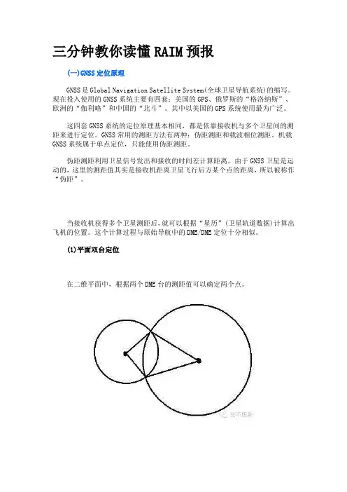
(1)平面双台定位在二维平面中,根据两个DME台的测距值可以确定两个点。
借助诸如VOR径向线等其他定位手段,我们可以将错误的点排除。
FMC可以利用这种方法修正惯性导航系统的误差,得到精确的飞机位置(详见文后说明)。
(2)平面三台定位在平面内如果有三个DME台进行测距,即可得出唯一的位置点。
(3)立体三星定位如果把DME台“装”在卫星上,在三维空间内定位的话,三个测距值能够获得两个位置点。
通过逻辑判断法,系统可以排除错误的位置点,因为错误位置点在太空中,比卫星还高。
这就是三星定位的基本原理。
三颗卫星,三组测距数据,从理论上讲我们已经可以在三维空间中确定飞机的位置了。
(4)时间误差导致的“第四变量”。
GNSS系统利用信号的时间差进行测距。
任何细微的时间误差被放大30万倍(光速)都将变得无法接受。
所以GNSS系统要求卫星和接收机的时间必须保持严格的一致。
GNSS卫星上使用的是原子钟,同时还受地面站的监控和校准。
原子钟精度极高,但是造价高昂。
机载GNSS接收机上使用的是“廉价的”石英钟。

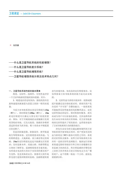
一、卫星导航系统性能的基本要素精度、完好性、连续性、可用性是评价一个卫星导航系统性能的基本要素,其中:1、精度是在给定时间内,接收机给出位置和速度的测量值与真值之间的一致性的度量。
当前卫星导航系统民用定位精度为10m (95%),授时精度为100ns(95%),10m 的定位精度可以满足大部分用户的使用要求。
例如,对于开阔海域的水面舰艇以及商用货轮的导航,以及从航线、航路到非精密进近阶段的飞机导航,数十米的水平精度就已经足够了。
但是在船舶进港、船舶靠岸、狭窄航道航行等特殊场景,定位精度要求到米级;飞机精密进近、大地测量、国土测绘等应用领域,10m的定位精度也远远不能满足应用要求;实时监测水库、高速公路、铁路等附近山体的三维形变,监测精度要求为毫米级;水库或水电站的大坝由于水负荷的重压而产生变形,危及坝体的安全,需要对大坝外观形变进行连续而精密的监测,监测精度则要求为亚毫米级。
如此高的定位精度要求,仅仅单独靠卫星导航系统的能力是无法实现的。
2、完好性是当系统出现异常、故障或精度不能满足设计指标要求时,系统向用户发出实时“不可用”告警的能力,一般用系统不能提供完好性服务的风险概率表示。
没有完好性保证的定位、授时和授时服务,就无法成为用户可以依靠的系统,尤其是那些涉及生命安全相关的应用领域,对卫星导航系统的完好性提出了较高要求,这些要求超出了卫星导航系统自身的服务能力。
涉及生命安全的交通运输领域利用卫星导航系统开展导航应用时,用户更加关注的是当系统处于95%服务可用性之外时,系统的完好性相关服务。
虽然卫星导航系统自身具有一定的完好性监测能力,地面运行控制系统通过接收导航信号和卫星自身健康状态来监测卫星的状态,然后将监测的告警信息上注给卫星并再由卫星以导航电文方式广播给用户,这个周期一般是一个小时,最短也需要15分钟。
卫星导航差分系统和增强系统(一)+刘天雄——什么是卫星导航系统的性能增强?——什么是卫星导航差分系统?——什么是卫星导航增强系统?——卫星导航增强系统分类及技术特点几何?066《卫星与网络》2018年1&2月不同应用领域对卫星导航系统完好性要求不同,例如:①船舶在远洋航路上航行时,对完好性要求相对较低,依靠卫星导航系统提供的完好性保障能力,以及用户接收机内部提供的自主完好性监视,就可满足使用要求;而对于船舶进港与靠岸来说,这个告警时间是不能满足用户需求的,需要建设专门系统在提高定位精度的同时增强卫星导航系统的完好性,保证船舶进港和靠岸的安全。

㊀㊀第52卷㊀第7期测㊀绘㊀学㊀报V o l .52,N o .7㊀2023年7月A c t aG e o d a e t i c ae tC a r t o g r a ph i c aS i n i c a J u l y,2023引文格式:郑帅勇.S B A S 星历星钟增强技术研究[J ].测绘学报,2023,52(7):1231.D O I :10.11947/j.A G C S .2023.20210724.Z H E N GS h u a i y o n g .R e s e a r c ho n t h e t e c h n o l o g i e s o f S B A S c l o c k Ge p h e m e r i s a u g m e n t a t i o n [J ].A c t aG e o d a e t i c a e t C a r t o g r a ph i c a S i n i c a ,2023,52(7):1231.D O I :10.11947/j.A G C S .2023.20210724.S B A S 星历星钟增强技术研究郑帅勇天津理工大学集成电路科学与工程学院,天津300384R e s e a r c h o n t h e t e c h n o l o g i e s o f S B A Sc l o c k Ge p h e m e r i sa u gm e n t a t i o n Z H E N GS h u a i y o n gS c h o o l o f I n t e g r a t e dC i r c u i t S c i e n c ea n dE n g i n e e r i n g ,T i a n j i nU n i v e r s i t y o f T e c h n o l o g y ,T i a n ji n 300384,C h i n a ㊀㊀随着全球卫星导航系统(G l o b a lN a v i ga t i o nS a t e l l i t e S ys t e m ,G N S S )的发展,G N S S 逐渐被应用于航空导航服务.为了满足航空导航性能要求,世界各国致力于G N S S 增强系统尤其是星基增强系统(s a t e l l i t e Gb a s e da u g m e n t a t i o n s ys t e m ,S B A S )的研究,以提升G N S S 的精度㊁完好性㊁连续性和可用性.S B A S 已成为提升G N S S 综合性能尤其是完好性的重要解决措施.美国和欧洲的S B A S 已经能够为航空用户提供垂直引导的定位器性能标准(l o c a l i z e r p e r f o r m a n c e w i t hv e r t i c a l g u i d a n c e200,L P V 200)等级导航服务,S D C M ㊁M S A S ㊁K A S S 和G A G A N 等S B A S 所提供的导航服务信号也逐渐覆盖中国周边地区.而北斗星基增强系统(B D S B A S )还处于建设阶段,迫切需要开展星基增强系统相关研究为B D S B A S 建设和后续性能提升提供技术支持.作为S B A S 系统段的关键技术,星历星钟增强技术关乎B D S B A S 的服务性能,如S B A S 系统段星历星钟增强信息处理效率影响告警时间长短㊁星钟快变误差修正效果影响卫星差分改正数性能㊁星历星钟降效参数准确性将影响服务完好性和连续性㊁刚入境卫星由于收敛时间较长将导致B D S B A S 服务区内可增强卫星数目较少从而服务等级下降.B D S B A S 建设需要攻克这些星历星钟增强技术难题.因此,针对S B A S 星历星钟增强关键技术开展一系列研究,主要包括星钟快变误差修正㊁星历星钟完好性监测㊁星历星钟降效参数求解和连续性性能评估,主要工作内容汇总如下:(1)针对星钟误差修正精度不足的问题,提出了一种基于用户等效测距误差的星钟快速改正数求解算法.该算法根据星钟偏差二阶残余误差特性构造K a l m a n 滤波器状态方程,用经长期改正数修正之后的用户等效测距误差构造K a l m a n 滤波器观测方程.考虑到卫星服务区内低仰角的观测受噪声影响较大,采用环状模型处理多径和接收机热噪声以提升观测质量.利用S a g e 自适应滤波器对系统噪声阵和观测噪声阵进行实时更新,抑制状态方程扰动和观测异常.结果表明:与广域增强系统(w i d e a r e a a u g m e n t a t i o ns ys t e m ,WA A S )算法相比,该算法的星钟误差修正精度明显提升.(2)针对监测网边缘区域星历星钟完好性难以保障的问题,有别于美国WA A S 海外扩展建站的思路,提出了一种基于伪距残差和星站几何的卫星完好监测算法.该算法考虑多误差源㊁星站几何和电文量化与播发对完好性信息的影响,结合卫星运动过程中星站几何变化趋势,对卫星完好性监测进行分段处理,构造了星历星钟协方差阵的凹槽模型,以量化误差最小化的方式处理完好性信息.该算法将星站几何信息引入到卫星完好性监测,改善了监测网边缘区域的卫星完好性,缓解了B D S B A S 短期内无法海外建站的困难.结果表明:该算法相对于直接统计法,伪距域包络率和服务域可用性分别提升24.99%和6.83%,十分接近WA A S 相应指标.(3)针对用户错过部分增强电文时S B A S 完好性降低的问题,提出了一种基于舍入误差和外推误差的星历星钟降效参数求解算法.该算法在分析S B A S 电文参数的估计模糊度㊁高阶误差㊁舍入误差以及外推误差之后,对这些误差采用相应的概率分布进行描述,给出S B A S 电文参数超出有效时间间隔后引起的残余误差.通过求解残余误差的上确界来推导相应降效参数.该算法首次公开介绍了星历星钟降效参数求解方法,为B D S B A S 降效参数求解提供了理论依据.结果表明:该算法降效参数估计值与WA A S 相应参数十分接近.(4)针对稀疏样本难以准确评估系统连续性的问题,提出了一种基于W e i b u l l 分布的可调参数的连续性评估算法.该算法对G N S S 中断数据进行最大似然估计拟合处理以确定W e i b u l l 分布参数估计值,将均方误差最小的一组参数估计值作为W e i b u l l 分布最终参数估计结果并求取G N S S 连续性.该算法可以根据中断数据来灵活确定系统故障率,为B D S B A S 性能测试评估提供了一种技术途径.结果表明:该算法性能较传统算法提升40.42%,更加接近官方报告结果.在完成如上算法的设计与验证后,利用WA A S 数据进行性能分析以评估所提算法的整体性能.结果表明:与WA A S 算法相比,所提算法空间信号改正精度明显提升,伪距域包络率降低0.06%,L P V 200可用性降低2.10%,与国外已有系统达到同等水平.然后,将所提算法应用于中国区域,以评估所提算法的先进性并预报中国区域S B A S 性能.结果表明:与直接统计法相比,所提算法空间信号改正精度接近,伪距域包络率提升45.39%,L P V 200可用性提升2.32%,性能优于直接统计法.所提算法可以为中国大部分地区提供类一类垂直引导的进近程序(a p p r o a c h p r o c e d u r ew i t h v e r t i c a l gu i d a n c e GI ,A P V GI )等级服务甚至部分地区提供L P V 200等级服务.相关内容及成果已作为关键技术应用于北斗星基增强系统民用服务平台的监测站和信息处理中心.中图分类号:T N 967.1㊀㊀㊀㊀文献标识码:D文章编号:1001G1595(2023)07G1231G01基金项目:复杂电子系统仿真重点实验室开放基金(614201004012103);卫星导航系统与装备技术国家重点实验室开放基金(C E P N T 2022B 03);自然资源部国土卫星遥感应用重点实验室开放基金(K L S MN R G202310)收稿日期:2021G12G28作者简介:郑帅勇(1991 ),男,2021年毕业于北京航空航天大学,获工学博士学位(指导教师:黄智刚教授,李锐高级工程师),研究方向为卫星导航.A u t h o r :Z H E N G S h u a i y o n g (1991 ),m a l e ,r e c e i v e d h i sd o c t o r a ld e g r e ef r o m B e i h a n g U n i v e r s i t y i n 2021,m a j o r s i ns a t e l l i t en a v i ga t i o n .E Gm a i l :s y z h e n g 21@e m a i l .t ju t .e d u .c n Copyright ©博看网. All Rights Reserved.。
北斗导航系统跨系统联合定位与授时技术解析北斗导航系统实现跨系统联合定位和授时,主要依赖于其强大的技术实力和广泛的国际合作,具体实现方式如下:一、信号设计与兼容1.频段共用与信号体制:o北斗系统在设计信号时,充分考虑了与其他全球卫星导航系统的兼容性。
例如,北斗B1I信号与GPS L1 C/A信号共用1575.42MHz频点,这种设计使得用户设备能够同时接收和处理来自北斗和其他系统的信号,为跨系统联合定位提供了可能。
o北斗还尽量采用与其他系统相似的调制方式、带宽等频域参数,以确保高度的互操作性。
这种设计简化了接收机的结构,提高了接收机的兼容性和效率。
2.时间同步与标准:o北斗导航系统支持国际通用的时间标准,如UTC(协调世界时)。
通过与国家授时中心(NTSC)等权威机构的合作,北斗确保了系统时间的准确性和稳定性。
o北斗还采用先进的时间同步协议(如NTP、PTP等),确保卫星、地面控制系统和用户终端之间的时间一致性,为跨系统授时提供了有力保障。
二、系统增强服务1.地基增强系统(GBAS):o北斗建立了完善的地基增强系统,通过地面站网播发差分改正信息,提高定位精度。
这些差分改正信息不仅适用于北斗系统内部,还可以与其他系统的地基增强服务实现互联互通,进一步提升跨系统联合定位的精度和可靠性。
2.卫星增强服务(SBAS):o北斗还提供了基于卫星的增强服务,如区域短报文通信服务(RDSS)。
虽然这主要是一种通信服务,但它也为跨系统联合定位提供了额外的信息支持。
此外,随着技术的不断发展,北斗可能会推出更多针对定位精度提升的卫星增强服务。
三、国际合作与互操作1.兼容与互操作协议:o北斗系统积极参与国际卫星导航领域的合作与交流,与GPS、GLONASS、Galileo等系统签署了多项兼容与互操作协议。
这些协议明确了双方在信号设计、频段使用、时间同步等方面的兼容与互操作要求,为跨系统联合定位和授时提供了制度保障。
2.技术交流与合作:o北斗系统与其他全球卫星导航系统建立了技术交流和合作机制,通过共享技术成果、开展联合测试和应用推广等方式,不断提升跨系统联合定位和授时的性能和可靠性。
Number:CTSO-C145eApproved by:Xu ChaoqunChina Civil Aviation Technical Standard OrderAirborne Navigation Sensors Using The Global Positioning SystemAugmented By The Satellite Based Augmentation System (SBAS)1. Purpose.This China Civil Aviation Technical Standard Order (CTSO) is for manufacturers applying for airborne navigation sensors using the global positioning system (GPS) augmented by the satellite based augmentation system (SBAS) CTSO authorization (CTSOA). This CTSO prescribes the minimum performance standards(MPS) that airborne navigation sensors using the GPS augmented by the SBAS must first meet for approval and identification with the applicable CTSO marking.2. Applicability.This CTSO affects new application submitted after its effective date.Major design changes to article approved under this CTSO will require a new authorization in accordance with section 21.353 of CCAR-21R4.3. RequirementsNew models of airborne navigation sensors using the GPS augmented by the SBAS identified and manufactured on or after the effective date of this CTSO must meet the MPS qualification and documentation requirements for functional equipment Class Beta in RTCA, Inc. document RTCA/DO-229E, Minimum Operational Performance Standards for Global Positioning System/Satellite-Based Augmentation System Airborne Equipment dated December 15, 2016, Section 2.1. Class Beta equipment is defined in RTCA/DO-229E, Section 1.4 and Appendix 2 adds a new section 1.8.3.Note: Manufacturers have the option to use the RTCA/DO-229E change described in Appendix 3. The change is based on a past commonly granted deviation.a. An alternate method for applicants is to apply for CTSO-C145e using their existing approved design data plus additional substantiation data showing compliance with the changes in RTCA/DO-229E. The three areas where requirements changed are: 1) expanding the SBAS pseudorandom noise (PRN) codes (i.e., PRN range of 120 thru 158); 2) ensuring a graceful degradation to GPS-only operations; and, 3) prohibiting use of the broadcast Navigation Message Correction Table.Note 1: It is not necessary for applicants to re-submit previously approved deviations. Previously approved deviations, and any limitations,will apply to the CTSO-C145e CTSOA.Note 2: Applicants with Class 1 and 2, revision ‘b’ equipment must not have claimed the 3db broadband intrasystem noise credit.b. CTSO-C145e applicants have the option to use a CTSO-C204a SBAS CCA functional sensor. Applicants choosing to use a CTSO-C204a SBAS CCA can take certification compliance credit by virtue of the CTSO-C204a CTSOA for:z Meeting the MPS section 2.1 requirements;z The hardware/software qualification;z The failure condition classification; and,z MPS section 2.5 performance testing (functional qualification) except those specified in Appendix 1 of this CTSO.c. The CTSO-C145e applicant using a CTSO-C204a SBAS CCA functional sensor shall perform the testing described in Appendix 1 and satisfy the remaining paragraphs in this CTSO not covered by the bullets above to receive a CTSO-C145e CTSOA.Note: The end-use manufacturer using a CTSO-C204a SBAS CCA functional sensor as part of their CTSO-C145e application assumes full responsibility for the design and function under their CTSO-C145e authorization.d. Functionality.This CTSO’s standards apply to equipment intended to provideposition, velocity, time information for a navigation management unit application that outputs deviation commands keyed to a desired flight path, or a non-navigation application such as automatic dependent surveillance-broadcast (ADS-B) or terrain awareness and warning system (TAWS). In navigation applications, pilots or autopilots will use the deviations output by the navigation management unit to guide the aircraft. In non-navigation applications, the position, velocity, time outputs will provide the necessary input for the end-use equipment. These TSO standards do not address integration issues with other avionics.e. Failure Condition Classifications.(1) Failure of the function defined in paragraph 3.d resulting in misleading information for en route, terminal, approach lateral navigation (LNA V), and approach LNA V/vertical navigation (VNA V) position data is a Major failure condition.(2) Failure of the function defined in paragraph 3.d resulting in misleading information for approach localizer performance without vertical guidance (LP), and approach localizer performance with vertical guidance (LPV) position data is a Hazardous failure condition.(3) Loss of the function defined in paragraph 3.d for enroute through approach LP/LPV position data is a Major failure condition.(4) Design the system to at least these failure condition classifications.f. Functional Qualification.(1) Demonstrate the required functional performance under the test conditions specified in RTCA/DO-229E, Section 2.5, or(2) When using a CTSO-C204a SBAS CCA functional sensor, demonstrate the required performance under the test conditions in appendix 1 of this CTSO.g. Environmental Qualification.Demonstrate the required performance under the test conditions specified in RTCA/DO-229E, Section 2.4 using standard environmental conditions and test procedures appropriate for airborne equipment. RTCA/DO-229E requires the use of RTCA/DO-160E, Environmental Conditions and Test Procedures for Airborne Equipment, dated December 9, 2004, Sections 4.0 through 8.0 and 10.0 through 25.0. You may use a different standard environmental condition and test procedure than RTCA/DO-160E, provided the standard is appropriate for the SBAS sensor.Note1: The use of RTCA/DO-160D (with Changes 1 and 2 only, incorporated) or earlier versions is generally not considered appropriate and will require substantiation via the deviation process as discussed in paragraph 3.k of this CTSO.Note 2: Applicants using a CTSO-C204a SBAS CCA sensor must perform the environmental qualification with the SBAS CCA in theend-use equipment.h. Software Qualification.If the article includes software, develop the software according to RTCA/DO-178C, Software Considerations in Airborne Systems and Equipment Certification, dated December 13, 2011, including referenced supplements as applicable, to at least the software level consistent with the failure condition classification defined in paragraph 3.e of this CTSO. The applicant may also develop the software according to RTCA/DO-178B, dated December 1, 1992.(2) Applicants using a CTSO-C204a SBAS CCA sensor may use CTSO-C204a as substantiation for the software qualification.i. Electronic Hardware Qualification.If the article includes complex custom airborne electronic hardware, develop the component according to RTCA/DO-254, dated April 19, 2000, Design Assurance Guidance for Airborne Electronic Hardware, to at least the design assurance level consistent with the failure condition classification defined in paragraph 3.e of this CTSO. For custom airborne electronic hardware determined to be simple, RTCA/DO-254, paragraph1.6 applies.(2) Applicants using a CTSO-C204a SBAS CCA sensor may use CTSO-C204a as substantiation for the hardware qualification.j. Barometric-aided Fault Detection and Exclusion (FDE).If the equipment uses barometric-aiding to enhance FDE availability, then the equipment must meet the requirements in RTCA/DO-229E, appendix G.k. Deviations.For using alternative or equivalent means of compliance to the criteria in this CTSO, the applicant must show that the equipment maintains an equivalent level of safety. Apply for a deviation under the provision of 21.368(a) in CCAR-21R4.4. Marking.a. Mark at least one major component permanently and legibly with all the information in 21.423(b) of CCAR-21R4. The marking must include the serial number.b. Also, mark the following permanently and legibly, with at least the manufacturer’s name, subassembly part number, and the CTSO number:(1) Each component that is easily removable (without hand tools); and,(2) Each subassembly of the article that manufacturer determined may be interchangeable.c. If the article includes software and/or airborne electronic hardware, then the article part numbering scheme must identify the software andairborne electronic hardware configuration. The part numbering scheme can use separate, unique part numbers for software, hardware, and airborne electronic hardware.d. The applicant may use electronic part marking to identify software or airborne electronic hardware components by embedding the identification within the hardware component itself (using software) rather than marking it on the equipment nameplate. If electronic marking is used, it must be readily accessible without the use of special tools or equipment.e. At least one major component must be permanently and legibly marked with the operational equipment class (for example, Class 2) as defined in RTCA/DO-229E, Section 1.4.2.5. Application Data Requirements.The applicant must furnish the responsible certification personnel with the related data to support design and production approval. The application data include a statement of conformance as specified in section 21.353(a)(1) in CCAR-21R4 and one copy each of the following technical data:a. A Manual(s) containing the following:(1) Operating instructions and equipment limitations sufficient to describe the equipment’s operational capability.(2) Describe in detail any deviations.(3) Installation procedures and limitations sufficient to ensure that the SBAS sensor, when installed according to the installation or operational procedures, still meets this CTSO’s requirements. Limitations must identify any unique aspects of the installation. The limitations must include a note with the following statement:“This article meets the minimum performance and quality control standards required by a CTSO. Installation of this article requires separate approval.”(4) For each unique configuration of software and airborne electronic hardware, reference the following:(a) Software part number including revision and design assurance level;(b) Airborne electronic hardware part number including revision and design assurance level;(c) Functional description.(5) A summary of the test conditions used for environmental qualifications for each component of the article. For example, a form as described in RTCA/DO-160G, Environmental Conditions and Test Procedures for Airborne Equipment, Appendix A.(6) Schematic drawings, wiring diagrams, and any other documentation necessary for installation of the SBAS sensor.(7) List of replaceable components, by part number, that makes up the SBAS sensor. Include vendor part number cross-references, when applicable.(a) If the equipment can satisfy the requirements of RTCA/DO-229E only when used with a particular antenna, make the use of that antenna (by part number) a requirement on the installation. Include this requirement in the installation manual (IM) as a limitation.(b) If the equipment is installed with a standard antenna, include maximum tolerable currents and voltages into the antenna port. See CTSO-C144a, Passive Airborne Global Navigation Satellite System (GNSS) Antenna, applicable only to operational Class 1 equipment, or CTSO-C190, Active Airborne Global Navigation Satellite System (GNSS) Antenna, applicable to all equipment operational classes.b. Instructions covering periodic maintenance, calibration, and repair, for the continued airworthiness of the SBAS sensor. Include recommended inspection intervals and service life, as appropriate.c. If not using a CTSO-C204a SBAS functional sensor and the article includes software: a plan for software aspects of certification (PSAC), software configuration index, and software accomplishment summary.d. If not using a CTSO-C204a SBAS functional sensor and the article includes simple or complex custom airborne electronic hardware: aplan for hardware aspects of certification (PHAC), hardware verification plan, top-level drawing, and hardware accomplishment summary (or similar document, as applicable).e. A drawing depicting how the article will be marked with the information required by paragraph 4 of this CTSO.f. Adequate specifics on the interface between the SBAS sensor and other systems to ensure proper functioning of the integrated system. If the equipment depends on any external inputs (like baro-aided FDE) to satisfy the requirements of RTCA/DO-229E, make those inputs a requirement in the installation. Include this requirement in the IM as a limitation.g. If the software qualification limits eligibility of the equipment to certain aircraft types, identify the qualification level, and that the equipment is not eligible for all aircraft types. For example, RTCA/DO-178B (or RTCA/DO-178C) Level C software may be associated with a hazardous failure condition for certain aircraft types. Identify other limitations applicable to the failure condition classification, for example, that two installed units are necessary.h. If the equipment has not been demonstrated as compatible with satellite communications (SatCom) record in the limitations section that the equipment should not be installed in SatCom equipped aircraft.i. Identify functionality or performance contained in the article notevaluated under paragraph 3 of this CTSO (that is, non-CTSO functions). Non-CTSO functions are accepted in parallel with the CTSO authorization. For those non-CTSO functions to be accepted, you must declare these functions and include the following information with your CTSO application:(1) Description of the non-CTSO function(s), such as performance specifications, failure condition classifications, software, hardware, and environmental qualification levels. Include a statement confirming that the non-CTSO function(s) do not interfere with the article’s compliance with the requirements of paragraph 3.(2) Installation procedures and limitations sufficient to ensure that the non-CTSO function(s) meets the declared functions and performance specification(s) described in paragraph 5.i.(1).(3) Instructions for continued performance applicable to the non-CTSO function(s) described in paragraph 5.i.(1).(4) Interface requirements and applicable installation test procedures to ensure compliance with the performance data defined in paragraph 5.i.(1).(5) Test plans, analysis and results, as appropriate, to verify that performance of the hosting CTSO article is not affected by the non-CTSO function(s).(6) Test plans, analysis and results, as appropriate, to verify thefunction and performance of the non-CTSO function(s) as described in paragraph 5.i.(1).(7) Alternatively, identify non-CTSO functionality or performance contained in the article not evaluated under paragraph 3 and submit previously accepted data for the non-CTSO function for acceptance in parallel with this CTSO application.j. The quality system description required by section 21.358 of CCAR-21R4, including functional test specifications. The quality system should ensure that it will detect any change to the approved design that could adversely affect compliance with the CTSO MPS, and reject the article accordingly.k. Material and process specifications list.l. List of all drawings and processes (including revision level) that define the article’s design.m. Manufacturer’s CTSO qualification report showing results of testing accomplished according to paragraph 3.f of this CTSO.6. Manufacturer Data Requirements.Besides the data given directly to the authorities, have the following technical data available for review by the authorities:a. Functional qualification specifications for qualifying each production article to ensure compliance with this CTSO.b. Equipment calibration procedures.c. Schematic drawings.d. Wiring diagrams.e. Material and process specifications.f. The results of the environmental qualification tests conducted according to paragraph 3.g of this CTSO.g. If the article includes software, the appropriate documentation defined in the version of RTCA/DO-178 or RTCA/DO-178C specified by paragraph 3.h of this CTSO, including all data supporting the applicable objectives in Annex A, Process Objectives and Outputs by Software Level.h. If the article includes complex custom airborne electronic hardware, the appropriate hardware life cycle data in combination with design assurance level, as defined in RTCA/DO-254, Appendix A, Table A-l. For simple custom airborne electronic hardware, the following data: test cases or procedures, test results, test coverage analysis, tool assessment and qualification data, and configuration management records, including problem reports.i. If not using CTSO-C204a, all the data necessary to evaluate the geo stationary (GEO) satellite bias as defined in RTCA/DO-229E, Section 2.1.4.1.5.j. If the article contains non-CTSO function(s), the applicant mustalso make available items 6.a through 6.h as they pertain to the non-CTSO function(s).7. Furnished Data Requirements.a. If furnishing one or more articles manufactured under this CTSO to one entity (such as an operator or repair station), provide one copy or technical data and information specified in paragraphs 5.a and 5.b of this CTSO. Add any data needed for the proper installation, certification, use, or for continued compliance with the CTSO, of the SBAS sensor.b. If the article contains declared non-CTSO function(s), include one copy of the data in paragraphs 5.i.(1) through 5.i.(4).8. Availability of Referenced Documents.Order RTCA documents from:Radio Technical Commission for Aeronautics, Inc.1150 18th Street NW, Suite 910, Washington D.C. 20036You may also order them online from the RTCA Internet website at: .APPENDIX 1. END-USE EQUIPMENT MANUFACTURER TESTS FOR SBAS CCA FUNCTIONAL POSITION, VELOCITY, TIME (PVT) SENSORS USED FOR NA VIGATION AND NON-NA VIGATION APPLICATIONS1. Scope.This appendix describes the required supplementary equipment level testing, in addition to the environmental testing of RTCA/DO-229E, section 2.4, required by the end-use equipment manufacturer to receive a CTSO-C145e Class Beta authorization when using a CTSO-C204a SBAS CCA functional sensor. These test procedures are intended to streamline and simplify the CTSO-C145e authorization process for the end-use equipment manufacturer by allowing credit for the design and selected testing done at the SBAS CCA functional sensor level. However, the end-use equipment manufacturer retains full responsibility for the design and control of the article per their CTSO-C145e CTSOA.2. General Principles.(a) Testing methods for GPS/SBAS equipment have been standardized by RTCA/DO-229E and serve as the basis for CTSO-C145e. RTCA/DO-229E was written with the perspective of equipment that canbe installed on aircraft. Section 2.4 specifically addresses the issues of the environment in which the equipment operates and provides approved test methods to validate performance in this environment. Section 2.4represents RTCA consensus in identifying which RTCA/DO-229E requirements are sensitive to environmental effects. These requirements are listed in the environmental tables referenced in section 2.4.1.(b) The determination that a MOPS requirement is susceptible to the environment does not depend on whether or not the implementation is a CCA within some host equipment. This is the same concept as an equipment enclosure designed to protect against a benign environment compared to one designed for a severe environment; the identification of susceptible requirements is the same.(c) Therefore this appendix uses the tables of RTCA/DO-229E, section 2.4.1 to identify the MOPS requirements susceptible to environmental affects for an SBAS CCA functional sensor in the end-use equipment. The focus is on the change in environment seen by the SBAS CCA functional sensor as a result of its installation in the end-use equipment. For example, other components inside the end-use equipment may radiate RF energy that could interfere with the GPS functions; therefore the ambient testing done at CCA level is not equivalent to tests done in the end-use equipment. This is the basis for defining the RTCA/DO-229E, section 2.5 performance tests that need to be repeated by the end-use equipment manufacturer.(d) The Class Beta environmental table referenced in RTCA/DO-229E, section 2.4.1 are the prime source to determine theMOPS performance requirements susceptible to environmental conditions. Based on the table, the susceptible requirements can be grouped in two categories: those susceptible to most types of environmental conditions (described in section 3) and those susceptible to just a few (described in section 4).Note: The Tables for Class Beta-1, -2, and -3 equipment identify similar requirements susceptible to the installed environment. The only difference is the applicable MOPS requirements consistent with the operational class (i.e., class -1, - 2, or -3).3. Performance Requirements Susceptible to Most Environmental Conditions.The RTCA/DO-229E requirements for Accuracy (2.1.3.1, 2.1.4.1, and 2.1.5.1) and Sensitivity and Dynamic Range (2.1.1.10) are sensitive to most environmental conditions. However, these requirements are linked to the message loss rate requirement in 2.1.1.3.2. Section 3.1 and 3.2 below identifies the testing end-use equipment manufacturers are required to repeat to demonstrate the SBAS CCA functional sensor continues to meet the Accuracy, Dynamic Range, and Message Loss Rate performance requirements after installation in the end-use equipment. All tests will be run under conditions where the end-use equipment functions are fully enabled to create the worst-case environment.3.1 RTCA/DO-229E, 2.5.8 Accuracy Test.(a) The accuracy test described in section 2.5.8 is actually a joint test covering both accuracy, and sensitivity and dynamic range. This joint testing also applies under environment as stated in section 2.4.1.1.5 with environmental adaptation as described in section 2.4.1.1.1.(b) The demonstration of accuracy is done in accordance with section 2.5.8.1 only for the test case with a broadband external interference noise. This test must be repeated when the CCA is installed in the end-use equipment and it is sufficient to perform it using broadband interference.(1) The environmental testing is limited to broadband interference as it represents the worst case signal to noise condition which is the most sensitive to environmental effects. This applies equally to the environment for the CCA created by the end-use equipment.(2) Section 2.5.8 contains a measurement accuracy test in 2.5.8.1 with the detailed test procedure in 2.5.8.2. The 2.5.8.1 test must be run under the worst case environment identified in the “Additional considerations for internal interference sources” section below. The measurement accuracy testing can be combined with the message loss rate testing in 2.5.2.1.(3) Section 2.5.8.3 is a 24-Hour actual satellite accuracy test. The section 2.5.8.3 test exposes the equipment to a variety of signal conditions and data processing conditions over varying satellite geometrythat will increase confidence that no unforeseen interactions between components within the end-use equipment and the SBAS CCA functional sensor goes undetected. The 24 hr testing in 2.5.8.3 can be combined with the 24 hr message loss rate testing in 2.5.2.4 (see Additional Considerations for Internal Interference Sources section).(4) Section 2.5.8.4 (SBAS Tracking Bias) is an analysis of the GPS hardware and is therefore not necessary to repeat at the end-use equipment level as long as no extra RF components that affect the RF filtering response are inserted in the RF path. Otherwise the end-use equipment manufacturer must repeat the SBAS Tracking Bias test as well.(c) The test threshold is relaxed from 110% to 125% as specified in table 2-25 of the 2.5.8.2.1 test procedure to shorten test time. However, Section 2.5.8 testing (excluding the SBAS Tracking Bias test in 2.5.8.4) for the CCA in the end-use equipment shall be under ambient conditions per section 2.5 with the 110% test pass threshold for maximum test sensitivity.(d) The Section 2.5.8 testing (excluding the SBAS Tracking Bias test in 2.5.8.4) will be repeated against the accuracy requirement consistent with the desired operational class (i.e., 2.1.3.1, 2.1.4.1, and 2.1.5.1 accuracy requirements as appropriate).(e) Only the broadband external interference noise test case usingminimum satellite power will be executed in most cases to shorten test time. Section 2.5.8.1 testing will be repeated for both minimum and maximum satellite power for the worst case environment only.3.2 RTCA/DO-229E, 2.5.2 Message Loss Rate Test.(a) Section 2.5.2 specifies the message loss rate test for the 2.1.1.3.2 message loss rate requirement. This test is conducted in conjunction with the 2.5.8 accuracy testing. Section 2.5.2.2 defines the test procedure to collect data verifying the SBAS message loss rate in the presence of interference using the test cases where the SBAS satellite is at minimum power. Section 2.5.2.3 defines the pass/fail criteria.(b) The test in section 2.5.2.2 will be performed during the measurement accuracy broadband interference test case described in paragraph 3.1.(c) The test procedure in section 2.5.2.4.1 is run in conjunction with the 2.5.8.3 24-hour accuracy test. Section 2.5.2.4.2 defines the pass/fail criteria for the test case described in paragraph 3.1(b)(3).4. Performance Requirements Partially Susceptible to Environmental Conditions.(a) The class Beta tables (tables 2-14, 2-16, and 2-18) in section2.4.1 of RTCA/DO-229E indicates the requirements for Initial Acquisition Time (2.1.1.7) and Satellite Reacquisition Time (2.1.1.9) are sensitive to four environmental conditions: Icing, Lightning InducedTransient Susceptibility, Lightning Direct Effects, and Normal/Abnormal Operating Conditions. The requirements for Loss of Navigation (2.1.1.13.2, 2.1.4.12.2, and 2.1.5.12.2) and Loss of Integrity (2.1.1.13.1, 2.1.4.12.1, and 2.1.5.12.1) are sensitive to low and high operating temperature.(b) The Lightning Induced Transient Susceptibility, Lightning Direct Effects, or Icing environmental conditions are not pertinent to the environment created by the end-use equipment relative to the SBAS CCA functional sensor. However, the end-use equipment manufacturer remains responsible for meeting the overall environmental qualification at the end-use equipment level.(c) Loss of navigation and loss of integrity indications are limited to temperature testing and the information in RTCA/DO-229E, sections 2.4.1.1.2 and 2.4.1.1.3 is appropriate. The purpose is to ensure that the interface used to indicate the loss of navigation is functional under environmental conditions after the SBAS CCA functional sensor is installed in the end-use equipment. Sections 2.4.1.1.2 and 2.4.1.1.3 indicate that any source that generates the indication can be used since it is the interface and not the detection mechanism that is verified. The temperature testing done at the end-use equipment level is the worst-case scenario. It is not necessary to repeat the CCA level test at room temperature in the end-use equipment since the environmentalqualification adequately addresses testing for these requirements.(d) RTCA/DO-160E section 16 relates to aircraft power supply (refer to TSO paragraph 3.g for environmental qualification requirements). Sections 16.5.1.2 and 16.6.1.2 are for supply voltage modulation (ac) /ripple (dc). Given the potential susceptibility of the SBAS CCA functional sensor to power supply noise, it is prudent to repeat tests at the end-use equipment level on this basis.(e) Sections 4.1 and 4.2 identify the testing end-use equipment manufacturers are required to repeat to demonstrate the SBAS CCA functional sensor continues to meet the Acquisition Time and Reacquisition Time performance requirements relative to Normal/Abnormal Operating Conditions after installation in the end-use equipment. All tests will be run under conditions where the end-use equipment functions are fully enabled to create the worst-case environment.4.1 2.5.4 Initial Acquisition Test Procedures.The information in RTCA/DO-229E, section 2.4.1.1.4 on the initial acquisition test in section 2.5.4 applies. The end-use equipment manufacturer shall repeat the initial acquisition testing described in RTCA/DO-229E, section 2.5.4.4.2 2.5.6 Satellite Reacquisition Time Test.The end-use equipment manufacturer is required to repeat the。