
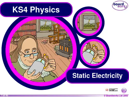
KS4 Electricity - Static Electricity
- 格式:pptx
- 大小:3.81 MB
- 文档页数:79

GETTING STARTED GUIDENI PXIe-7846RR Series Reconfigurable I/O Module (AI, AO, DIO) for PXI Express,8 AI, 8 AO, 48 DIO, 500 kS/s AI, Kintex-7 160T FPGAThis document describes how to begin using the NI PXIe-7846R.Safety GuidelinesCaution Do not operate the NI PXIe-7846R in a manner not specified in thisdocument. Product misuse can result in a hazard. You can compromise the safetyprotection built into the product if the product is damaged in any way. If the productis damaged, return it to NI for repair.Electromagnetic Compatibility GuidelinesThis product was tested and complies with the regulatory requirements and limits for electromagnetic compatibility (EMC) stated in the product specifications. These requirements and limits provide reasonable protection against harmful interference when the product is operated in the intended operational electromagnetic environment.This product is intended for use in industrial locations. However, harmful interference may occur in some installations, when the product is connected to a peripheral device or test object, or if the product is used in residential or commercial areas. To minimize interference with radio and television reception and prevent unacceptable performance degradation, install and use this product in strict accordance with the instructions in the product documentation.Furthermore, any changes or modifications to the product not expressly approved by National Instruments could void your authority to operate it under your local regulatory rules.Caution To ensure the specified EMC performance, operate this product only withshielded cables and accessories.Caution To ensure the specified EMC performance, the length of all I/O cablesmust be no longer than 3 m (10 ft).Preparing the EnvironmentEnsure that the environment in which you are using the NI PXIe-7846R meets the following specifications.0 °C to 55 °COperating temperature(IEC 60068-2-1, IEC 60068-2-2)Operating humidity (IEC 60068-2-56)10% RH to 90% RH, noncondensing Pollution degree2Maximum altitude2,000 mIndoor use only.Note Refer to the device specifications on /manuals for completespecifications.Unpacking the KitCaution To prevent electrostatic discharge (ESD) from damaging the device,ground yourself using a grounding strap or by holding a grounded object, such asyour computer chassis.1.Touch the antistatic package to a metal part of the computer chassis.2.Remove the device from the package and inspect the device for loose components or anyother sign of damage.Caution Never touch the exposed pins of connectors.Note Do not install a device if it appears damaged in any way.2| | NI PXIe-7846R Getting Started Guide3.Unpack any other items and documentation from the kit.Store the device in the antistatic package when the device is not in use.Verifying the Kit ContentsVerify that the following items are included in the NI PXIe-7846R kit.Figure 1. NI PXIe-7846R Kit Contents1.Hardware2.NI-RIO Media3.Getting Started GuideInstalling Software on the Host ComputerBefore using the NI PXIe-7846R, you must install the following application software and device drivers on the host computer.bVIEW 2016 or laterbVIEW Real-Time Module 2016 or later1bVIEW FPGA Module 2016 or later4.NI R Series Multifunction RIO Device Drivers August 2016 or laterVisit /info and enter the Info Code softwareversion for minimum software support information.Installing the NI PXIe-7846RCaution To prevent damage to the device caused by ESD or contamination, handlethe device using the edges or the metal bracket.1.Ensure the AC power source is connected to the chassis before installing the modules.The AC power cord grounds the chassis and protects it from electrical damage while you install the modules.1LabVIEW Real Time Module is only required when the R Series board is used in a chassis where the PXIe Controller is running a real-time operating system.NI PXIe-7846R Getting Started Guide | © National Instruments| 33.Inspect the slot pins on the chassis backplane for any bends or damage prior to installation. Do not install a module if the backplane is damaged.4.Remove the black plastic covers from all the captive screws on the module front panel.5.Identify a supported slot in the chassis. The following figure shows the symbols that indicate the slot types.Figure 2. Chassis Compatibility Symbols1.PXI Express System Controller Slot2.PXI Peripheral Slot3.PXI Express Hybrid Peripheral Slot4.PXI Express System Timing Slot5.PXI Express Peripheral SlotNI PXIe-7846R modules can be placed in PXI Express peripheral slots, PXI Express hybrid peripheral slots, or PXI Express system timing slots.6.Touch any metal part of the chassis to discharge static electricity.7.Place the module edges into the module guides at the top and bottom of the chassis. Slide the device into the slot until it is fully inserted.Figure 3. Module Installation1.Chassis2.System Controller3.Hardware Module4.Front-Panel Mounting Screws5.Module Guides6.Power Switch8.Secure the device front panel to the chassis using the front-panel mounting screws.Note Tightening the top and bottom mounting screws increases mechanicalstability and also electrically connects the front panel to the chassis, which can improve the signal quality and electromagnetic performance.9.Cover all empty slots with filler panels or use slot blockers to maximize cooling air flow.4 | | NI PXIe-7846R Getting Started GuideVerifying Hardware Installation for Host Targets You can verify that the system recognizes the NI PXIe-7846R by using Measurement & Automation Explorer (MAX).unch MAX by navigating to Start»All Programs»National Instruments»MAX or byclicking the MAX desktop icon.2.Expand Devices and Interfaces.3.Verify that the device appears under Devices and Interfaces.If the device does not appear, press <F5> to refresh the view in MAX. If the device does not appear after refreshing the view, visit /support for troubleshooting information. Verifying Hardware Installation for Remote TargetsYou can verify that the system recognizes the NI PXIe-7846R by using Measurement & Automation Explorer (MAX).unch MAX on the host computer.2.Expand Remote Targets in the configuration tree and locate your system.3.Install LabVIEW Real-Time Module 2016 and NI RIO Device Drivers August 2016 orlater on your Remote Target.a)Refer to the Installing Software on the Host Computer section for information aboutinstalling software on the host.b)Refer to the PXI Express Controllers User Manual at /manuals forinformation on installing software on the target.4.Under Remote Targets, find and expand Devices and Interfaces.If the device does not appear, press <F5> to refresh the view in MAX. If the device does not appear after refreshing the view, visit /support for troubleshooting information.NI PXIe-7846R Getting Started Guide | © National Instruments| 5PinoutCONNECTOR 1(DIO)CONNECTOR 0(MIO)Table 1. NI PXIe-7846R Signal Descriptions6 | | NI PXIe-7846R Getting Started GuideTable 1. NI PXIe-7846R Signal Descriptions (Continued)The NI PXIe-7846R is protected from overvoltage and overcurrent conditions.Note Refer to the device specifications, available at /manuals for moreinformation.NI PXIe-7846R Getting Started Guide | © National Instruments| 7Where to Go NextWorldwide Support and ServicesThe NI website is your complete resource for technical support. At /support, you have access to everything from troubleshooting and application development self-help resources to email and phone assistance from NI Application Engineers.Visit /services for NI Factory Installation Services, repairs, extended warranty, and other services.Visit /register to register your NI product. Product registration facilitates technical support and ensures that you receive important information updates from NI.A Declaration of Conformity (DoC) is our claim of compliance with the Council of the European Communities using the manufacturer’s declaration of conformity. This system affords the user protection for electromagnetic compatibility (EMC) and product safety. You can obtain the DoC for your product by visiting /certification. If your product supports calibration, you can obtain the calibration certificate for your product at /calibration. 8| | NI PXIe-7846R Getting Started GuideNI corporate headquarters is located at 11500 North Mopac Expressway, Austin, Texas, 78759-3504. NI also has offices located around the world. For telephone support in the United States, create your service request at /support or dial 1 866 ASK MYNI (275 6964). For telephone support outside the United States, visit the Worldwide Offices section of / niglobal to access the branch office websites, which provide up-to-date contact information, support phone numbers, email addresses, and current events.NI PXIe-7846R Getting Started Guide | © National Instruments| 9Refer to the NI Trademarks and Logo Guidelines at /trademarks for information on NI trademarks. Other product and company names mentioned herein are trademarks or trade names of their respective companies. For patents covering NI products/technology, refer to the appropriate location: Help»Patents in your software, the patents.txt file on your media, or the National Instruments Patent Notice at /patents. Y ou can find information about end-user license agreements (EULAs) and third-party legal notices in the readme file for your NI product. Refer to the Export Compliance Information at /legal/export-compliance for the NI global trade compliance policy and how to obtain relevant HTS codes, ECCNs, and other import/export data. NI MAKES NO EXPRESS OR IMPLIED WARRANTIES AS TO THE ACCURACY OF THE INFORMA TION CONTAINED HEREIN AND SHALL NOT BE LIABLE FOR ANY ERRORS. U.S. Government Customers: The data contained in this manual was developed at private expense and is subject to the applicable limited rights and restricted data rights as set forth in FAR 52.227-14, DFAR 252.227-7014, and DFAR 252.227-7015.© 2016 National Instruments. All rights reserved.375944B-01May16。

k的值静电常量
静电力常数k是在计算电场力大小时一个已被测定的额定常数,又叫静电力常量,数值为k=9.0×10⁹ N·m2/C2 ,它表示真空中两个相距为1m、电荷量都为1C的点电荷之间的相互作用力为9.0×10⁹ N.
电场是电荷周围空间存在的一种物质,其基本性质是对放入其中的电荷有作用力,这种力叫电场力;静电常数k是在计算电场力大小时一个已被测定的额定常数;Q1、Q2分别为相互产生作用力的两个电荷所带电量k=9x10的9次方
意义:表示真空中两个相距为1m、电荷量都为1C的点电荷之间的相互作用力为9.0*10N与真空介电常数ε0关系:k=1/4(pi*§0)。

Material Request of KT StandardThe issue of material follows the International Standard. International Standard is below;- UL(Underwriters Laboratories) Standard, UL 796 "Printed-Wiring Board"- IPC(The Institute for Interconnecting and Packageing Electronic Circuits), IPC-6012 "Qeneric Performance Specification for Printed Boards"- KS(Korea Standard)KS C 5858 : For safety of telecommunication device or office deviceKS D 8302 : Plating method of Nickel or Nickel-ChromiumKS M 3032 : Macromolecule polymer’s burning test1.RequirementJust general item2.Material and partsA.There is the guarantee that security of enough quality that a telecommunicationdevice requires generally mechanic and electronic specification. And also have thestrong of appliance.B.This device doesn’t impact on the human body like a poisonous or humus gas.C.This material(the fireproofing, parts and cable) support below;i.On testing of following KS M 3032, the oxygen rate is at least 28%.ii.Inner device wiring cable has a fireproofing specification of KS C 5858’s V1 level.ing parts have the reliability for long time using and regularity.E.All of parts using this system, it can substitute of another parts that is allowance oftolerance.F.If it occurs an error of some parts, don’t impact on the other parts worst of all theoverloading.G.The major parts, wiring, cable and connectors produce eternity and don’t erase themanufacture’s name, device name, and silk line.H.The PCB(Printed Circuit Board) has a fireproofing specification of KS C 5858’sV0 level and over UL 796’s FR-4.I.The relay reliability uses the excellent specification.J.The contact interface gains for touching ability(接觸力) from the harmony using both the background material with elasticity and metal material. And the contact’sresistance is under 100mΩ.K.Touching ability(接觸力) both connector’s pin and socket’s contactor is at least 100 gram*force(100 g*f).L.The using gold plating connector’s Nickel plating(underplating) and gold plating follow the IPC-6012’s Class 2.M.That kind of connector(Using on system) is easy to discrimination of direction.N.The important, limited the air circulation and numerous electric power register hasa reliability and safety and power of twice of consumption.O.The internal pressure of condenser works in the worst case of over twice peak voltage doing.P.The condenser working current is over twice of current peak on 50° centigrade.Q.The display panel use a non-glare.3.Structure and shapingA.The rack mounted style. And it is easy to install of cable and wiring.B.The rack has a presentation of system status(alarm) and circuit breaker. Theconcentrated alarm presentation panel and common fuse panel. Also support thealarm cut-off button.C.In the front of unit and system, it can recognize the error(Critical, Major andMinor)D.It is easy to work the maintenance and operating.E.It’s don’t harm the human body with physical form. Also it isn’t a protrusion orsharp corner.F.It has a wrist ring of protection static electricity.G.It has the earth-connecting one.H.It presents the unit installed position and unit’s name.I.This unit is a method of plug-in type and easy to plug in/out.J.It presents the number or symbol of located the unit.K.The unit has a locking. On power off status, unit insert the shelf don’t impact of service. If impact of the service unit, choose one whether physical locking deviceor presentation with sticker(alert).L.The unit has the prevention of reverse installing. And it has a guide pin if it having outstanding pin.M.Sensitive element having units present the ESD logo or alert to user. And this logo or symbol don’t erase.N.The reset button, the cut off circuit button has a cover for prevention of impact on the service. Or don’t projection style.O.The treat in generation of heati.The some special parts of sensitive element don’t impact on the environmenttemperature.ii.The air-flow works well in natural, and naturally extract the internal air-flow.If it is not easy to work in natural, it uses the artificial air-flow(fan).iii.The sensitive element has a enough distance for prevention each other inter-working generation of heat. And enough the heat dispersion.iv.The heating or soldering parts on PCB don’t turn a change of color.v.On PCB print the working environment.vi.The outline surface of plate on shelf working specification is under 40℃ at the 27℃ environment temperature.vii.If using the fan, it can supervisor of operating(remote supervisory) and support alarm function.4.Manufacture and processingA.The position of element will be matched from the document of schematic files,and have enough space of each element.B.The locker or connector has enough power prevent the release of that locking.C.In supplying status, don’t have a dust, rust that cause the error, hindrance, andshort life time. Do not remain the lubricant, luster, flux and soldering.D.Outstanding of system(Nozzle-exposed parts) has an anti-noise function and non-glare. Don’t exposed parts also have a anti-noise function.E.The system unit must make by PCB.i.The PCB specification has the function of isolating coating that it’s prevent adecrease of Insurance registry which cause by rust and moisture and dust.ii.The PCB doesn’t show the jumper line.iii.Parts soldering exist on the surface or through-hole type and don’t connect the another parts of leading line or direct connect type.(the BBS1000R disobeythis item)iv.Don’t permit the piggy-back installed the parts.F.The PCB is not a bending and distortion.G.The sensitive element at static electricity has a protection device and carry orpacking status also has some protection device.H.The plug in-out style parts or elements is easy to handle of the locking or controlthe screw and protect the overpower weigh to them. The possible control the adjustment parts and elements are easy to control, don’t do small power. Alsothose parts and elements keep their value(static torque) on the working and carrying.I.The bolt, nuts and wireworks on the using system is the Zinc or Nickel plating orChrome-mate coating. That also follows KS D 8202 KS2 level and the stainless is the dis-movement.J.The all cable of using this system doesn’t attack from outside noise or the worst working status.K.The all cable of using this system is easy the replace one and have enough cover of protection the core that is the hindrance-fire.ing the luster or protection coating is generally smooth feeling and don’t harm the human body.ing the conducting of electronic line is generally smooth feeling and don’t harm the human body.N.The gold plating has an adhesive strength, and don’t change a color and lust or pollution and air bubble that cause the increase of contact register.O.The gold plating coating is generally smooth feeling and does shining.P.All of plating one doesn’t soldering work on their surface.Q.The stretch from a plating one doesn’t expose the anti-metal parts.。