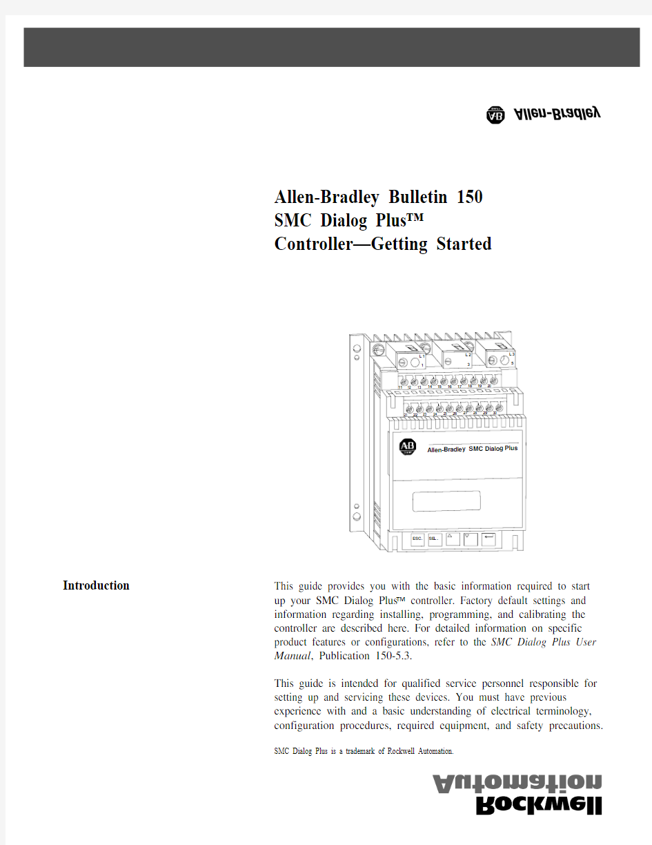
AB软启动器150系列变频器说明书
- 格式:pdf
- 大小:362.11 KB
- 文档页数:12


Allen-Bradley Bulletin 150
SMC Dialog Plus™
Controller—Getting Started
Introduction This guide provides you with the basic information required to start
up your SMC Dialog Plus controller. Factory default settings and
information regarding installing, programming, and calibrating the
controller are described here. For detailed information on specific
product features or configurations, refer to the SMC Dialog Plus User
Manual, Publication 150-5.3.
This guide is intended for qualified service personnel responsible for
setting up and servicing these devices. You must have previous
experience with and a basic understanding of electrical terminology,
configuration procedures, required equipment, and safety precautions.
SMC Dialog Plus is a trademark of Rockwell Automation.
2
Installation The open-style design of the SMC Dialog Plus controller requires that
it be installed in an enclosure. The internal temperature of the
enclosure must be kept within 0…5°C (32…122°F).
The controller is convection cooled. It is important to mount the
controller in a position that allows air to flow vertically through the
power structure. Allow for a minimum of six inches (15 cm) of free
space around all sides of the controller.
Wiring Power Wiring
Refer to the product nameplate for power lug termination information
including:
•Lug wire capacity
•Tightening torque requirements
•Lug kit catalog numbers (97…1000A)
Control Wiring
Refer to the product nameplate for control terminal wire capacity and
tightening torque requirements. Each control terminal will accept a
maximum of two wires.
The SMC Dialog Plus controller accepts control power input of either
100…240VAC, (+10/–15%) single-phase, 50/60Hz or 24V AC/DC.
Refer to the product nameplate prior to applying control power.
Connect control power to the controller at terminals 11 and 12. The
control power requirement for the control module is 40 V A. For
controllers rated 97…1000A, control power is also required for the
heatsink fans as defined in Table A. Depending on the specific
application, additional control circuit transformer V A capacity may be
required.
Table A
Heatsink Fan Power Requirements
3
Control Terminals
Figure 1
SMC Dialog Plus Controller Control Terminals
Table B
Control Terminal Designation
Do not connect any additional loads to these terminals. These “parasitic” loads may cause problems with operation, which may result in false starting and stopping.