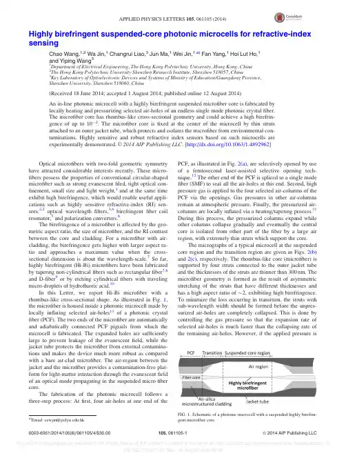
Highly birefringent suspended-core photonic microcells for refractive-index sensingChao Wang,1,2Wa Jin,1Changrui Liao,3Jun Ma,1Wei Jin,1,a)Fan Y ang,1Hoi Lut Ho,1and Yiping Wang 31Department of Electrical Engineering,The Hong Kong Polytechnic University,Hong Kong,China 2The Hong Kong Polytechnic University Shenzhen Research Institute,Shenzhen 518057,China 3Key Laboratory of Optoelectronic Devices and Systems of Ministry of Education/Guangdong Province,Shenzhen University,Shenzhen 518060,China(Received 18June 2014;accepted 1August 2014;published online 12August 2014)An in-line photonic microcell with a highly birefringent suspended microfiber core is fabricated by locally heating and pressurizing selected air-holes of an endless single mode photonic crystal fiber.The microfiber core has rhombus-like cross-sectional geometry and could achieve a high birefrin-gence of up to 10À2.The microfiber core is fixed at the center of the microcell by thin struts attached to an outer jacket tube,which protects and isolates the microfiber from environmental con-taminations.Highly sensitive and robust refractive index sensors based on such microcells areexperimentally demonstrated.VC 2014AIP Publishing LLC .[/10.1063/1.4892962]Optical microfibers with two-fold geometric symmetryhave attracted considerable interests recently.These micro-fibers possess the properties of conventional circular-shaped microfiber such as strong evanescent filed,tight optical con-finement,small size and light weight,1and at the same time exhibit high birefringence,which would enable useful appli-cations such as highly sensitive refractive-index (RI)sen-sors,2,3optical wavelength filters,3,4birefringent fiber coil resonator,5and polarization converters.6The birefringence of a microfiber is affected by the geo-metric aspect ratio,the size of microfiber,and the RI contrast between the core and cladding.For a microfiber with air-cladding,the birefringence gets higher with larger aspect ra-tio and approaches a maximum value when the cross-sectional dimension is about the wavelength-scale.7So far,highly birefringent (Hi-Bi)microfibers have been fabricated by tapering non-cylindrical fibers such as rectangular fiber 7,8and D-fiber 9or by etching cylindrical fibers with traveling micro-droplets of hydrofluoric acid.10In this Letter,we report Hi-Bi microfiber with a rhombus-like cross-sectional shape.As illustrated in Fig.1,the microfiber is housed inside a photonic microcell made by locally inflating selected air-holes 11of a photonic crystal fiber (PCF).The two ends of the microfiber are automatically and adiabatically connected PCF pigtails from which the microcell is fabricated.The expanded holes are sufficiently large to prevent leakage of the evanescent field,while the jacket tube protects the microfiber from external contamina-tions and makes the device much more robust as compared with a bare air-clad microfiber.The air-region between the jacket and the microfiber provides a contamination-free plat-form for light-matter interaction through the evanescent field of an optical mode propagating in the suspended micro fiber core.The fabrication of the photonic microcell follows a three-step process:At first,four air-holes at one end of thePCF,as illustrated in Fig.2(a),are selectively opened by use of a femtosecond laser-assisted selective opening tech-nique.12The other end of the PCF is spliced to a single mode fiber (SMF)to seal all the air-holes at this end.Second,high pressure gas is applied to the four selected air-columns of the PCF via the openings.Gas pressures in other air-columns remain at atmospheric pressure.Finally,the pressurized air-columns are locally inflated via a heating/tapering process.11During this process,the pressurized columns expand while other columns collapse gradually and eventually the central core is isolated from other part of the fiber by a large air region,with extremely thin struts which support the core.The micrographs of a typical microcell at the suspended core region and the transition region are given in Figs.2(b)and 2(c),respectively.The rhombus-like core (microfiber)is supported by four struts connected to the outer jacket tube and the thicknesses of the struts are thinner than 300nm.The microfiber geometry is formed as the result of asymmetric stretching of the struts that have different thicknesses and has a high aspect ratio of $2,exhibiting high birefringence.To minimize the loss occurring in transition,the struts with sub-wavelength width should be formed before the unpres-surized air-holes are completely collapsed.This is done by controlling the gas pressure so that the expansion rate of selected air-holes is much faster than the collapsing rate of the remaining air-holes.However,if the applied pressureisFIG.1.Schematic of a photonic microcell with a suspended highly birefrin-gent microfiber core.a)Email:eewjin@.hk0003-6951/2014/105(6)/061105/4/$30.00VC 2014AIP Publishing LLC 105,061105-1APPLIED PHYSICS LETTERS 105,061105(2014)too high,controlling of the expansion would become diffi-cult,especially when the wall-thickness of the jacket tube becomes thin and high gas pressure would blow up the microcell very quickly.In our experiments,gas pressures in the range from 6to 9bars were used,and the insertion loss of the microcell in the wavelength range from 1250to 1650nm is $0.2dB.The cross-sectional shape of the microfiber core may be modeled approximately by an ellipse with a long to short axis ratio of a/b ¼2,as indicated in the inset of Fig.2(b).The four curved sides of the microfiber are parts of four iden-tical ellipses with long/short axis ratio of 2,and the mini-mum horizontal and vertical separations between ellipses,which correspond to the thicknesses of the struts,are set to be one-twentieth of the short and long axes,respectively.Based on this model,we numerically calculated the phase birefringence B(k )¼j n x (k )2n y (k )j by use of the COMSOL software.Here,n x and n y represent,respectively,the effec-tive RI of the two polarization states of the fundamental HE 11mode.The calculated results are shown in Fig.3.In air,the Hi-Bi microfiber exhibits a theoretical maxi-mal birefringence B max of $3.5Â10À2when the normalized core radius r N ¼r eq /k is around 0.257,where k is the opera-tion wavelength and the equivalent radius r eq is defined as (a Áb)1/2.At k ¼1550nm,the largest birefringence B max would be obtained when the radius r eq is $400nm.The bire-fringence decreases with increasing ambient RI around the microfiber,as shown in Fig.3(a).The peak birefringence B max and the corresponding normalized core radius (r N )as functions of n amb are shown in Fig.3(b).Based on the results in Fig.3(a),the group birefringence G was calculated by using G ¼B Àk Á(dB/d k )and shown in Fig.3(c).The maxi-mum theoretical group birefringence G max reaches $8.2Â10À2at r N %0.19for n amb ¼1.The group birefringence of the Hi-Bi microfiber was measured by use of a Sagnac loop interferometer (SLI)illus-trated in Fig.4(a).The loop coupler is a 3-dB coupler and multiple side-holes were drilled on the outer-jacket of the microcell for liquid and gas filling.A polarization controller (PC)was used in the loop to maximize the fringe contrast.Fig.4(b)shows the measured transmission spectra of a pho-tonic microcell with a rhombus-like microfiber core when the cell is filled with air and a RI liquid with n ¼1.3.The length and the radius of the microfiber are,respectively,L %1cm and r eq %1.6l m.Interference fringes were observed and the fringe spacing is related to the group birefringence (G)and length (L)of the microfiber by Dk %j k 2/G ÁL j .13At the wavelength of $1550nm,G value of the micro-fiber in air was determined to be $4.8Â10À3and $1.5Â10À3when the microcell is filled with the RI liquid.These results are in agreement with the simulation results in Fig.3(c).By monitoring the wavelength at one of the fringe dips as shown in Fig.4(b),the Hi-Bi microfiber microcell may be used as a sensor to measure the RI of the surrounding mate-rial.The sensitivity (S)may be expressed as S ¼d k /dn amb ¼(k /G)Á(dB/dn amb ).2Due to the existence of G ¼0point (refer to Fig.3(c)),the sensitivity around the sign reversing point could be significantly increased.The black and blue lines in Fig.4(c)are,respectively,the calculated sensitivity and fringe space around the wavelength of 1550nm as functions of microfiber radius (r eq )and ambient RI (n amb ).The fringe space is defined as the wavelength sep-aration between adjacent attenuation dips.For a larger n amb value,the higher sensitivity region becomes broader and shifts toward larger r eq values.This would allow high sensi-tivity RI sensors with relatively larger and practicalsizedFIG.2.(a)Schematic of photonic crys-tal fiber endface with four air-holes (la-beled as white circles)opened for pressurization while all other air-holes are sealed.Cross-sectional micro-graphs of a photonic microcell with a highly birefringent (Hi-Bi)microfiber core at (b)the suspended core region and (c)the transition region.Inset of (b):model of Hi-Bi microfiber used for theoreticalcalculation.FIG.3.(a)Calculated phase birefringence of the highly birefringent microfiber as a function of normalized core radius r N (defined as (a Áb)1/2/k ),for different ambient refractive index (n amb ).(b)Shift of birefringence peak with ambient refractive index.(c)Calculated group birefringence as a function of normalized core radius.microfibers.However,the fringe space (D k )also increases with ambient RI and hence would require a longer length of microfiber to ensure at least one fringe dip is located in the operating wavelength range of the source.The innate chambers around the Hi-Bi microfiber pro-vide a compact and isolated space for confining small vol-ume of sample materials and for exploiting light-matter interaction via evanescent field of the microfiber.The filling and emptying of the chambers can be achieved by the micro-channels fabricated on the jacket tube.The inset of Fig.4(a)shows the micro-channels fabricated on the microcell by use of a femtosecond infrared laser micromachining system.As examples of potential applications,the Hi-Bi microcell which is RI-sensitive was tested for temperature and gas pressure measurement by use of the SLI set up shown in Fig.4(a).Temperature measurements were carried out with a liquid-filled Hi-Bi microcell with its spectra shown in Fig.4(b).The RI liquid used was made by R.P.Cargille Lab.,Inc.,and has a RI of n ¼1.3at room temperature and a thermo-optic coefficient dn/dt ¼À3.34Â10À4/ C.The liquid-filled sample was placed in a column oven (ECOMLCO-102)and tested from 25to 95 C.The wave-lengths of the dips change linearly as shown in Fig.5(a)and the dip-a2,which was always present within the wavelength range from 1450to 1650nm,exhibited a high temperature sensitivity of $3nm/ C,corresponding to a RI sensitivity of $9.1Â103nm/RIU.This RI sensitivity is shown as the red dot in Fig.4(c)and agrees well with the theoretical prediction.Measurement of gas pressure was carried out with a sim-ilar Hi-Bi microcell.The fringe spectrum of this microcell was also measured with the SLI and shown in the inset of Fig.5(b).Eight through-holes with diameter of 3–5l m are dilled on the microcell’s jacket tube and on each strut to equalize gas pressure inside and outside the microcell.Then,the microcell was sealed inside a gas chamber made of a glass tube with bore size of $600l m,which was connected to a high pressure nitrogen gas cylinder via a T-tube.Pressurizing the gas within the gas chamber changes the RI of the gas 14and results in a change in the birefringence of the microfiber.The responses of the dip wavelengths to pres-sure from 1bar to 9bars are shown in Fig.5(b).The pressure sensitivity of the microcell is $300pm/bars,corresponding to a RI sensitivity of $1.5Â103nm/RIU.The RI sensitivity is also shown in Fig.4(c)as the un-filled circle and agrees with the theoretical prediction.It would be possible to improve the RI sensitivity by further optimizing the dimen-sions of the Hi-Bi microfiber to make it closer to the maxi-mum sensitivity point.It should be pointed out that the Hi-Bi microcell is com-posed of pure silica which has a low thermo-optic coeffi-cient 15and the effect of temperature-induced silica RI change would have very little effect on the measurement results in Fig.5.To verify this,we tested the temperature response of a microcell sample without material filling.The microcell was first annealed at 1000 C for 5h and then tested from 25to 1000 C.As shown in Fig.5(c),the dip wavelength responded linearly to temperature with a very low temperature sensitivity of 3.5pm/C.FIG.4.(a)Experimental setup of the Sagnac loop interferometer.Inset:micrograph of the through-holes on the jacket tube of the highly birefringent (Hi-Bi)microcell.SMF:single mode fiber;PC:polarization controller;BBS:broad band source;and OSA:optical spectrum analyzer.(b)Measured transmission spec-tra of a Hi-Bi microfiber with ambient refractive index n amb ¼1(black)and 1.3(gray).(c)Calculated refractive index sensitivity (black)and fringe space (blue)around the wavelength of 1550nm with different n amb .Red dots represent samples made in experiments for refractive indexsensing.FIG.5.(a)Measured temperature response of a highly birefringent (Hi-Bi)microcell filled with a refractive index liquid of n ¼1.3.(b)Measured gas pressure response of a Hi-Bi microcell filled with nitrogen gas.(c)Measured temperature response of a Hi-Bi microcell without material filling (up to 1000 C).As compared with traditional prism-based RI sensors, optical-fiber RI sensors offer the advantages of compactness, remote detection capability,and operation in harsh environ-ment.Different opticalfiber sensors such asfiber gra-tings,16,17in-fiber cavity,18multimode interferometer,19and four-wave mixing20have been reported;the Hi-Bi micro-fiber-based sensors have demonstrated competitively high RI sensitivity($104nm/RIU)with additional advantage of low temperature cross-sensitivity($10À7RIU/ C).However, the bare microfiber-based devices are vulnerable to contami-nation21and not easy to handle.The current microcell tech-nology provides a way for embedding a Hi-Bi microfiber within an enclosed compartment and overcomes the prob-lems associated with the use of optical microfibers. Furthermore,the tiny in-fiber cavity surrounding the micro-fiber provides a good platform for strong light-matter inter-action in a reduced space-scale,which would be useful for nanoliter-volume spectroscopy22and bio-chemistry sensing.23In conclusion,a Hi-Bi rhombus-like-shaped microfiber was fabricated and examined theoretically and experimen-tally.The microfiber is embedded inside a jacket tube to form a photonic microcell and adiabatically connects to PCF pigtails at both ends.The birefringence of such micro-fiber could reach up to the order of10À2and exhibits high sensitivity to ambient RI and low sensitivity to tempera-ture.Such photonic microcells are compact and robust, have low loss,and are ideal platforms for sensors and func-tionalized in-fiber devices.Based on such microcells,RI, temperature,and gas pressure sensors are experimentally demonstrated,and the RI sensitivity is$104nm/RIU around n¼1.3.This work was supported by the Natural Science Fundament of China(Grant No.61290313)and the Hong Kong Polytechnic University(Grant No.G-YK62).1L.Tong,F.Zi,X.Guo,and J.Lou,mun.285(23),4641(2012). 2J.Li,L.-P.Sun,S.Gao,Z.Quan,Y.-L.Chang,Y.Ran,L.Jin,and B.-O. Guan,Opt.Lett.36(18),3593(2011).3W.Jin,C.Wang,H.Xuan,and W.Jin,Opt.Lett.38(21),4227(2013).4W.Jin,H.Xuan,and W.Jin,Opt.Lett.39(12),3363(2014).5T.Lee,N.G.R.Broderick,and G.Brambilla,mun.284(7),1837 (2011).6H.Xuan,J.Ma,W.Jin,and W.Jin,Opt.Express22(3),3648(2014).7H.F.Xuan,J.Ju,and W.Jin,Opt.Express18(4),3828(2010).8Y.Jung,G.Brambilla,K.Oh,and D.J.Richardson,Opt.Lett.35(3),378 (2010).9F.Beltr a n-Mej ıa,J.H.Os o rio,C.R.Biazoli,and C.M.B.Cordeiro, J.Lightwave Technol.31(16),2756(2013).10J.C.Mikkelsen and J.K.S.Poon,Opt.Lett.37(13),2601(2012).11C.Wang,W.Jin,J.Ma,Y.Wang,H.Lut Ho,and X.Shi,Opt.Lett. 38(11),1881(2013).12J.Ju,H.Feng Xuan,W.Jin,S.Liu,and H.Lut Ho,Opt.Lett.35(23),3886 (2010).13M.Antkowiak,R.Kotynski,T.Nasilowski,P.Lesiak,J.Wojcik,W. Urbanczyk,F.Berghmans,and H.Thienpont,J.Opt.A:Pure Appl.Opt. 7(12),763(2005).14E.R.Peck and B.N.Khanna,J.Opt.Soc.Am.56(8),1059(1966).15M.J.Weber,Handbook of Optical Materials(CRC Press LLC,2002).16W.Liang,Y.Huang,Y.Xu,R.K.Lee,and A.Yariv,Appl.Phys.Lett. 86(15),151122(2005).17L.Rindorf and O.Bang,Opt.Lett.33(6),563(2008).18C.R.Liao,T.Y.Hu,and D.N.Wang,Opt.Express20(20),22813(2012). 19C.Li,S.-J.Qiu,Y.Chen,F.Xu,and Y.-Q.Lu,IEEE Photonics Technol. Lett.24(19),1771(2012).20M.H.Frosz,A.Stefani,and O.Bang,Opt.Express19(11),10471(2011). 21M.Fujiwara,K.Toubaru,and S.Takeuchi,Opt.Express19(9),8596(2011). 22Y.Cao,W.Jin,L.Hoi Ho,and Z.Liu,Opt.Lett.37(2),214(2012).23S.Heng,M.-C.Nguyen,R.Kostecki,T.M.Monro,and A.D.Abell,RSC Adv.3,8308(2013).。