
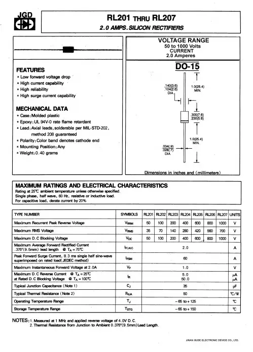
RL204中文资料
- 格式:pdf
- 大小:139.33 KB
- 文档页数:2

IRL1004中文资料
IRL1004
HEXFET ? Power MOSFET
PD - 91702B
Parameter
Typ.
Max.
Units
R θJC Junction-to-Case
–––0.75R θCS Case-to-Sink, Flat, Greased Surface 0.50–––°C/W
R q JA
Junction-to-Ambient
––– 62
Thermal Resistance
l
Logic-Level Gate Drive
l Advanced Process Technology l Ultra Low On-Resistance l
Dynamic dv/dt Rating
l 175°C Operating Temperature l Fast Switching
l Fully Avalanche Rated Fifth Generation HEXFET ? power
MOSFETs from International Rectifier utilize advanced processing
techniques to achieve the lowest possible on-resistance per
silicon area. This benefit, combined with the fast switching speed
and ruggedized device design that HEXFET power MOSFETs are
well known for, provides the designer with an extremely efficient
and reliable device for use in a wide variety of applications.
The TO-220 package is universally preferred for all
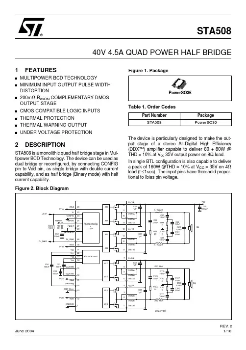
1/10STA508
June 2004 1FEATURES
■MULTIPOWER BCD TECHNOLOGY■MINIMUM INPUT OUTPUT PULSE WIDTH DISTORTION
■200mΩ RdsON COMPLEMENTARY DMOS OUTPUT STAGE
■CMOS COMPATIBLE LOGIC INPUTS■THERMAL PROTECTION■THERMAL WARNING OUTPUT■UNDER VOLTAGE PROTECTION
2DESCRIPTION
STA508 is a monolithic quad half bridge stage in Mul-tipower BCD Technology. The device can be used asdual bridge or reconfigured, by connecting CONFIGpin to Vdd pin, as single bridge with double currentcapability, and as half bridge (Binary mode) with halfcurrent capability.The device is particularly designed to make the out-put stage of a stereo All-Digital High Efficiency(DDX™) amplifier capable to deliver 80 + 80W @THD = 10% at Vcc 35V output power on 8Ω load. In single BTL configuration is also capable to delivera peak of 160W @THD = 10% at VCC = 35V on 4Ωload (t ≤1sec). The input pins have threshold propor-tional to Ibias pin voltage.40V 4.5A QUAD POWER HALF BRIDGE
144®NIC COMPONENTS CORP. www.RFpassives.
com
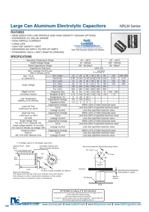
Large Can Aluminum Electrolytic CapacitorsFEATURES• NEW SIZES FOR LOW PROFILE AND HIGH DENSITY DESIGN OPTIONS• EXPANDED CV VALUE RANGE• HIGH RIPPLE CURRENT• LONG LIFE• CAN-TOP SAFETY VENT• DESIGNED AS INPUT FILTER OF SMPS• STANDARD 10mm (.400") SNAP-IN SPACINGNRLM Series
SPECIFICATIONS
(* 47,000µF add 0.14, 68,000µF add 0.35.)
Notice for MountingThe space from the top of the can shall be more than (3mm) from chassis or other construction materials so that safety vent has room to expand in case of emer gen cy.Sleeve Color: Dark BlueCan Top Safety VentInsulation Sleeve and Minus Polarity Marking(4.0mm Leads Available As Option)D+1Max.L ± 26.3 ± 10.810(-)(+)MAXIMUM EX PAN SION FOR SAFETY VENTApprox. 3.0mmRecommended PC Board Mounting Holes:10 ± .1∅= 2 ± 0.1D∅ ± 0.5ChassisPC BoardPRECAUTIONSPlease review the notes on correct use, safety and precautions found on pages T10 & T11 of NIC’s Electrolytic Capacitor catalog. Also found at /precautions If in doubt or uncertainty, please review your specifi c application - process details with NIC’s technical support personnel: tpmg@ Operating Temperature Range
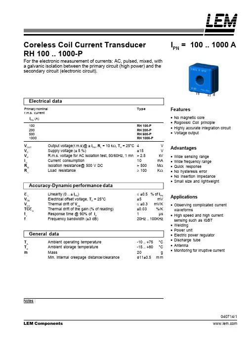
Electrical dataPrimary nominalTyper.m.s. current IPN (A)100RH 100-P200RH 200-P500RH 500-P1000RH 1000-PVOUTOutput voltage(r.m.s)@ ± IPN, RL = 10 kΩ, TA = 25°C4VVCSupply voltage (± 5 %)±15VVdR.m.s. voltage for AC isolation test, 50/60Hz, 1 mn> 2.5kVI CCurrent consumption10mAR
ISIsolation resistance@ 500 V DC
> 500
MΩR LLoad resistance≥ 100KΩAccuracy-Dynamic performance dataεLLinearity (0 .. ± IPN)≤ ±0.5% of IPNVOEElectrical offset voltage, TA = 25°C±5mVVOTThermal drift of VOE≤ ±0.3mV/KTCεGThermal drift of the gain (% of reading)±0.03%/Kt rResponse time @ 90% of IP1µsfFrequency bandwidth (±3 dB)20Hz .. 100KHzGeneral dataTAAmbient operating temperature-10 .. +75°CTSAmbient storage temperature-15 .. +80°CmMass20gMin. internal creepage distance/clearanceø11±0.5mmCoreless Coil Current TransducerRH 100 .. 1000-PFor the electronic measurement of currents: AC, pulsed, mixed, witha galvanic isolation between the primary circuit (high power) and thesecondary circuit (electronic circuit).IPN = 100 .. 1000 A