丰田5A-FE/8A-FE维修手册
- 格式:doc
- 大小:4.03 MB
- 文档页数:98
![[教学研究]丰田5A-FE发动机的整体拆装](https://img.taocdn.com/s1/m/edd5af80360cba1aa811daff.png)
[教学研究]丰田5A-FE发动机的整体拆装丰田5A-FE发动机的整体拆装一、实验参考课时:二、实验目的及要求在发动机和总成拆装过程中,通过对实物的观察、分析、讨论、综合检验、装配、排故、考核,使学生进一一步熟悉和巩固发动机模块中所学的构造、诊断和维修等知识,并形成整体概念,熟悉发动机拆装步骤及主要零件的检验方法:通过对发动机的拆装后,起动发动机,使学生有一定的成就感,进一步提高学生学习专业课的积极三、实验设备及工量具1、丰田5A-FE发动机4台;2、丰田5A-FE发动机控制台4套;3、电源1台;4、常用与专用工具4套;5、汽车专用诊断仪2台;6、发动机内窥镜1套;7、各式量具25套。
四、试验内容发动机解体(以丰田5A-FE发动机为例),解体前认真观察发动机外部各总成、主要零部件的名称、安装位置、连接关系、它们位于哪个机构、哪个系统。
五、实验操作及步骤(一)5A-FE发动机的拆卸1、拆下油底壳的放油螺丝,将发动机内的机油放出;2、拆下各分缸高压线,拆下固定分电器的两颗螺栓,取下分电器总成;3、拆下气门室盖上两条发动机曲轴箱通风管;4、将发电机皮带防护罩拆下;5、将水泵皮带轮的紧固螺栓松开,拆下发电机,取下发电机皮带;6、拆下水泵的皮带轮;7、拆下排气管下方与气缸盖相连的螺母; 8、拆下发动机的机油尺及松开水泵进水口; 9、拆下气门室盖上的螺钉与垫片,取下气门室盖; 10、拆下正时皮带上罩(3号皮带罩); 11、将排气凸轮轴前方的正时齿轮螺母松开;(但暂时不要拆下)12、转动曲轴对一缸上止点记号,检查原有的安装的情况;注意:曲轴皮带轮的记号与正时皮带罩的上止点记号,凸轮轴正时齿轮与排气凸轮轴承盖上的记号。
13、拆下正时皮带下罩(1号皮带罩)的防尘橡胶片;14、松开张紧轮的坚固螺栓,暂时将张紧轮推向前方固定,松开正时皮带;15、拆下进气凸轮轴的第一道轴承盖,转动凸轮轴; 16、用一颗6?20?1的螺栓将进气凸轮上的付斜齿轮与主斜齿轮相连;17、拆下进气与排气凸轮轴的各个轴承盖; 注意:拆卸轴承盖时应注意保持整个凸轮轴的平衡,故同时松开每个轴承盖上的螺栓;拆卸双头螺栓使用10,套筒,棘轮扳手,拆卸单头螺栓则使用10,丁字杆;18、依次取下各个气门挺杆;注意:每一个挺杆都不能够搞乱,各气门挺杆顶端有不同厚度调整气门脚间隙垫片。

丰田8A-FE发动机配气机构的结构与维修(二)
桂健生
【期刊名称】《汽车维护与修理》
【年(卷),期】2004(000)003
【摘要】进、排气凸轮轴的装复要在进气凸轮轴剪式齿轮机构装复后进行。
另外,安装进、排气凸轮轴时要求把它们水平放置,以免损伤气缸盖承受推力的部位。
【总页数】2页(P1-2)
【作者】桂健生
【作者单位】南京汽车制造厂,210037
【正文语种】中文
【中图分类】U4
【相关文献】
1.摩托车二冲程发动机的配气可变机构(一)
2.摩托车二冲程发动机的配气可变机构(二)
3.丰田轿车发动机剪刀式齿轮机构的维修
4.微型汽车462Q汽油发动机
结构及设计特点:(配气机构,传动机构部分)5.发动机配气机构的配气定时研究
与应用
因版权原因,仅展示原文概要,查看原文内容请购买。

110FE–01A65046A65047Front Floor Carpet –FUEL FUEL TANK ASSY11–25992AuthorĂ:DateĂ:2004 COROLLA (RM1037U)Removal & Installation and Disassembly & Reassembly1.REMOVE BENCH TYPE REAR SEAT CUSHION ASSY (See page 72–6, 72–8)2.REMOVE REAR FLOOR SERVICE HOLE COVER (See page 11–16)3.WORK FOR PREVENTING GASOLINE FROM SPILLING OUT(a)Start the engine.(b)After the engine has stopped on the its own, turn the ignition switch to lock.4.DISCONNECT FUEL TANK MAIN TUBE SUB–ASSY (See page 11–16)5.DISCONNECT FUEL EMISSION TUBE SUB–ASSY NO.1 (See page 11–16)6.REMOVE FUEL TANK VENT TUBE SET PLATE (See page 11–16)7.REMOVE FUEL PUMP ASSEMBLY (See page 11–16)8.REMOVE FUEL SUCTION TUBE SET GASKET9.DRAIN FUEL10.REMOVE FLOOR PANEL BRACE FRONT(a)Remove the 2 nuts and floor panel brace front.11.REMOVE EXHAUST PIPE ASSY FRONT(a)Using a clip remover, remove the clip.(b)Tear off the front floor carpet.汽车技师帮技术资料一汽丰田卡罗拉维修维修手册(fuel tank)A65706A65049A6505011–26–FUEL FUEL TANK ASSY993AuthorĂ:DateĂ:2004 COROLLA (RM1037U)(c)Disconnect the oxygen sensor connector.(d)Remove the 2 exhaust pipe supports.(e)Remove the 4 bolts, 4 compression springs and exhaustpipe.12.REMOVE FUEL TANK PROTECTOR NO.1(a)Remove the 5 bolts and fuel tank protector.13.SEPARATE PARKING BRAKE CABLE ASSY NO.2(a)Remove the 2 installing bolts of the parking brake cable.汽车技师帮技术资料一汽丰田卡罗拉维修维修手册(fuel tank)A65051A65052A66709Nylon Tube Fuel TubeConnector Clip Pipe O–ring Fuel Tube Connector A65054A65055–FUEL FUEL TANK ASSY 11–27994AuthorĂ:DateĂ:2004 COROLLA (RM1037U)14.SEPARATE PARKING BRAKE CABLE ASSY NO.3(a)Remove the 2 installing bolts of the parking brake cable.15.DISCONNECT FUEL TANK MAIN TUBE SUB–ASSY (a)Pinch the fuel tube connector clip, and remove the fuel tube connector clip.(b)Pull out the fuel tank main tube.NOTICE:S Check if there is any dirt like mud around the fuel tube connector before this work and clean the dirt away.S Be careful of dirt like mud because the fuel tube con-nector has an O–ring to seal the fuel tube connector and pipe.S Do not use any tool in this work.S Do not bend or twist the nylon tube by force.S After disconnecting, cover the fuel tube connector with a vinyl bag.S When the fuel tube connector and pipe are stuck,pinch the fuel tank main tube between fingers, and turn it carefully to free and then disconnect the fuel tank main tube.16.DISCONNECT FUEL TANK INLET PIPE FUEL HOSE (a)Disconnect the fuel tank inlet filler pipe hose from the fuel tank.17.DISCONNECT FUEL TANK BREATHER HOSE (a)Disconnect the fuel tank breather hose from the fuel tank.汽车技师帮技术资料一汽丰田卡罗拉维修维修手册(fuel tank)A65056Push Pinch A A PinchA65057A65058A65059Nylon Tube Fuel TubeConnector ClipPipe O–ring Fuel Tube Connector A6506011–28–FUEL FUEL TANK ASSY 995AuthorĂ:DateĂ:2004 COROLLA (RM1037U)18.DISCONNECT FUEL TANK VENT HOSE (a)Disconnect the fuel tank bent hose from the charcoal can-ister.(1)Push the connector deep inside.(2)Pinch portion A.(3)Pull out the connector.19.DISCONNECT VALVE TO FUEL FILLER PIPE HOSE (a)Disconnect the valve to fuel filler pipe hose from the fuel tank inlet pipe.20.DISCONNECT FUEL EMISSION TUBE SUB–ASSY NO.1(a)Pinch the fuel tube connector clip and then pull out the fuel emission tube.NOTICE:S Check if there is any dirt like mud around the fuel tube connector before this work and clean the dirt away.S Be careful of dirt like mud because the fuel tube con-nector has an O–ring to seal the fuel tube connector and pipe.S Do not use any tool in this work.S Do not bend or twist the nylon tube by force.S After disconnecting, cover the fuel tube connector with a vinyl bag.S When the fuel tube connector and pipe are stuck,pinch the fuel emission tube between fingers, and turn it carefully to free and then disconnect the fuel emission tube.21.REMOVE FUEL TANK ASSY (a)Set a mission jack to the fuel tank.(b)Remove the 4 bolts, 2 fuel tank bands and fuel tank.汽车技师帮技术资料一汽丰田卡罗拉维修维修手册(fuel tank)A65061A65062A65063A65064A60576Nylon TubeFuel TubeConnector ClipPipe O–ring Fuel TubeConnector –FUEL FUEL TANK ASSY 11–29996AuthorĂ:DateĂ:2004 COROLLA (RM1037U)22.REMOVE FUEL TANK MAIN TUBE SUB–ASSY (a)Remove the fuel tank main tube from the fuel tube clamp and bracket.23.REMOVE FUEL TUBE CLAMP NO.4(a)Remove the bolt and fuel tank clamp.24.REMOVE FUEL TUBE BRACKET (a)Remove the fuel tube bracket from the fuel tank.25.REMOVE FUEL EMISSION TUBE SUB–ASSY NO.1(a)Pinch the fuel tube connector clip and then pull out the fuel emission tube.NOTICE:S Check if there is any dirt like mud around the fuel tube connector before this work and clean the dirt away.S Be careful of dirt like mud because the fuel tube con-nector has an O–ring to seal the fuel tube connector and pipe.S Do not use any tool in this work.S Do not bend or twist the nylon tube by force.S After disconnecting, cover the fuel tube connector with a vinyl bag.S When the fuel tube connector and pipe are stuck,pinch the fuel emission tube between fingers, and turn it carefully to free and then disconnect the fuel emission tube.汽车技师帮技术资料一汽丰田卡罗拉维修维修手册(fuel tank)A65065A65066A65067Clip Remover Gasket A6506811–30–FUEL FUEL TANK ASSY 997AuthorĂ:DateĂ:2004 COROLLA (RM1037U)26.REMOVE FUEL TUBE CLAMP NO.2(a)Remove the fuel tube clamp from the fuel tank.27.REMOVE CHECK VALVE PROTECTOR (a)Using a screwdriver, unlock the claw, and remove the check valve protector by turning it counter clockwise.28.REMOVE FUEL TANK INLET VALVE ASSY (a)Insert a clip remover between the fuel tank inlet valve and gasket, remove the fuel tank inlet valve by gradually pushing it upward.NOTICE:S Work accurately to maintain the sealing performance of the fuel tank inlet valve, since it is made from resin.It is easy to damage by removing and installing forci-bly.S Be sure to install a new fuel tank inlet valve and gas-ket.29.REMOVE CHECK VALVE GASKET (a)Remove the gasket from the fuel tank inlet valve.汽车技师帮技术资料一汽丰田卡罗拉维修维修手册(fuel tank)A65069A65069A65070A65071Apply a light coatof oil–FUEL FUEL TANK ASSY 11–31998AuthorĂ:DateĂ:2004 COROLLA (RM1037U)30.REMOVE FUEL TANK CUSHION NO.1(a)Remove the 7 fuel tank cushions from the fuel tank.31.INSTALL FUEL TANK CUSHION NO.1(a)Install the 7 new fuel tank cushions to the fuel tank.32.INSTALL CHECK VALVE GASKET (a)Install a new gasket to the fuel tank.33.INSTALL FUEL TANK INLET VALVE ASSY (a)Apply a light coat of oil around the fuel tank inlet valve asshown in the illustration, and insert it into the fuel tankwithout force.NOTICE:Be careful not to drop the gasket into the fuel tank.34.INSTALL FUEL EMISSION TUBE SUB–ASSY NO.1(a)Push in the fuel tube connector to the pipe until fuel tube connector makes ”click” sound.NOTICE:S Check if there is any damage or foreign objects on the connected part.S After connecting, check if the fuel tube connector and pipe are securely connected by pullingthem.35.INSTALL FUEL TUBE CLAMP NO.4(a)Install the fuel tube clamp with the bolt.Torque: 6.0 N ⋅m (61 kgf ⋅cm, 53 in.⋅lbf)汽车技师帮技术资料一汽丰田卡罗拉维修维修手册(fuel tank)A51891Tail Pipe Side Gasket –FUEL FUEL TANK ASSY 11–331000AuthorĂ:DateĂ:2004 COROLLA (RM1037U)(c)Install a new gasket on the exhaust pipe (rear side).(d)Install the exhaust pipe with the 4 compression springsand 4 bolts.Torque: 43 N ⋅m (440 kgf ⋅cm, 32 ft ⋅lbf)(e)Install the 2 exhaust pipe supports.(f)Connect the oxygen sensor connector.(g)Install the font floor carpet with a clip.43.INSTALL FLOOR PANEL BRACE FRONT(a)Install the floor panel brace front with the 2 nuts.Torque: 30 N ⋅m (302 kgf ⋅cm, 22 ft ⋅lbf)44.INSTALL FUEL SUCTION TUBE SET GASKET (See page 11–16)45.INSTALL FUEL PUMP ASSEMBLY (See page 11–16)46.INSTALL FUEL TANK VENT TUBE SET PLATE (See page 11–16)47.CONNECT FUEL EMISSION TUBE SUB–ASSY NO.1 (See page 11–16)48.CONNECT FUEL TANK MAIN TUBE SUB–ASSY (See page 11–16)49.CHECK FUEL LEAK (See page 11–1)50.CHECK EXHAUST GAS LEAK51.INSTALL REAR FLOOR SERVICE HOLE COVER (See page 11–16)52.INSTALL BENCH TYPE REAR SEAT CUSHION ASSY (See page 72–6, 72–8)汽车技师帮技术资料一汽丰田卡罗拉维修维修手册(fuel tank)。
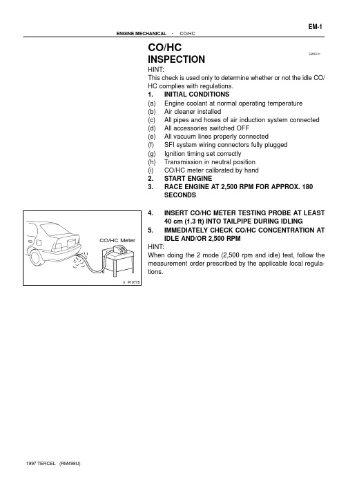
EM18U-01P19776CO/HC Meter-ENGINE MECHANICAL CO/HCEM-1CO/HCINSPECTION HINT:This check is used only to determine whether or not the idle CO/HC complies with regulations.1.INITIAL CONDITIONS (a)Engine coolant at normal operating temperature (b)Air cleaner installed (c)All pipes and hoses of air induction system connected (d)All accessories switched OFF (e)All vacuum lines properly connected (f)SFI system wiring connectors fully plugged (g)Ignition timing set correctly (h)Transmission in neutral position (i)CO/HC meter calibrated by hand 2.START ENGINE 3.RACE ENGINE AT 2,500 RPM FOR APPROX. 180SECONDS 4.INSERT CO/HC METER TESTING PROBE AT LEAST 40 cm (1.3 ft) INTO TAILPIPE DURING IDLING 5.IMMEDIATELY CHECK CO/HC CONCENTRATION AT IDLE AND/OR 2,500 RPM HINT:When doing the 2 mode (2,500 rpm and idle) test, follow the measurement order prescribed by the applicable local regula-tions.EM-2ENGINE MECHANICAL CO/HC-If the CO/HC concentration does not comply with regulations,troubleshoot according to the table below. Check and correctthe cause if necessary.V08293EM0KB-04A05758Compression GaugeCOMPRESSION INSPECTION HINT:If there is lack of power, excessive oil consumption or poor fuel economy, measure the compression pressure.1.WARM UP AND STOP ENGINE Allow the engine to warm up to normal operating temperature.2.REMOVE SPARK PLUGS (See page IG-1)3.CHECK CYLINDER COMPRESSION PRESSURE (a)Insert a compression gauge into the spark plug hole.(b)Fully open the throttle.(c)While cranking the engine, measure the compression pressure.HINT:Always use a fully charged battery to obtain engine revolutions of 250 rpm or more.(d)Repeat steps (a) through (c) for each cylinder.NOTICE:This measurement must be done in as short a time as pression pressure:1,275 kPa (13.0 kgf/cm 2, 185 psi) or more Minimum pressure:981 kPa (10.0 kgf/cm 2, 142 psi)Difference between each cylinder:100 kPa (1.0 kgf/cm 2, 14 psi) or less (e)If the cylinder compression in one or more cylinders is low,pour a small amount of engine oil into the cylinder through the spark plug hole and repeat steps (a) through (c) for cylinders with low compression.L If adding oil helps the compression, chances are that the piston rings and/or cylinder bore are worn or damage.L If pressure stays low, a valve may be sticking or seating is improper, or there may be leakage past the gasket.4.REINSTALL SPARK PLUGSEM0JU-04S05888Charcoal CanisterVSV for EVAP Tie Rod End Battery Front Exhaust PipeLH Engine Under CoverRH Engine Under CoverCompression SpringL GasketRadiatorUpperSupport M/T A/C Compressor Heated Oxygen Sensor(Bank 1 Sensor 2)Clamp L Gasket Compressor Mounting BracketThrottle Cable (A/T)Drive ShaftRadiatorUpperSupportRadiatorIdler Pulley Bracketw/ A/C and w/ o PSAdjusting StrutPS PumpHood L Non-reusable part AcceleratorCableA/T L Snap Ring Air Cleaner AssemblyL Oil Cooler Hose (A/T)ENGINE UNITCOMPONENTSRH Engine Mounting Insulator MAP sensor Hose Brake Booster Vacuum HoseHeater HoseIdle-Up Air Hose (PS)Rear Engine Mounting BracketFuel InletHoseHole Cover Ground StrapClutch Release CylinderSpeedometer CableStarterSpeedometer Cable Starter Control Cable Control CableGround Strap LH Engine Mounting BracketA/T LH Engine Mounting BracketTransaxle x 3Lx 6Ground Strap Clutch CoverClutch DiscM/TL TransaxleLx 3x 5x 6LEM-54-ENGINE MECHANICAL ENGINE UNITEM0JV-03S05838S05848S05840-ENGINE MECHANICAL ENGINE UNITEM-55REMOVAL1.REMOVE BATTERY 2.REMOVE HOOD3.REMOVE ENGINE UNDER COVERS4.DRAIN ENGINE COOLANT5.DRAIN TRANSAXLE OIL (FLUID)6.DISCONNECT VSV FOR EVAP BRACKET7.REMOVE AIR CLEANER ASSEMBLY WITH AIR INTAKE CONNECTOR8.REMOVE RADIATOR (See page CO-16)9.DISCONNECT ACCELERATOR CABLE 10.DISCONNECT FUEL HOSE Remove the union bolt and gaskets, and disconnect the fuel in-let hose.NOTICE:Catch leaking fuel in a container.11.DISCONNECT HOSES Disconnect these hoses:L Brake booster vacuum hose L MAP sensor hose L Heater hoses 12.DISCONNECT SPEEDOMETER CABLE FROM TRANSAXLE 13.w/ PS:DISCONNECT IDLE-UP AIR HOSES FROM AIR CONTROL VALVE 14.DISCONNECT ENGINE WIRE HARNESS Disconnect these connectors and wires:L Oxygen sensor connector L Oil pressure switch connector L Engine coolant temperature sender gauge connector L Engine coolant temperature sensor connector L Camshaft position sensor connector L Fan engine coolant temperature switch connector L A/T only:Lock-up solenoid connector L A/T only:S06150M/T onlyP20565M/TA132 LA/TA242 LA/T EM-56-ENGINE MECHANICAL ENGINE UNITLM/T only:Backup light switch connector L A/T only:No.2 vehicle speed sensor connector L Ground strap L Throttle position sensor connector L IAC valve connector L Injector connectors L Crankshaft position sensor connector L Knock sensor connector L Starter connector and wire L Generator connector and wire 15.M/T only:REMOVE CLUTCH RELEASE CYLINDER WITHOUT DISCONNECTING TUBE (a)Remove the 3 bolts, release cylinder and tube from the transaxle.(b)Disconnect the ground strap.16.M/T:DISCONNECT CONTROL CABLE(S) FROM TRANS-AXLE (a)Remove the clip and plate washer.(b)Remove the retainer from the cable.17.A/T:DISCONNECT CONTROL CABLE(S) FROM TRANS-AXLE (a)Remove the clip and plate washer.(b)Remove the 2 bolts from the LH engine mounting bracket.P20577P20292P20164P20246-ENGINE MECHANICAL ENGINE UNITEM-5718.w/ PS:REMOVE PS PUMP WITHOUT DISCONNECTING HOSES (a)Loosen the 2 bolts, and remove the PS drive belt.(b)Remove the 2 bolts, and disconnect the PS pump from the engine.HINT:Put aside the PS pump, and suspend it.19.w/ A/C:REMOVE A/C COMPRESSOR (a)Disconnect the compressor connector.(b)Remove the 4 compressor mounting bolts.HINT:Put aside the compressor, and suspend it.20.REMOVE FRONT EXHAUST PIPE (a)Disconnect the heated oxygen sensor.(b)Remove the 2 bolts, compression springs and disconnect the exhaust pipe.(c)Remove the bolts and rear clamp.(d)Disconnect the 2 rings and remove the front exhaust pipe.21.REMOVE DRIVE SHAFTS (See page SA-17)22.REMOVE ENGINE WITH TRANSAXLE FROM VEHICLE (a)Install the No.1 engine hanger in the correct direction.Part No.:No.1 engine hanger 12281-11031Bolt 91642-80825(b)Attach the engine sling device to the engine hangers.(c)Remove the rear engine mounting insulator through bolt.(d)Remove charcoal canister (See page EM-12).P20153Ground StrapP20285M/TP20002A132L A/TZ14321A242L A/TLift EM-58-ENGINE MECHANICAL ENGINE UNIT(e)Remove the bolt and disconnect the ground strap.(f)Remove the through bolt, 2 bolts, nut and RH engine mounting insulator.(g)Remove the bolt and disconnect the ground strap.(h)Remove the 5 bolts and LH engine mounting bracket.(i)Lift the engine out of the vehicle slowly and carefully.HINT:Clear the battery carrier support while lowering the transaxle.(j)Place the engine with the transaxle onto the stand.P20167P20161P20245A/T only-ENGINE MECHANICAL ENGINE UNITEM-5923.w/PS:REMOVE PS PUMP ADJUSTING STRUT Remove the 2 bolts and PS pump adjusting strut.24.w/A/C:REMOVE A/C COMPRESSOR MOUNTING BRACKET Remove the 4 bolts and compressor mounting bracket.25.A/T only:REMOVE TORQUE CONVERTER CLUTCH MOUNTING BOLTS (a)Remove the engine rear end plate hole cover.(b)Turn the crankshaft to gain access to each bolt.(c)Hold the crankshaft pulley bolt with a wrench.(d)Remove the 6 bolts.26.REMOVE STARTER (See page ST-4 and ST-18)27.SEPARATE ENGINE AND TRANSAXLEEM0JW-03P20245A/T only P20161P20167Lower EM-60-ENGINE MECHANICAL ENGINE UNITINSTALLATION1.ASSEMBLE ENGINE AND TRANSAXLE M/T: (See page MX-3)A132L A/T: (See page AX-26)A242L A/T: (See page AX-30)2.INSTALL STARTER (See page ST-15 and ST-32)3.A/T only:INSTALL TORQUE CONVERTER CLUTCH MOUNTING BOLTS (a)First, install the gray bolt and then 5 bolts.(b)Tighten the bolts evenly.Torque: 27 N·m (280 kgf·cm, 20 ft·lbf)(c)Install the engine rear end plate hole cover.4.w/A/C:INSTALL A/C COMPRESSOR MOUNTING BRACKET Install the compressor mounting bracket with the 4 bolts.Torque: 27 N·m (280 kgf·cm, 20 ft·lbf)5.w/PS:INSTALL PS PUMP ADJUSTING STRUT Install the PS pump adjusting strut with the 2 bolts.Torque: 21 N·m (210 kgf·cm, 15 ft·lbf)6.INSTALL ENGINE AND TRANSAXLE ASSEMBLY IN VEHICLE (a)Attach the engine sling device to the engine hangers.(b)Lower the engine into the engine compartment.Tilt the transaxle downward, lower the engine and clear the LH engine mounting.NOTICE:Be careful not to hit the PS gear housing, park/neutral posi-P20246P00352P20285 M/TA132L A/TA242L A/T -ENGINE MECHANICAL ENGINE UNITEM-61(c)Keep the engine level, and align RH and LH enginemountings with the body bracket.(d)Attach the RH engine mounting insulator to the mountingbracket and body, and temporarily install the through bolt,2 bolts and nut.(e)Install the LH engine mounting bracket to the transaxleand mounting insulator with the 5 bolts. T orque the bolts.Torque:Bracket to transaxle (bolt head: NT)64 N·m (650 kgf·cm, 47 ft·lbf)Bracket to insulator (bolt head: 7T)49 N·m (490 kgf·cm, 35 ft·lbf)(f)Connect the ground strap with the bolt.Torque: 49 N·m (490 kgf·cm, 35 ft·lbf)P20336P00356P20164EM-62-ENGINE MECHANICAL ENGINE UNIT(g)Install and torque the rear engine mounting insulator through bolt.Torque: 64 N·m (650 kgf·cm, 47 ft·lbf)(h)Remove the engine sling device from the engine.(i)Torque the 2 bolts, nut and through bolt of the RH mount-ing insulator.Torque:Bolt and nut 64 N·m (650 kgf·cm, 47 ft·lbf)Through bolt 73 N·m (740 kgf·cm, 54 ft·lbf)(j)Connect the ground strap with the bolt.(k)Install charcoal canister.(See page EM-17)7.INSTALL DRIVE SHAFTS (See page SA-17)8.INSTALL FRONT EXHAUST PIPE (a)Connect the 2 rings to the front exhaust pipe.(b)Place a new gasket on the exhaust pipe.(c)Connect the exhaust pipe to the exhaust manifold with 2compression springs and 2 bolts.Torque: 62 N·m (630 kgf·cm, 46 ft·lbf)(d)Install the exhaust pipe to the tail pipe with the clamp.Torque: 19 N·m (190 kgf·cm, 14 ft·lbf)(e)Install the heated oxygen sensor.Torque: 44 N·m (450 kgf·cm, 33 ft·lbf)HINT:L Before installing the heated oxygen sensor, twist the sen-sor wire counterclockwise 3 and 1/2 turns.L After installing the heated oxygen sensor, check that the sensor wire is not twisted. If it is twisted, remove the heated oxygen sensor and reinstall it.P20292P20577P20565 M/TP21044 A132L A/TA242L A/T -ENGINE MECHANICAL ENGINE UNITEM-639.w/ A/C:INSTALL A/C COMPRESSOR(a)Install the A/C compressor to the bracket with the 4 bolts.Torque: 25 N·m (250 kgf·cm, 18 ft·lbf)(b)Connect A/C compressor connector.10.w/ PS:INSTALL PS PUMP(a)Install the PS pump and drive belt with the 2 bolts.(b)Adjust the drive belt tension.(See page SR-3)11.M/T:CONNECT CONTROL CABLE(S) TO TRANSAXLE(a)Install the retainer to the cable.(b)Connect the linkage with the plate washer and clip.12.A/T:CONNECT CONTROL CABLE(S) TO TRANSAXLE(a)Install the support bracket to the LH engine mountingbracket with the 2 bolts.(b)Connect the linkage with the plate washer and clip.S06150M/T onlyS05840EM-64-ENGINE MECHANICAL ENGINE UNIT13.M/T only:INSTALL CLUTCH RELEASE CYLINDER Install the release cylinder, tube and ground strap with the 3bolts.Torque: 12 N·m (120 kgf·cm, 9 ft·lbf)14.CONNECT ENGINE WIRE HARNESS Connect these connectors and wires:L Oxygen sensor connector L Oil pressure switch connector L Engine coolant temperature sender gauge connector L Engine coolant temperature sensor connector L Camshaft position sensor connector L Fan engine coolant temperature switch connector L A/T only:Lock-up solenoid connector L A/T only:Park/Neutral position switch connector L M/T only:Backup light switch connector L A/T only:No.2 vehicle speed sensor connector L Ground strap L Throttle position sensor connector L IAC valve connector L Injector connectors L Crankshaft position sensor connector L Knock sensor connector L Starter connector and wire L Generator connector and wire 15.w/ PS:CONNECT IDLE-UP AIR HOSES TO AIR CONTROL VALVE 16.CONNECT SPEEDOMETER CABLE 17.CONNECT HOSES Connect these hoses:(1)Brake booster vacuum hose (2)MAP sensor hose (3)Heater hosesS05838-ENGINE MECHANICAL ENGINE UNIT18.CONNECT FUEL HOSEConnect the fuel inlet hose with the union bolt and 2 new gas-kets.Torque: 29.5 N·m (300 kgf·cm, 22 ft·lbf)19.CONNECT ACCELERATOR CABLE, AND ADJUST IT20.INSTALL RADIATOR(See page CO-22)21.INSTALL AIR CLEANER ASSEMBLY WITH AIR IN-TAKE CONNECTOR22.FILL WITH TRANSAXLE OIL (FLUID)23.FILL WITH ENGINE COOLANT24.INSTALL ENGINE UNDER COVERS25.INSTALL HOOD26.START ENGINE AND CHECK FOR LEAKS27.PERFORM ENGINE ADJUSTMENT28.PERFORM ROAD TESTCheck for abnormal noise, shock, slippage, correct shift pointsand smooth operation.29.RECHECK ENGINE COOLANT AND ENGINE OIL LEV-ELSEM0JS-01P20490P20482SSTP20564Cut Position TapeP20563SST -ENGINE MECHANICAL CYLINDER BLOCKREPLACEMENT1.REPLACE CRANKSHAFT FRONT OIL SEAL HINT:There are 2 methods to replace the oil seal which are as follows:If oil pump is removed from cylinder block (a)Using a screwdriver, pry out the oil seal.(b)Using SST and a hammer, tap in a new oil seal until its sur-face is flush with the oil pump case edge.SST 09309-37010(c)Apply MP grease to the oil seal lip.If oil pump is installed to the cylinder block (d)Using a knife, cut off the oil seal lip.(e)Using a screwdriver, pry out the oil seal.NOTICE:Be careful not to damage the crankshaft.Tape the screwdriver tip.(f)Apply MP grease to a new oil seal lip.(g)Using SST and a hammer, tap in the oil seal until its sur-face is flush with the oil pump case edge.SST 09309-370102.REPLACE CRANKSHAFT REAR OIL SEAL HINT:There are 2 methods to replace the oil seal which are as follows:If rear oil retainer is removed from cylinder block (a)Using a screwdriver and hammer, tap out the oil seal.S07242SST SSTN00264Tape Cut PositionS07243SSTSST EM-82-ENGINE MECHANICAL CYLINDER BLOCK(b)Using SST and a hammer, tap in a new oil seal until its sur-face is flush with the rear oil seal edge.SST 09223-15030, 09550-10012 (09552-10010)(c)Apply MP grease to the oil seal lip.If rear oil seal retainer is installed to cylinder block (d)Using a knife, cut off the oil seal lip.(e)Using a screwdriver, pry out the oil seal.NOTICE:Be careful not to damage the crankshaft.Tape the screwdriver tip.(f)Apply MP grease to a new oil seal lip.(g)Using SST and a hammer, tap in the oil seal until its sur-face is flush with the rear oil seal retainer edge.SST 09223-15030, 09550-10012 (09552-10010)EM0JT-01P20471Front Mark(Cavity)Front Mark (Protrusion)Z08055SST Piston PinSST SST SSTSSTSST SST P205491R2R-ENGINE MECHANICAL CYLINDER BLOCKEM-83REASSEMBLYHINT: Thoroughly clean all parts to be assembled. Before installing the parts, apply new engine oil to all slid-ing and rotating surfaces. Replace all gaskets, O-rings and oil seals with new parts.1.ASSEMBLE PISTON AND CONNECTING ROD (a)Coat the piston pin and pin holes of the piston with engine oil.(b)Align the cavity on the piston with the protrusion on the connecting rod.(c)Using SST, press in the piston pin.SST 09221-25026 (09221-00020, 09221-00030,09221-00130, 09221-00140, 09221-00150)(d)After installing the piston pin, check that when the con-necting rod is aligned with the center of the piston the space between the piston and each end of the piston pin are equal on the left and right sides.HINT:If the piston pin is off-center due to insufficient insertion pres-sure on the piston pin, place a washer at the position indicated by L in the illustration for (c). Then, while checking that the space is equal at the ends of the piston pin on the left and right sides, press in the washer.2.INSTALL PISTON RINGS (a)Install the oil ring expander and 2 side rails by hand.(b)Using a piston ring expander, install the 2 compression rings with the code mark facing upward.Code Mark:P20867FrontExpanderNo.2CompressionRingUpper Side Rail Front Mark (Cavity)No.1Compression Ring Lower Side Rail EM3477EM9416P20550EM-84-ENGINE MECHANICAL CYLINDER BLOCK(c)Position the piston rings so that the ring ends are as shown.NOTICE:Do not align the end gaps.3.INSTALL BEARINGS (a)Align the bearing claw with the groove of the connecting rod or connecting cap.(b)Install the bearings in the connecting rod and connecting rod cap.4.INSTALL MAIN BEARINGS (a)Align the bearing claw with the claw groove of the cylinder block, and push in the 5 upper bearings.NOTICE:Install the bearing with the oil hole in the cylinder block.(b)Align the bearing claw with the claw groove of the main bearing cap, and push in the 5 lower bearings.HINT:A number is marked on each main bearing cap to indicate the illustration position.5.INSTALL UPPER THRUST WASHERS Install the 2 thrust washers under the No.3 journal position with the oil grooves facing outward.6.PLACE CRANKSHAFT ON CYLINDER BLOCKP20551P20530FrontZ1429112345678910EM3480Front Mark(Cavity)Front Push-ENGINE MECHANICAL CYLINDER BLOCKEM-857.INSTALL MAIN BEARING CAPS AND LOWER THRUST WASHERS (a)Install the 2 thrust washers on the No.3 bearing cap with the oil grooves facing outward.(b)Install the 5 main bearing caps in their proper locations.HINT:Each bearing cap has a number and front mark.(c)Apply a light coat of engine oil on the threads and under the heads of the main bearing caps.(d)Install and uniformly tighten the 10 bolts of the main bear-ing caps, in several passes, in the sequence shown.Torque: 58 N·m (580 kgf·cm, 42 ft·lbf)(e)Check that the crankshaft turns smoothly.(f)Check the crankshaft thrust clearance.(See page EM-68)8.INSTALL PISTON AND CONNECTING ROD ASSEMBLIES (a)Cover the connecting rod bolts with a short piece of hose to protect the crankshaft from damage.(b)Using a piston ring compressor, push the correctly num-bered piston and connecting rod assemblies into each cylinder with the front mark of the piston facing forward.EM3481Front Mark(Protrusion)Front EM3448P20475Seal Packing A’B’A BA - A’B - B’EM-86-ENGINE MECHANICAL CYLINDER BLOCK9.INSTALL CONNECTING ROD CAPS (a)Match the numbered connecting rod cap with the num-bered connecting rod.(b)Install the connecting rod cap with the front mark facing forward.(c)Apply a light coat of engine oil on the threads and under the nuts of the connecting rod cap.(d)Install and alternately tighten the nuts of the connecting rod cap in several passes.Torque: 40 N·m (400 kgf·cm, 29 ft·lbf)(e)Check that the crankshaft turns smoothly.(f)Check the connecting rod thrust clearance.(See page EM-68)10.INSTALL REAR OIL SEAL RETAINER (a)Remove any old packing (FIPG) material and be careful not to drop any oil on the contact surfaces of the rear oil seal retainer and cylinder block. Using a razor blade and gasket scraper, remove all the old packing (FIPG) material from the gasket sur-faces and sealing groove. Thoroughly clean all components to remove all the loose material. Using a non-residue solvent, clean both sealing surfaces.(b)Apply seal packing to the rear oil seal retainer as shown in the illustration.Seal packing:Part No. 08826-00080 or equivalent Install a nozzle that has been cut to a 2 - 3 mm (0.08- 0.12 in.) opening. Parts must be assembled within 5 minutes of ap-plication. Otherwise the material must be removed and reapplied. Immediately remove nozzle from the tube and rein-stall cap.(c)Install the oil seal retainer with the 4 bolts.Torque: 7.5 N·m (75 kgf·cm, 65 in.·lbf)P2047612 mmHexagon WrenchP00496AdhesiveP20479SST P20750SST-ENGINE MECHANICAL CYLINDER BLOCK EM-8711.INSTALL OIL FILTER UNION Using a 12 mm hexagon wrench, install the oil filter union.Torque: 25 N·m (250 kgf·cm, 18 ft·lbf)12.INSTALL OIL PUMP AND PRESSURE REGULATOR VALVE 13.INSTALL OIL PRESSURE SWITCH (a)Clean the switch threads and cylinder block switch holes of any sealer, oil or foreign materials.Remove any oil with kerosene or gasoline.(b)Apply adhesive to 2 or 3 threads of the switch end.Adhesive:Part No. 08833-00080, THREE BOND 1344,LOCTITE 242 or equivalent (c)Using SST, install the oil pressure switch.SST 09816-30010Torque: 13 N·m (130 kgf·cm, 9 ft·lbf)14.INSTALL OIL FILTER (See page LU-1)15.INSTALL RH ENGINE MOUNTING BRACKET Torque: 58 N·m (590 kgf·cm, 43 ft·lbf)16.INSTALL KNOCK SENSOR Using SST, install the knock sensor.SST 09816-30010Torque: 45 N·m (450 kgf·cm, 33 ft·lbf)P20545EM9412EM7333EM941012345617.INSTALL GENERATOR BRACKET Torque: 24 N·m (240 kgf·cm, 18 ft·lbf)18.INSTALL WATER PUMP WITH WATER INLET PIPE 19.INSTALL OIL DIPSTICK GUIDE AND GENERATOR AD-JUSTING BAR 20.INSTALL CYLINDER HEAD 21.INSTALL TIMING BELT AND PULLEYS 22.REMOVE ENGINE STAND 23.INSTALL REAR END PLATE Torque: 10 N·m (100 kgf·cm, 7 ft·lbf)24.M/T:INSTALL FLYWHEEL (a)Apply adhesive to 2 or 3 threads of new mounting bolt end.Adhesive:Part No. 08833-00070, THREE BOND 1324 or equivalent (b)Install the flywheel on the crankshaft.(c)Install and uniformly tighten the mounting bolts, in several passes, in the sequence shown.Torque: 90 N·m (900 kgf·cm, 65 ft·lbf)25.A/T:INSTALL DRIVE PLATE (See step 24)26.M/T:INSTALL CLUTCH DISC AND COVEREM0JR-01P00393Z07983P00390FrontINSPECTION1.CLEAN CYLINDER BLOCK (a)Remove gasket ing a gasket scraper, remove all the gasket material from the top surface of the cylinder block.(b)Clean cylinder ing a soft brush and solvent, thoroughly clean the cylin-der block.2.INSPECT TOP SURFACE OF CYLINDER BLOCK FOR FLATNESS Using a precision straight edge and feeler gauge, measure the surfaces contacting the cylinder head gasket for warpage.Maximum warpage: 0.05 mm (0.0020 in.)If warpage is greater than maximum, replace the cylinder block.3.INSPECT CYLINDER FOR VERTICAL SCRATCHES Visually check the cylinder for vertical scratches.If deep scratches are present, replace the cylinder block.4.INSPECT CYLINDER BORE DIAMETER HINT:There are 3 sizes of the standard cylinder bore diameter,marked ”1”, ”2” and ”3” accordingly. The mark is stamped on the top of the cylinder block.P20484Front ThrustDirectionAxialDirection10 mm(0.39 in.)10 mm(0.39 in.)A B C P20491P20541-ENGINE MECHANICAL CYLINDER BLOCK EM-77Using a cylinder gauge, measure the cylinder bore diameter at positions A, B and C in the thrust and axial directions.Standard diameter:Maximum diameter:74.23 mm (2.9224 in.)If the diameter is greater than maximum, replace the cylinder block.5.REMOVE CYLINDER RIDGE If the wear is less than 0.2 mm (0.008 in.), using a ridge reamer,grind the top of the cylinder.6.CLEAN PISTON (a)Using a gasket scraper, remove the carbon from the pis-ton top.(b)Using a groove cleaning tool or broken ring, clean the ring grooves.P20539P20561Mark 1, 2 or 3Front mark (Cavity)P2047423 mm (0.91 in.)Mark 1, 2 or 3FrontFront mark (Cavity)Mark 1, 2 or 3EM-78-ENGINE MECHANICAL CYLINDER BLOCK(c)Using a soft brush and solvent, thoroughly clean the pis-ton.NOTICE:Do not damage the piston.7.INSPECT PISTON OIL CLEARANCE HINT:There are 3 sizes of the standard piston diameter, marked ”1”,”2” and ”3” accordingly. The mark is stamped on the piston top.(a)Using a micrometer, measure the piston diameter at right angles to the piston pin center line, 23 mm (0.91 in.) from the piston head.Piston diameter:(b)Measure the cylinder bore diameter in the thrust direc-tions. (See step 4)(c)Subtract the piston diameter measurement from the cylin-der bore diameter measurement.Standard oil clearance:0.09 - 0.11 mm (0.0035 - 0.0043 in.)Maximum oil clearance:0.13 mm (0.0051 in.)If the oil clearance is greater than maximum, replace all 4 pis-tons. If necessary, replace the cylinder block.HINT:(Use new cylinder block):Use a piston with the same number mark as the cylinder bore diameter marked on the cylinder block.P20540P20527Top of Cylinder Block110 mm (4.33 in.,)EM7639-ENGINE MECHANICAL CYLINDER BLOCKEM-798.INSPECT PISTON RING GROOVE CLEARANCE Using a feeler gauge, measure the clearance between new pis-ton ring and the wall of the ring groove.Ring groove clearance:If the oil clearance is greater than maximum, replace the piston.9.INSPECT PISTON RING END GAP (a)Insert the piston ring into the cylinder bore.(b)Using a piston, push the piston ring a little beyond the bot-tom of the ring travel, 110 mm (4.33 in.) from the top of the cylinder block.(c)Using a feeler gauge, measure the end gap.Standard end gap:Maximum end gap:If the end gap is greater than maximum, replace the piston ring.If necessary, replace the cylinder block.10.INSPECT CONNECTING RODS Using a rod aligner, check the connecting rod alignment.L Check for out-of-alignment.Maximum out-of-alignment:0.03 mm (0.0012 in.) per 100 mm (3.94 in.)If out-of-alignment is greater than maximum, replace the con-necting rod assembly.N00302 EM3208N00295L Check for twistMaximum twist:0.05 mm (0.0020 in.) per 100 mm (3.94 in.)If twist is greater than maximum, replace the connecting rod as-sembly.HINT:If replacing the connection rods, replace the same number of connecting rod bearings as that of new connecting rod caps.11.INSPECT CRANKSHAFT FOR RUNOUT(a)Place the crankshaft on V-blocks.(b)Using a dial indicator, measure the circle runout at thecenter journal.Maximum circle runout: 0.06 mm (0.0024 in.)If the circle runout is greater than maximum, replace the crank-shaft.12.INSPECT MAIN JOURNALS AND CRANK PINS(a)Using a micrometer, measure the diameter of each mainjournal and crank pin.Main journal diameter:Crank pin diameter:If the diameter is not as specified, check the oil clearance (See steps 3 and 6 in cylinder block disassembly). If necessary, grind or replace the crankshaft.(b)Check each main journal and crank pin for taper and out-of-round as shown.Maximum taper:0.08 mm (0.0031 in.)Maximum out-of-round:0.07 mm (0.0028 in.)If the taper and out-of-round is greater than maximum, replace the crankshaft.13.IF NECESSARY, GRIND AND HONE MAINJOURNALS AND/OR CRANK PINS(a)Grind and hone the main journals and/or crank pins to thefinished undersized diameter (See procedure in step 2).(b)Install new main journal and/or crank pin undersizedbearings.EM0JQ-04EM9411EM9412P20480SSTP20478SST12 mmHexagonWrench DISASSEMBLY1.M/T:REMOVE CLUTCH COVER AND DISC 2.REMOVE FLYWHEEL (M/T) OR DRIVE PLATE (A/T)3.REMOVE REAR END PLATE 4.INSTALL ENGINE TO ENGINE STAND FOR DISASSEMBLY 5.REMOVE TIMING BELT AND PULLEYS 6.REMOVE CYLINDER HEAD 7.REMOVE OIL DIPSTICK GUIDE AND GENERATOR ADJUSTING BAR 8.REMOVE WATER PUMP WITH WATER INLET PIPE 9.REMOVE GENERATOR BRACKET 10.REMOVE KNOCK SENSOR Using SST, remove the knock sensor.SST 09816-3001011.REMOVE RH ENGINE MOUNTING BRACKET 12.REMOVE OIL FILTER 13.REMOVE OIL PRESSURE SWITCH Using SST, remove the oil pressure switch.SST 09816-3001014.REMOVE OIL PUMP AND PRESSURE REGULATOR VALVE 15.REMOVE OIL FILTER UNION Using a 12 mm hexagon wrench, remove the oil filter union.。

DOWNLOAD 4S FE ENGINE MANUAL TOYOTA PDF EBOOK EPUB MOBI4s fe engine manual toyota4s fe engine manual pdf4s fe engine manual toyotaSave this Book to Read 4s fe toyota engine service manual PDF eBook at our Online Library. Get 4s fe toyota engine service manual PDF file for free from our online library4s fe engine manual pdf4s fe toyota engine service manual by JamesAust2323 - Issuu4s fe engine manual toyota4s Fe Toyota Engine Service Manual.pdf - Free download Ebook, Handbook, Textbook, User Guide PDF files on the internet quickly and easily.4s fe toyota engine service manual by JamesAust2323 - Issuu4s Fe Toyota Engine Service Manual.pdf - Free Download4s fe engine manual toyotaToyota 4sfe Engine Manual.pdf - Free download Ebook, Handbook, Textbook, User Guide PDF files on the internet quickly and easily. ... Toyota 4sfe Engine Manual Toyota 4s Fe Engine Manual Pdf Toyota 2e Engine Manual Pdf Toyota 2e Engine Manual Toyota 2e Engine Workshop Manual Toyota 3s-fe Engine Repair Manual Pdf Toyota L 2l 2l-t Engine Repair ...4s Fe Toyota Engine Service Manual.pdf - Free DownloadToyota 4sfe Engine Manual.pdf - Free Download4s fe engine manual toyotaWorkshop Repair and Service Manuals toyota All Models Free OnlineToyota 4sfe Engine Manual.pdf - Free DownloadToyota Workshop Manuals4s fe engine manual toyotaView and Download Toyota 4A-FE repair manual online. 4A-FE Engine pdf manual download. Also for: 4a-ge.Toyota Workshop ManualsTOYOTA 4A-FE REPAIR MANUAL Pdf Download.4s fe engine manual toyotaManual Toyota 4s-fe.pdf - Free download Ebook, Handbook, Textbook, User Guide PDF files on the internet quickly and easily.TOYOTA 4A-FE REPAIR MANUAL Pdf Download.Manual Toyota 4s-fe.pdf - Free Download4s fe engine manual toyotaThere were both 4S-Fi (central point fuel injection) and 4S-FE (multi-point fuel injection) versions. 5S. The 5S engine was essentially the same basic design as the 3S, but features a slightly increased bore and an increased stroke (87.1 x 90.9 mm). The total displacement was thus increased to 2.2 L (2,164 cc).Manual Toyota 4s-fe.pdf - Free DownloadToyota S engine - Wikipedia4s fe engine manual toyotaToyota 3S-FE Engine Repair Manual (RM395). It is commonly used in the: Camry 1987–1992, CelicaT160/T180/T200, Carina 1987–1992, Carina 1988–2001, Caldina 1992–2002, Carina ED 1990–1992 and E 1993–1998, Corona T170/T190, Avensis 1997–2000, RAV4, 1994–2000, Picnic/Ipsum 1996–2002.Toyota S engine - WikipediaPDF ONLINE - Toyota 3S-FE Engine Repair Manual (RM395)4s fe engine manual toyotaToyota 3s-fe Engine Repair Manual Pdf.pdf - Free download Ebook, Handbook, Textbook, User Guide PDF files on the internet quickly and easily.PDF ONLINE - Toyota 3S-FE Engine Repair Manual (RM395)Toyota 3s-fe Engine Repair Manual Pdf.pdf - Free Download4s fe engine manual toyota4A-FE Engine INTRODUCTION - Identification Information, General Repair Instructions 4A-GE Engine INOl 16 IN0035 IDENTIFICATION INFORMATION ENGINE SERIAL NUMBER The engine serial number is stamped on the left side of the cylinder block. GENE_RAL REPAIR INSTRUCTIONS 1. Use fender, seat and floor covers to keep the vehicle clean and prevent damage. 2.Toyota 3s-fe Engine Repair Manual Pdf.pdf - Free DownloadTOYOTA 4A-FE, 4A-GE NGINE REPAIR MANUAL4s fe engine manual toyota17.92MB ENGINE SERVICE MANUAL FOR 4S FE As Pdf, ENGINE FOR 4S FE MANUAL SERVICE As Docx, 4S MANUAL ENGINE FE SERVICE FOR As Pptx ENGINE SERVICE MANUAL FOR 4S FE How easy reading concept can improve to be an effective person? ENGINE SERVICE MANUAL FOR 4S FE review is a very simple task. Yet, how many people can be lazy to read?TOYOTA 4A-FE, 4A-GE NGINE REPAIR MANUAL17.92MB ENGINE SERVICE MANUAL FOR 4S FE As Pdf, ENGINE FOR4s fe engine manual toyota5S–FE Engine download Repair Manual. HOW TO PROCEED WITH TROUBLESHOOTING. The Engine Control System broadly consists of the sensors, Engine Control Module (ECM) and actuators. The ECM receives signals from various sensors, judges the operating conditions and determines the optimum injection duration, timing, ignition timing and idle speed.17.92MB ENGINE SERVICE MANUAL FOR 4S FE As Pdf, ENGINE FOREngine 5S–FE - Wiring Diagrams - 4s fe engine manual toyotaOn the next page select the specific PDF that you want to access. For most vehicles this means you’ll filter through the various engine models and problems that are associated with specific car. You’ll then be shown the first 10 pages of the manual, scroll down and click ‘show full PDF’.Engine 5S–FE - Wiring Diagrams - Hyundai Workshop Repair | Owners Manuals (100% Free)4s fe engine manual toyotaView and Download Toyota 3S-GE repair manual online. 3S-GE Engine pdf manual download. Also for: 3s-gte, 5s-fe. Hyundai Workshop Repair | Owners Manuals (100% Free)TOYOTA 3S-GE REPAIR MANUAL Pdf Download.4s fe engine manual toyotaThe 4A–FE engine is an in–line, 4–cylinder engine with the cylinders numbered 1 – 2 – 3 – 4 from the front. The crankshaft is supported by 5 bearings ...TOYOTA 3S-GE REPAIR MANUAL Pdf Download.TOYOTA ENGINE MANUAL 4A-FE, 3S-GTE, 5S-FE4s fe engine manual toyotaToyota 1ZZ-FE, 3ZZ-FE Engine Repair Manual (RM1099E). Generally repair operations can be separated in the following 3 main processes: 1. Diagnosis 2. Removing and Installing, Replacing, Disassembling, Installing and Checking, Adjusting 3. Final InspectionTOYOTA ENGINE MANUAL 4A-FE, 3S-GTE, 5S-FEPDF ONLINE - Toyota 1ZZ-FE, 3ZZ-FE Engine Repair Manual4s fe engine manual toyotaThe 3S-FE engine is fitted with cast iron internals, whereas the 3S-GE/GELU engines have forged internals. ENGINE (RM395) Part Number: PZ471-M0395-CA English Repair Manual ENGINE 3S-FE engine, for vehicles from Oct. 1997 to Dec. 2002 production. The Toyota 3S-FE is a 16-valve 2.0L twin camshaft, single cam gear engine built by Toyota from 1986 ...PDF ONLINE - Toyota 1ZZ-FE, 3ZZ-FE Engine Repair ManualToyota 3S-FE Engine Repair Manual (RM395) - Pdf Online4s fe engine manual toyotaToyota 4S-FE/Fi engine reliability, problems and repair. In 1987, a new 4S 1.8-liter engine replaced the Toyota 1S. It origins from the 3S cylinder unit, in which the cylinder diameter was diminished to 82.5 mm. The crankshaft remained intact. The engine was also equipped with the different intake and exhaust manifolds.Toyota 3S-FE Engine Repair Manual (RM395) - Pdf OnlineToyota 4S Engine | Specs, features, tuning, engine oil4s fe engine manual toyotaToyota 4Runner Repair Manual PDF 2002-2009 Engines Covered: 4.0 L 1GR-FE V6 4.7 L 2UZ-FE V8 (MY2003-2004) 4.7 L 2UZ-FE with VVT-i (MY2005-2009) 3.0 L 1KZ-TE I4 turbodiesel (Latin America) 3.0 L 1KD-FTV I4 Transmissions…Toyota 4S Engine | Specs, features, tuning, engine oilToyota Repair Manuals - Only Repair Manuals4s fe engine manual toyotaToyota Corona repair manual, fault codes, wiring diagrams PDF free download See also: Toyota Service Manuals Toyota Engine Repair Manual Toyota Corolla repair manual The repair, operation and maintenance manual for Toyota Corona vehicles equipped with 4A-FE (1.6 liter), 7A-FE (1.8 liter), 3S-FE (2.0 liter), 3S- GE (2.0 liters), 4S-FE (1.8 liters), 5E-FE (1.5 liters), as well as diesel engines ...Toyota Repair Manuals - Only Repair ManualsToyota Corona | 4s fe engine manual toyotaWorkshop manual diesel engine Toyota 3S-FE engine (2.0 l) with fuel injection and 3S-FSE (2.0 l) with direct injection installed on Toyota cars in the 1996-2003 biennium. The manual provides information about the features of the diagnosis and repair of the engine with gasoline direct injection system Toyota (D4) for all car engine 3S-FSE.Toyota Corona | TOYOTA 3S-FE, 3S-FSE 1996-2003 repair manual engine4s fe engine manual toyotaCars 2WD, 4WD with gasoline engines 4S-FE, 3S-FE, 3S-GE Electric equipment of a body Mounting block Relays and fuses (fuse box) Power supply Connector for additional equipment Charging system, buzzer, start-up system Electric system of engine management system Toyota Carina ED Corona EXIV Electric motors of fansTOYOTA 3S-FE, 3S-FSE 1996-2003 repair manual engineToyota Carina PDF Manual - Wiring Diagrams4s fe engine manual toyotaReviewed by Pete C. Gunn For your safety and comfort, read carefully e-Books toyota 4e fe engine repair manual PDFthis Our Library Download File Free PDF Ebook.Toyota Carina PDF Manual - Wiring DiagramsTOYOTA 4E FE ENGINE REPAIR MANUAL PDF - Amazon S34s fe engine manual toyotaToyota 1AZ-FE Engine Repair Manual (RM865E) PDF free onlineThis manual is made in accordance with SAEJ2008.Generally repair operations can be separated in the following 3 main processes: Diagnosis Removing and Installing, Replacing, Disassembling,TOYOTA 4E FE ENGINE REPAIR MANUAL PDF - Amazon S3Toyota 1AZ-FE Engine Repair Manual (RM865E) - Pdf Online4s fe engine manual toyotaTOYOTA 5A ENGINE MANUAL PDF Download: TOYOTA 5A ENGINE MANUAL PDF TOYOTA 5A ENGINE MANUAL PDF - Are you looking for Ebook toyota 5a engine manual PDF? You will be glad to know that right now toyota 5a engine manual PDF is available on our online library. With our online resources, you can find toyota 5a engine manual or just about any type ofToyota 1AZ-FE Engine Repair Manual (RM865E) - Pdf OnlineTOYOTA 5A ENGINE MANUAL PDF - Amazon S34s fe engine manual toyotaPage 1 3S-GE and 3S-GTE ENGINE Pub.No.RM164E...; Page 460 The following pages have been added as a bonus to the OFFICIAL MR2 Manuals by Toyota. Much of the information in the following pages has been put together by enthusiastic owners or from in information gathered from the various MR2 Forums.TOYOTA 5A ENGINE MANUAL PDF - Amazon S3TOYOTA 3S-GE REPAIR MANUAL Pdf Download.4s fe engine manual toyotaengine mechanical ± fan and generator v belt (2az±fe) 14±5 author: date: 1527 2002 camry repair manual (rm881u) fan and generator v belt (2az±fe) replacement 1. remove front wheel rh 2. remove front fender apron seal rh 3. remove engine cover sub±assy no.1 4. remove engine moving control rod w/bracketTOYOTA 3S-GE REPAIR MANUAL Pdf Download.ENGINE MECHANICAL ± ENGINE ASSEMBLY (2AZ±FE) ENGINE4s fe engine manual toyotaPage 1 1NZ-FE ENGINE JDESCRIPTION The 1NZ-FE engine is a in-line, 4-cylinder, 1.5 liter, 16-valve DOHC engine. The VVT-i (Variable Valve Timing-intelligent) system, DIS (Direct Ignition System) and ETCS-i (Electronic Throttle Control System-intelligent) are used on this engine in order to realize high performance, quietness, fuel economy and clean emission.ENGINE MECHANICAL ± ENGINE ASSEMBLY (2AZ±FE) ENGINETOYOTA 1NZ-FE USER MANUAL Pdf Download.4s fe engine manual toyota13.96MB TOYOTA 4S FE WORKSHOP MANUAL As Pdf, TOYOTA WORKSHOP 4S MANUAL FE As Docx, 4S TOYOTA FE WORKSHOP MANUAL As Pptx TOYOTA 4S FE WORKSHOP MANUAL How easy reading concept can improve to be an effective person? TOYOTA 4S FE WORKSHOP MANUAL review is a very simple task. Yet, how many people can be lazy to read?TOYOTA 1NZ-FE USER MANUAL Pdf Download.13.96MB TOYOTA 4S FE WORKSHOP MANUAL As Pdf, TOYOTA4s fe engine manual toyotaHyundai Santa Fe Workshop Manual PDF. This webpage contains Hyundai Santa Fe Workshop Manual PDF used by Hyundai garages, auto repair shops, Hyundai dealerships and home mechanics. With this Hyundai Santa Fe Workshop manual, you can perform every job that could be done by Hyundai garages and mechanics from: changing spark plugs,brake fluids,13.96MB TOYOTA 4S FE WORKSHOP MANUAL As Pdf, TOYOTAHyundai Santa Fe Workshop Manual PDF - Car Repair Manuals4s fe engine manual toyotaThe first letters of the engine serial number represent your engine family and type code. These can be found on the engine data plate, or on your sales order acknowledgment. 2. How do I order a paper copy of OMMs? End users may order paper copies of service, maintenance and workshop manuals for all Perkins engines from their local distributor. Hyundai Santa Fe Workshop Manual PDF - Car Repair ManualsPerkins | Operation and maintenance manuals4s fe engine manual toyotaPublishing platform for digital magazines, interactive publications and online catalogs. Convert documents to beautiful publications and share them worldwide. Title: TOYOTA 1997-2002 3S-FE ENGINE WORKSHOP REPAIR &, Author: Stir John, Length: 4 pages, Published: 2013-08-28Perkins | Operation and maintenance manualsCalaméo - TOYOTA 1997-2002 3S-FE ENGINE WORKSHOP REPAIR4s fe engine manual toyotaToyota 5S–FE Engine Repair Manual (RM547E). Models with this engine: ST204 (US Generation 6 Celica GT),ST184 (US Generation 5 Celica GT, GT-S and SX. Australian Generation 5 Celica SX), SW21 (US Generation 2 MR2 N/A), SXV10 (Camry 1992–96), SXV20 (Camry 1997–01).Calaméo - TOYOTA 1997-2002 3S-FE ENGINE WORKSHOP REPAIRPDF ONLINE - Toyota 5S–FE Engine Repair Manual (RM547E)4s fe engine manual toyota180_ a01434 engine mechanical − engine (3rz−fe) 14−5 land cruiser prado repair manual (rm990e) hint: the idle mixture ad...PDF ONLINE - Toyota 5S–FE Engine Repair Manual (RM547E)ENGINE (3RZ FE) - Moranbah Weather | 4s fe engine manual toyotaDownload 60 Deutz Engine PDF manuals. User manuals, Deutz Engine Operating guides and Service manuals. ENGINE (3RZ FE) - Moranbah Weather | Deutz Engine User Manuals Download - ManualsLib4s fe engine manual toyotaEngine Maintenance / Repair Manual Suitable For Vehicles / Machinery Running The Following Engine/s Toyota1TR-FE 2.0 / 2TR-FE 2.7. Disclaimer We are not the publisher of this resource, this resource is available for free on the internet.Deutz Engine User Manuals Download - ManualsLibToyota 1TR 2.0 / 2TR-FE 2.7 Engine Workshop Maintenance4s fe engine manual toyotaToyota 1AZ-FE/1AZ-FSE/2AZ-FE engine Repair Manual [en].rar – A collection of English manuals on the maintenance and repair of Toyota engines models 1AZ-FE / 1AZ-FSE / 2AZ-FE: 9.7Mb: Download: Toyota1AZ-FE/2AZ-FE/2AD-FTV engine Repair Manual [ru].pdf – Manual in Russian for the maintenance and repair of Toyota engines models 1AZ-FE / 2AZ-FE ...Toyota 1TR 2.0 / 2TR-FE 2.7 Engine Workshop MaintenanceToyota engine repair manual free download | Automotive4s fe engine manual toyotaToyota Corona repair manual, fault codes, wiring diagrams PDF free download See also: Toyota Service ManualsToyota Engine Repair Manual Toyota Corolla repair manual The repair, operation and maintenance manual for Toyota Corona vehicles equipped with 4A-FE (1.6 liter), 7A-FE (1.8 liter), 3S-FE (2.0 liter), 3S- GE (2.0 liters), 4S-FE (1.8 ... Toyota engine repair manual free download | AutomotiveToyota | 4s fe engine manual toyotaOrder today your factory repair manual for Hyundai Santa Fe 2007, Hyundai Santa Fe 2008, Hyundai Santa Fe 2009, Hyundai Santa Fe 2010, Hyundai Santa Fe 2011 OR Hyundai Santa Fe 2012! Google+ ...Toyota | Hyundai Santa Fe 2007 2008 2009 2010 2011 2012 repair manual4s fe engine manual toyotaToyota 1NZ-FE Pdf User Manuals. View online or download Toyota 1NZ-FE User Manual ... Manuals; Brands; Toyota Manuals; Engine; 1NZ-FE; Toyota 1NZ-FE Manuals Manuals and User Guides for Toyota 1NZ-FE. We have 1 Toyota1NZ-FE manual available for free PDF ... 1NZ-FE Engine Description. 2. Engine Specifications. 2. Valve Timing. 3. Features of 1nz ...Hyundai Santa Fe 2007 2008 2009 2010 2011 2012 repair manualToyota 1NZ-FE Manuals4s fe engine manual toyotaHyundai Santa Fe 2013, Hyundai Santa Fe 2014, Hyundai Santa Fe 2015, Hyundai Santa Fe 2016 or Hyundai Santa Fe 2017 genuine factory repair manual! Buy factory manual to learn vehicle maintenance ...Toyota 1NZ-FE ManualsHyundai Santa Fe 2013 2014 2015 2016 2017 repair manual4s fe engine manual toyotaToyota Camry Owners Manual Toyota Camry Service Manual. Toyota Camry Service Manual. Toyota Camry Service Manual. Introduction; Audio & visual systemHyundai Santa Fe 2013 2014 2015 2016 2017 repair manualToyota Camry Service Manual4s fe engine manual toyotaAutomatic engine oil supply replenishment system adopted in the 2TZ-FE engine . Accessory drive system adopted in the 2TZ-FE engine. August. JZ series of in-line, 6-cylinder gasoline engines developed . ... D-4S, a direct-injection system, based on world-first technologies, adopted in the 2GR-FSE engine. 2006.Toyota Camry Service ManualEngines - 4s fe engine manual toyotaHyundai Santa Fe – mid-size crossover, created on the platform Hyundai Sonata. The car was named after the city in New Mexico. In 2001, this model was the first crossover Hyundai, released at the same time as the Ford Escape / Mazda Tribute and Pontiac Aztek.Engines - Hyundai Santa FE PDF Workshop and Repair manuals4s fe engine manual toyotaToyota Repair Manual Pdf Free Download.pdf - Free download Ebook, Handbook, Textbook, User Guide PDF files on the internet quickly and easily. Ebook PDF. ... 1991 Toyota Previa Repair Manual Pdf Toyota 1kz-te Engine Factory Workshop And Repair Manual Download 1991 Toyota Previa Repair Manual Pdffree Download ...Hyundai Santa FE PDF Workshop and Repair manualsToyota Repair Manual Pdf Free Download.pdf - Free Download4s fe engine manual toyotaHyundai Accent Repair Manual 2011-2015 models: Hyundai Accent Fourth Generation 4th Generation Hyundai Accent RB Series Hyundai Accent Blue (Turkey) Hyundai Accent WIT (South Korea, hatchback) Hyundai i25 Accent (Colombia,[40] Israel) Hyundai Fluidic Verna (India)…Toyota Repair Manual Pdf Free Download.pdf - Free DownloadHyundai Repair Manuals - Only Repair Manuals4s fe engine manual toyotaGet toyota 1nz fe engine repair manual PDF file for free from our online library PDF File: toyota 1nz fe engine repair manual. 3rd Edition PDF. So depending on what exactly you are searching, you will be able to choose ebooks to suit your own needs. Here is the access Download Page of TOYOTA 1NZ FE ENGINE REPAIR MANUAL PDF, click this Hyundai Repair Manuals - Only Repair ManualsTOYOTA 1NZ FE ENGINE REPAIR MANUAL PDF4s fe engine manual toyotaHyundai Santa Fe Based on the platform of the Hyundai Sonata, the Hyundai Santa Fe is the first SUV from South Korean auto manufacturer Hyundai. Introduced in 2001, it was at first criticized by the journalists for its obscure look, but the American buyers thought the other way.TOYOTA 1NZ FE ENGINE REPAIR MANUAL PDFHyundai Santa Fe Free Workshop and Repair Manuals4s fe engine manual toyota9 fees to NEVER pay a car dealership. Tips on car buying, how to negotiate, and how to buy a car. - Duration: 17:34. Chevy Dude Recommended for youHyundai Santa Fe Free Workshop and Repair ManualsToyota Engine 1ZZ FE Repair Manual4s fe engine manual toyotaToyota Engine 1ZZ FE Repair Manual。
丰田卡罗拉 1ZR-FE 发动机维修手册故障诊断手册2丰田卡罗拉 1ZR-FE 发动机维修手册故障诊断手册2第一章引言1.1 文档目的本手册旨在提供丰田卡罗拉1ZR-FE发动机的维修指导和故障诊断方法。
1.2 适用范围本手册适用于丰田卡罗拉车型搭载1ZR-FE发动机的维修和故障诊断。
第二章技术规范2.1 发动机信息在本章节中,提供1ZR-FE发动机的基本参数、技术规格和特征。
2.2 发动机构造本章节详细介绍1ZR-FE发动机的构造和主要组成部件,包括气缸、活塞、曲轴等。
2.3 燃油系统在本章节中,提供1ZR-FE发动机燃油系统的详细介绍和相应的维修步骤。
包括燃油喷射器、燃油泵等。
2.4 点火系统本章节介绍1ZR-FE发动机的点火系统构造和工作原理,以及维修和故障诊断方法。
2.5 冷却系统在本章节中,提供1ZR-FE发动机冷却系统的维修和故障诊断指导,包括水泵、散热器等。
第三章维修步骤3.1 维修准备工作本章节介绍进行发动机维修所需的准备工作,包括工具和安全注意事项。
3.2 维修步骤在本章节中,提供1ZR-FE发动机常见故障的维修步骤和维修注意事项,包括拆卸零件、更换部件等。
第四章故障诊断4.1 故障码读取本章节介绍如何读取1ZR-FE发动机的故障码,并提供相应的故障解释和修复建议。
4.2 常见故障诊断在本章节中,1ZR-FE发动机常见故障的症状、原因和诊断方法,以及相应的维修建议。
第五章附件本文档涉及的附件包括:- 1ZR-FE发动机技术规格表- 1ZR-FE发动机电气连接图附录A 法律名词及注释本文所涉及的法律名词及注释包括但不限于:- 汽车排放标准:指根据国家或地区的法律法规,对汽车尾气排放进行限制的标准。
- 污染控制设备:指用于降低或控制汽车尾气排放污染物的设备,如废气净化器等。
丰田车系5A-FE 直列四缸1.5L 16气门DOHC 威驰9、8 68/6000 124/32008A-FE 直列四缸1.3L 16气门DOHC 威驰9、3 64/6000 110/3200 丰田5A FE发动机目前国内天津一汽04年至05年1ZZ-FE 直列四缸1.8L 16气门DOHC、DIS(含铅汽油) 花冠9、5 94/6000 162/44003ZZ-FE 直列四缸1.6L 16气门DOHC、VVT-i、DIS(无铅汽油) 10、5 81/6000 146/44001NZ-FE 直列四缸1.5L 16气门DOHC、VVT-i、DIS(无铅汽油) 威驰花冠2NZ-FE 直列四缸1.3L 16气门DOHC、DIS(含铅汽油) 威驰花冠1MZ-FE V型6缸3.0L 24气门DOHC, 10、5 188/5200 203/4400 佳美94年后1AZ-FE 直列四缸2.0L 16气门DOHC、VVT-i、DIS、ETCS-I 凯美瑞、 RA V4 9、8 108/6000 190/60002AZ-FE 直列四缸2.4L 16气门DOHC、VVT-i、DIS、ETCS-I 凯美瑞大霸王 RA V4 9、8 123/6000 224/40002TR-FE 直列4缸 2.7L 双凸轮轴16气门(VVT-i) 霸道、海狮1GR-FE V型六缸4.0L 霸道、兰德酷路泽(第七代陆地巡洋舰)2GR-FE V型六缸3.5L 24气门DOHC、双VVT-i、DIS、ACIS、ETCS-i 新款凯美瑞10、8 204/6200 346/4700/3GR-FE V型六缸3.0L 24气门DOHC、双VVT-i、DIS 2005款皇冠、锐志10、5 170/6200 300/4400 5GR-FE V型六缸2.5L 24气门DOHC、双VVT-i、DIS 锐志10、0 145/6200 242/44001FZ-FE 直列六缸4.5L 陆地巡洋舰(第六代)2UZ-FE V型八缸4.7L 兰德酷路泽(第七代陆地巡洋舰)1NZ-FXE 1.5升4缸直列双凸轮轴16气门普锐斯1ZR-FE 1.6L DOHC 16气门Dual-VVT-I 卡罗拉10、2 92kW/6000 157/42002ZR-FE 1.8L DOHC 16气门Dual-VVT-I 卡罗拉10、0 98kW/6100 174/40002ZR-FAE 1.8L DOHC 16气门Dual-VVT-I Valvematic 卡罗拉10、0 110kW/6100 179/40003ZR-FE 2.0L DOHC 16气门Dual-VVT-I 10、0 105kW/5600 194/3900 Dual-VVT-I3ZR-FAE 2.0L DOHC 16气门Dual-VVT-I Valvematic 116kW/6200 195/4400 2007年4ZR-FE 1.6L 96、7kW Dual-VVT-i4Zr就是丰田08年最新研发的发动机,ZR系列就是丰田最新研究发动机之一。
丰田5A发动机与8A发动机区别简单认识这两款发动机机械结构基本一样:水冷式4冲程4缸16气门电喷式汽油机,闭环多点电控燃油喷射。
所不同的是排量:丰田5A排量:1498ml,丰田8A排量:1342ml。
动力输出方面,丰田5A排量比8A大,功率扭矩自然较高:丰田5A最大功率:68千瓦,最大扭矩:124Nm/3200rpm(3200转每分时达最大扭矩124牛顿米)丰田8A最大功率:63千瓦/6000转/分,最大扭矩:110牛顿米/5200转/分需说明的是,尽管数据差别不大,但5A出现最大扭矩的转速比8A低很多,表现出来就是低转下动力性比8A好,更符合国人驾驶习惯。
原来的8A和5A发动机,现在采用的是丰田公司的VVT-i发动机。
VVT-i 是一种智能正时可变气门控制系统,作为丰田公司的经典之作,是当今汽车界表较先进的发动机技术之一。
与其他类似技术相比,该系统可连续调节气门正时,实现充沛的扭矩,并且通过控制进气门开启时机,从而降低燃油消耗。
导入VVT-i 发动机后,威驰90km/h等速油耗,1.5L AT小于等于5.6L/100km,1.5L MT小于等于5.8L/100km,省油率达10%以上。
其另一优势是在实现低油耗的同时,创造了更加优异的动力性。
数据显示,威驰1.5L MT VVT-i发动机的扭矩达到130Nm/4400rpm,功率75kW/6000rpm,均优于原先的5A发动机。
(2SZ-FE & 3SZ-FE)新款威驰的VVT-i发动机是否适合04款以前的威驰使用?老的威驰用的丰田8A\5A的发动机,后来该款了,去年的威驰上就是SZ系列发动机了,老的8A被力帆拿去用了效果也不错。
今年即将上市的新款威驰用的乃是最新的丰田双VVT-I发动机,排放更环保更节油!你要是威驰换发动机肯定是车管部门不允许的,因为你的登记证和行驶证上都有车子的发动机号的,改变了绝对过不了年审!故---还不如新买一个!vvt-i可变气门正时系统VVT—i.系统是丰田公司的智能可变气门正时系统的英文缩写。
丰田Toyota维修手册/电路图/技术培训资料丰田Toyota维修手册/电路图/技术培训资料注:以下车型资料为2001--2016年。
后期长期更新。
丰田Toyota维修手册/电路图/技术培训资料注:以下车型资料为2001--2016年。
后期长期更新。
YARiS L致炫维修手册/电路图/技术培训资料雷凌维修手册/电路图/技术培训资料凯美瑞维修手册/电路图/技术培训资料雅力士维修手册/电路图/技术培训资料汉兰达维修手册/电路图/技术培训资料逸致维修手册/电路图/技术培训资料一汽丰田维修手册/电路图/技术培训资料威驰维修手册/电路图/技术培训资料花冠维修手册/电路图/技术培训资料卡罗拉维修手册/电路图/技术培训资料普锐斯维修手册/电路图/技术培训资料锐志维修手册/电路图/技术培训资料皇冠维修手册/电路图/技术培训资料RA V4维修手册/电路图/技术培训资料兰德酷路泽维修手册/电路图/技术培训资料普拉多维修手册/电路图/技术培训资料特锐维修手册/电路图/技术培训资料柯斯达维修手册/电路图/技术培训资料丰田维修手册/电路图/技术培训资料FJ酷路泽维修手册/电路图/技术培训资料Venza威飒维修手册/电路图/技术培训资料兰德酷路泽维修手册/电路图/技术培训资料红杉普拉多维修手册/电路图/技术培训资料丰田RA V4维修手册/电路图/技术培训资料汉兰达维修手册/电路图/技术培训资料埃尔法维修手册/电路图/技术培训资料普瑞维亚维修手册/电路图/技术培训资料Sienna维修手册/电路图/技术培训资料丰田86维修手册/电路图/技术培训资料杰路驰维修手册/电路图/技术培训资料HIACE维修手册/电路图/技术培训资料坦途维修手册/电路图/技术培训资料凯美瑞维修手册/电路图/技术培训资料寶馳名車國際服務中心Bao Chi Super luxury car International Service Center。
1 维修手册 附录 丰田5A-FE/8A-FE发动机机械部分维修手册 目录: 一.部分发动机总成·2 (一)组件·2 (二)大修·5 二.气缸盖总成·47 (一)组件·47 (二)大修·47 三.气缸体总成·69 (一)组件·69 (二)大修·69 2
一.部分发动机总成(5A - FE/8A - FE) (一)组件 3 4 5 (二)大修 1.拆下火花塞 2.拆下通风阀分总成 (a) 拆下通风阀。 (b) 拆下垫片。
3. 拆下气门室盖分总成 (a) 拆下加油盖。 (b) 拆下4个螺母,4个密封垫和气门室盖。
4. 拆下2号正时链条或皮带罩 (a) 拆下4个螺栓和2号正时皮带罩。 6
5. 拆下曲轴齿轮或皮带轮罩分总成。 (a) 拆下2个螺栓和曲轴齿轮罩。
6. 将1号气缸设定在上止点,压缩位置 (a) 转动曲轴皮带轮,将皮带轮槽口对准1号正时皮带罩上的正时标记“O”。 (b) 检查曲轴正时皮带轮的“K”标记与轴承盖的正时标记对准。 否则,转动曲轴一周(3600)。 7
7. 拆下凸轮轴皮带轮 (a) 使用SST拆下皮带轮螺栓。 SST 09213 - 54015, 09330 - 00021 (90105 - 08076) (b) 使用SST拆下曲轴皮带轮。 SST 09950 - 50013 (09951 - 05010, 09952 - 05010 09953 - 05020, 09954 - 05021)
8. 拆下正时链条或皮带罩分总成 (a) 拆下3个螺栓和正时皮带罩。 8
9.拆下正时皮带导轮 10.拆下惰轮张紧弹簧 (a) 旋松惰轮安装螺栓。 (b) 拆下张紧弹簧。
11.拆下正时皮带 提示: 如果重复使用正时皮带,在皮带上画一个方向箭头f按发动机旋转的方向),并如图所示在皮带轮和皮带上做出定位标记。 (a) 拆下正时皮带。 9
12.拆下1号正时皮带惰轮分总成。 (a) 拆下螺栓和l号正时皮带惰轮。
13.拆下横置发动机安装支架 (a) 拆下3个螺栓和发动机右侧安装支架。
14. 拆下曲轴正时皮带轮 (a) 如果不能用手拆下皮带轮,使用2个起子。 注意: 按图示垫上抹布防止损坏。
15.拆下1号发动机吊钩 10
(a) 从发电机支架上拆下螺栓,并拆下1号发动机吊钩。 16.拆下2号发动机吊钩 (a) 从气缸盖上拆下螺栓,并拆下2号发动机吊钩。 17.拆下1号发电机支架 (a) 拆下3个螺栓和1号发电机支架。
18.拆下机油尺导管 (a) 拆下3个螺栓和机油尺导管。 (b) 拆下O-型圈。
19.拆下进水管 11
(a) 拆下2个螺栓和进水管。 (b) 断开进水软管。 (c) 拆下垫片。
20. 拆下进水软管 (a) 从水泵总成上拆下进水软管。 21.拆下水泵总成 (a) 拆下3个螺栓和水泵总成。 (b) 拆下O-型圈。
22.拆下凸轮轴正时皮带轮 (a) 用扳手夹持凸轮轴的六角头部分,并松开皮带轮螺栓。 注意: 小心不要让扳手损坏气缸盖。 (b) 拆下皮带轮螺栓和正时皮带轮。 12
23.拆下凸轮轴 注意: 由于凸轮轴的止推间隙很小,必须保持水平并垂直取出凸轮轴。如果凸轮轴不能保持水平,气缸盖承受轴的推力可能开裂或损坏,造成凸轮轴变形或断裂。为避免如此,必须执行下述步骤。 (a) 转动凸轮轴的六角部分将副齿轮小孔转上来(它定位主齿轮和副齿轮)。 提示: 上述状态允许进气凸轮轴的1、3号气缸凸轮的桃心同时顶到各自挺杆。 (b) 拆下两个螺栓和1号轴承盖。 (c) 使用维修螺栓固定主、副齿轮。 推荐维修螺栓: 螺纹直径 6 mm 螺距 1.0 mm 螺栓长度 16 - 20 mm (0.63 - 0.79 in.)
提示: 拆除凸轮轴时,确信通过上述操作已经消除副齿轮扭转弹簧的弹力。 (d) 按标出的顺序分几次均匀地拧松8个轴承盖螺栓。 (e) 拆下4个轴承盖和凸轮轴。 提示: 如果凸轮轴没有被水平地向上顶起,用两个螺栓重新安装轴承盖。然后向上拉凸轮轴齿轮并交替地旋松,拆下轴承盖螺栓。 注意: 不要用工具或其它物体撬动和用力拆除凸轮轴。 13 14
24.拆下凸轮轴副齿轮 (a) 用台钳固定凸轮轴的六角部分。 注意: 小心不要损坏凸轮轴。 (b) 使用SST逆时针转动副齿轮,拆下维修螺栓。 SST 09960 - 10010 (09962 - 01000, 09963 - 00500) (c) 使用卡环钳拆下卡环。 (d) 拆下波形垫圈,凸轮轴副齿轮和凸轮轴齿轮弹簧。
25. 拆下凸轮轴定位油封 15
(a) 转动2号凸轮轴的六角部分,使定位销位于2号凸轮轴垂直中心线偏右的位置。 提示: 上述角度允许2号凸轮轴的l、3号气缸凸轮的桃心同时顶到各自的挺杆。 (b) 拆下2个螺栓,凸轮轴定位油封和1号轴承盖。 注意: 如果1号轴承盖不能用手拆除,没有带上轴承盖螺栓时,不要试图用力拆。
26.拆下2号凸轮轴 (a) 按标出的顺序分几次均匀地旋松8个轴承盖螺栓。 (b) 拆下2个螺栓和4号轴承盖。 (c) 拆下4个轴承盖和2号凸轮轴。 提示: 如果凸轮轴没有被水平地向上顶起,用两个螺栓重新安装轴承盖。然后向上拉凸轮轴齿轮并交替地旋松和拆下轴承盖螺栓。 注意: 不要用工具或其它物体撬动和用力拆除凸轮轴。 16
27. 拆下气缸盖分总成 (a) 按标出的顺序分几次均匀地旋松10个气缸盖螺栓。 SST 09205 - 16010 注意: 如果螺栓不按正确顺序拆除,有可能损坏气缸盖。 (b) 拆下10个平垫圈。 (c) 从气缸体上的定位销处撬起气缸盖。 (d) 将气缸体放置在长形木块上。 提示: 为了易于拆下气缸盖,在气缸体和气缸盖之间的间隙插入起子撬起气缸盖。 注意: 小心不要损坏气缸体和气缸盖接触表面。 17 28. 拆下气缸垫 29. 拆下油底壳分总成 (a) 拆下19个螺栓和2个螺母。 (b) 在气缸体和油底壳之间插入SST的铲刀,铲掉密封垫并拆下油底壳。 SST 09023 - 00100 注意: · 不要在机油泵体和后油封座上使用SST。 · 小心不要损坏油底壳突缘。 18
30.拆下机油滤清器分总成 (a) 拆下2个螺栓、2个螺母、机油滤清器和垫片。
31.拆下机油泵总成 (a) 从机油泵拆下7个螺栓。 (b) 用一个塑料锤子轻轻敲击机油泵体,拆下机油泵。 (c) 拆下垫片。 19
32. 拆下发动机机油压力开关 (a) 使用SST,拆下发动机机油压力开关。 SST 09816 - 30010
33. 拆下发动机后油封座 (a) 拆下6个螺栓、座圈和垫片。 20
34. 拆下机油泵油封 (a) 使用起子和锤子,敲出机油泵油封。
35. 拆下发动机后油封 (a) 使用起子和锤子,敲出发动机后油封。
36. 拆下火花塞密封套 (a) 弯起通风盖板,以防止密封套滑出。 (b) 使用起子撬出密封套。 21
37.检查正时皮带 注意: · 不要弯曲、扭转或翻转正时皮带。 · 不允许正时皮带接触油、水和蒸汽。 · 安装或拆除凸轮轴固定螺栓时不要利用正时皮带的张力。 如图所示,如果有任何损伤,检查下述要点。 (a) 过早脱落 (1) 检查是否正确安装。 (2) 检查正时盖垫片是否损坏有无正确安装。 (b) 如果皮带上的齿裂纹或损坏,检查凸轮轴或水泵是否抱死。 (c) 如果在皮带表面有明显磨损或裂纹,检查皮带轮是否有破损。 (d) 如果仅在皮带的一侧有磨损或损坏,检查皮带轮的导轮和每个皮带的定位。 (e) 如果皮带齿有明显的磨损,检查正时盖损坏、校正垫片安装和皮带轮齿上的异物。 如果必要,更换正时皮带。 38.检查1号正时皮带惰轮分总成 (a) 检查惰轮转动灵活。 如果必要,更换惰轮。 22
39.检查惰轮张紧弹簧 (a) 测量张紧弹簧的自由长度。 自由长度:36.9 mm (1.453 in.) 如果自由长度不合适,更换弹簧。 (b) 在弹簧标准安装长度下测量张力。 安装张力:(在43.6 mm (1.717 in.》 34 - 38 N(3.5 - 3.9 kgf, 7.7 - 8.6 lbf) 如果安装张力不符合标准,更换弹簧。
40. 安装火花塞密封套 (a) 使用SST和锤子,按图示敲入新密封套。 SST 09550 - 10012 (09552 - 10010, 09556 - 10011) (b) 在密封套唇部涂一薄层MP黄油。 (c) 弯曲通风盖板回到原位。
41. 安装发动机后油封 (a) 使用SST和锤子,敲入新油封直到油封表面与后油封座边缘平齐。 SST 09223 - 15030, 09608 - 30012 (b) 在油封唇部涂MP黄油。