卡罗拉维修手册-车门
- 格式:pdf
- 大小:8.15 MB
- 文档页数:50
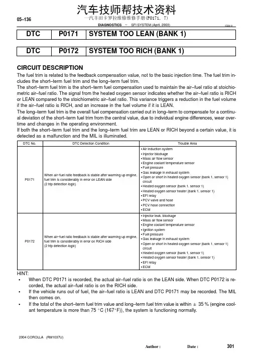
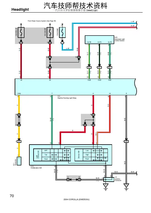
05–136–DIAGNOSTICS SFI SYSTEM (April, 2003)301AuthorĂ:DateĂ:2004 COROLLA (RM1037U)DTCP0171SYSTEM TOO LEAN (BANK 1)DTC P0172SYSTEM TOO RICH (BANK 1)CIRCUIT DESCRIPTIONThe fuel trim is related to the feedback compensation value, not to the basic injection time. The fuel trim in-cludes the short–term fuel trim and the long–term fuel trim.The short–term fuel trim is the short–term fuel compensation used to maintain the air–fuel ratio at stoichio-metric air–fuel ratio. The signal from the heated oxygen sensor indicates whether the air–fuel ratio is RICH or LEAN compared to the stoichiometric air–fuel ratio. This variance triggers a reduction in the fuel volume if the air–fuel ratio is RICH, and an increase in the fuel volume if it is LEAN.The long–term fuel trim is the overall fuel compensation carried out in long–term to compensate for a continu-al deviation of the short–term fuel trim from the central value, due to individual engine differences, wear over-time and changes in the operating environment.If both the short–term fuel trim and the long–term fuel trim are LEAN or RICH beyond a certain value, it is detected as a malfunction and the MIL is illuminated.HINT:SWhen DTC P0171 is recorded, the actual air–fuel ratio is on the LEAN side. When DTC P0172 is re-corded, the actual air–fuel ratio is on the RICH side.SIf the vehicle runs out of fuel, the air–fuel ratio is LEAN and DTC P0171 may be recorded. The MIL then comes on.S If the total of the short–term fuel trim value and long–term fuel trim value is within " 35 % (engine cool-ant temperature is more than 75 _C (167_F)), the system is functioning normally.05DIM–01一汽丰田卡罗拉维修维修手册(PO171, 7)A82386Fuel compensationamount 1.351.00.65+35 (%): Threshold at LEAN –35 (%): Threshold at RICH–DIAGNOSTICS SFI SYSTEM (April, 2003)05–137302AuthorĂ:DateĂ:2004 COROLLA (RM1037U)MONITOR DESCRIPTIONUnder the closed–loop fuel control, fuel injection amounts that deviate from the ECM’s estimated fuel amount will cause a change in the long–term fuel trim compensation value. This long–term fuel trim is ad-justed when there are persistent deviations in the short–term fuel trim values. And the deviation from a simu-lated fuel injection amount by the ECM affects a smoothed fuel trim learning value which is the combination of smoothed short–term fuel trim (fuel feedback compensation value) and smoothed long–term fuel trim (learning value of the air–fuel ratio). When the smoothed fuel trim learning value exceeds the DTC threshold,the ECM interprets this as a fault in the fuel system and sets a DTC.Example:The smoothed fuel trim leaning value is more than +35% or less than –35%, the ECM interprets this as a fail in the fuel system.MONITOR STRATEGY一汽丰田卡罗拉维修维修手册(PO171, 7)05–138–DIAGNOSTICS SFI SYSTEM (April, 2003)303AuthorĂ:DateĂ:2004 COROLLA (RM1037U)TYPICAL ENABLING CONDITIONSTYPICAL MALFUNCTION THRESHOLDSWIRING DIAGRAMRefer to DTC P0130 on page 05–101.INSPECTION PROCEDUREHINT:Hand–held tester only:Narrowing down the trouble area is possible by performing ”A/F CONTROL” ACTIVE TEST (heated oxygen sensor or other trouble areas can be distinguished).(a)Perform ACTIVE TEST using hand–held tester (A/F CONTROL).HINT:”A/F CONTROL” is the ACTIVE TEST which changes the injection volume to –12.5 % or +25 %.(1)Connect the hand–held tester to the DLC3 on the vehicle.(2)Turn the ignition switch ON.(3)Warm up the engine by running the engine speed at 2,500 rpm for approximately 90 seconds.(4)Select the item ”DIAGNOSIS / ENHANCED OBD II / ACTIVE TEST / A/F CONTROL”.(5)Perform ”A/F CONTROL” with the engine in an idle condition (press the right or left button).Result:Heated oxygen sensor reacts in accordance with increase and decrease of injection volume +25 % → rich output: More than 0.5 V,–12.5 % → lean output: Less than 0.4 V一汽丰田卡罗拉维修维修手册(PO171, 7)–DIAGNOSTICS SFI SYSTEM (April, 2003)05–139304AuthorĂ:DateĂ:2004 COROLLA (RM1037U)NOTICE:There is a delay of few seconds in the sensor 1 (front sensor) output, and there is about 20 seconds delay at maximum in the sensor 2 (rear sensor).The following of A/F CONTROL procedure enables the technician to check and graph the voltage outputs of both the heated oxygen sensors.For displaying the graph indication, enter ”ACTIVE TEST / A/F CONTROL / USER DATA”, then select ”O2S B1S1 and O2S B1S2” by pressing ”YES” button and push ”ENTER” button before pressing ”F4” button.HINT:S If different DTCs related to different systems that have terminal E2 as the ground terminal are outputsimultaneously, terminal E2 may be open.S Read freeze frame data using the hand−held tester or the OBD II scan tool. Freeze frame data recordsthe engine conditions when a malfunction is detected. When troubleshooting, it is useful for determin-ing whether the vehicle was running or stopped, the engine was warmed up or not, the air–fuel ratio was lean or rich, etc. at the time of the malfunction.S A high heated oxygen sensor (sensor 1) voltage (0.5 V or more) could be caused by a rich air fuel mix-ture. Check for conditions that would cause the engine to run rich.S A low heated oxygen sensor (sensor 1) voltage (0.4 V or less) could be caused by a lean air fuel mix-ture. Check for conditions that would cause the engine to run lean.一汽丰田卡罗拉维修维修手册(PO171, 7)05–140–DIAGNOSTICS SFI SYSTEM (April, 2003)305AuthorĂ:DateĂ:2004 COROLLA (RM1037U)1CHECK AIR INDUCTION SYSTEM (a)Check the air induction system for vacuum leaks.NG REPAIR OR REPLACE AIR INDUCTION SYSTEMOK2CHECK CONNECTION OF PCV HOSENG REPAIR OR REPLACE PCV HOSEOK3INSPECT FUEL INJECTOR ASSY(INJECTION AND VOLUME) (See page 11–5)NG REPLACE FUEL INJECTOR ASSY (See page 11–10)OK一汽丰田卡罗拉维修维修手册(PO171, 7)A6054832145–200204060801000.10.20.30.51235102030TEMPERA TURE _C(_F)R ESIS T AN CE kΩ(–4)(32)(80)(140)(104)(212)(176)VG E2G+BTHA E2Acceptable05–141306AuthorĂ:DateĂ:2004 COROLLA (RM1037U)OK一汽丰田卡罗拉维修维修手册(PO171, 7)S01196S0169930201053020400.110.30.20.526080100–20(–4)(104)(140)(176)(32)(68)(212)A81700Ohmmeter Acceptable TEMPERATURE _C (_F)R E S I S T A N C E K Ω05–142–DIAGNOSTICS SFI SYSTEM (April, 2003)307AuthorĂ:DateĂ:2004 COROLLA (RM1037U)5INSPECT ENGINE COOLANT TEMPERATURE SENSOR(RESISTANCE)(a)Remove the engine coolant temperature sensor.(b)Measure the resistance between the terminals of the en-gine coolant temperature sensor.Standard:NOTICE:If you checking the engine coolant temperature sensor in water, be careful not to allow water to go into the terminals.After checking, dry the sensor.HINT:Alternate procedure: Connect an ohmmeter to the installed en-gine coolant temperature sensor and read the resistance. Use an infrared thermometer to measure the engine temperature in the immediate vicinity of the sensor. Compare these values to the resistance/temperature graph. Change the engine temper-ature (warm up or allow to cool down) and repeat the test.(c)Reinstall the engine coolant temperature sensor.NG REPLACE ENGINE COOLANT TEMPERATURE SENSOROK6CHECK FOR SPARK AND IGNITION (See page 18–1)NG REPAIR OR REPLACEOK7CHECK FUEL PRESSURE (See page 11–5)(a)Check the fuel pressure (high or low pressure).NG CHECK AND REPLACE FUEL SYSTEMOK8CHECK FOR EXHAUST GAS LEAKAGENG REPAIR OR REPLACE EXHAUST GAS LEAKAGE POINT (See page 15–2)OK一汽丰田卡罗拉维修维修手册(PO171, 7)A85076E3409005–144–DIAGNOSTICS SFI SYSTEM (April, 2003)309AuthorĂ:DateĂ:2004 COROLLA (RM1037U)11INSPECT EFI RELAYOK汽车技师帮技术资料一汽丰田卡罗拉维修维修手册(PO171, 7)A09299A83859Vehicle speed(40 km/h)25mph IG SW OFF40seconds or more 120 seconds or more20 seconds 20 seconds 30 seconds(L 1)(L 3)(L 4)Idling(L 2)(L 3)(L 4)(L 3)40seconds or more 40seconds or more 05–146–DIAGNOSTICSSFI SYSTEM (April, 2003)311AuthorĂ:DateĂ:2004 COROLLA (RM1037U)13REPLACE HEATED OXYGEN SENSORHINT:Check the air induction system for vacuum leaks.GO14PERFORM CONFIRMATION DRIVING PATTERN(a)Connect the hand–held tester to the DLC3. (L 1)(b)Switch the hand–held tester from the normal mode to the check mode (See page 05–11). (L 1)(c)Start the engine and let it idle for 120 seconds or more. (L 2)(d)Drive the vehicle at 25 mph (40 km/h) or more for 40 seconds or more. (L 3)(e)Let the engine idle for 20 seconds or more. (L 4)(f)Perform steps (d) and (e) at least 3 times.HINT:If a malfunction exists, the MIL will be illuminated on the multi–information display during step (f).NOTICE:If the conditions in this test are not strictly followed, detection of a malfunction will not occur. If you do not have the hand–held tester, turn the ignition switch OFF after performing steps from (c) to (f),then perform steps from (c) to (f) again.GO一汽丰田卡罗拉维修维修手册(PO171, 7)05–147312AuthorĂ:DateĂ:2004 COROLLA (RM1037U)一汽丰田卡罗拉维修维修手册(PO171, 7)05–148–DIAGNOSTICSSFI SYSTEM (April, 2003)313AuthorĂ:DateĂ:2004 COROLLA (RM1037U)一汽丰田卡罗拉维修维修手册(PO171, 7)。
SAE Technical Standards Board Rules provide that: “This report is published by SAE to advance the state of technical and engineering sciences. The use of this report is entirely voluntary, and its applicability and suitability for any particular use, including any patent infringement arising therefrom, is the sole responsibility of the user.”SAE reviews each technical report at least every five years at which time it may be reaffirmed, revised, or cancelled. SAE invites your written comments and suggestions.QUESTIONS REGARDING THIS DOCUMENT: (724) 772-8512 FAX: (724) 776-0243TO PLACE A DOCUMENT ORDER; (724) 776-4970 FAX: (724) 776-0790SAE WEB ADDRESS 1.Scope—This SAE Recommended Practice defines the information contained in the header and data fields ofnon-diagnostic messages for automotive serial communications based on SAE J1850 Class B networks. This document describes and specifies the header fields, data fields, field sizes, scaling, representations, and data positions used within messages.The general structure of a SAE J1850 message frame without in-frame response is shown in Figure 1. The structure of a SAE J1850 message with in-frame response is shown in Figure 2. Figures 1 and 2 also show the scope of frame fields defined by this document for non-diagnostic messages. Refer to SAE J1979 for specifications of emissions related diagnostic message header and data fields. Refer to SAE J2190 for the definition of other diagnostic data fields. The description of the network interface hardware, basic protocol definition, the electrical specifications, and the CRC byte are given in SAE J1850.FIGURE 1—SCOPE OF SAE J2178 FOR A SAE J1850 FRAME WITHOUT IN-FRAME RESPONSE (IFR)FIGURE 2—SCOPE OF SAE J2178 FOR A SAE J1850 FRAME WITH IN-FRAME RESPONSE (IFR)SAE J1850 defines two and only two formats of message headers. They are the Single Byte header format and the Consolidated header format. The Consolidated header format has two forms, a Single Byte form anda three byte form. This document covers all of these formats and forms to identify the contents of messageswhich could be sent on a SAE J1850 network.This document consists of four parts, each published separately.SAE J2178-1 (Titled: Detailed Header Formats and Physical Address Assignments) describes the two allowed forms of message header formats, Single Byte and Consolidated. It also contains the physical node address range assignments for the typical sub-systems of an automobile.SAE J2178-2 (Titled: Data Parameter Definitions) defines the standard parametric data which may be exchanged on SAE J1850 (Class B) networks. The parameter scaling, ranges, and transfer functions are specified. Messages which refer to these parametric definitions shall always adhere to these parametric definitions. It is intended that at least one of the definitions for each parameter in this part matches the SAE J1979 definition.SAE J2178-3 (Titled: Frame IDs for Single Byte Forms of Headers) defines the message assignments for the single byte header format and the one byte form of the consolidated header format.SAE J2178-4 (Titled: Message Definition for Three Byte Headers) defines the message assignments for the three byte form of the consolidated header format.2.References2.1Applicable Publications—The following publications form a part of this specification to the extent specifiedherein. Unless otherwise specified, the latest issue of SAE publications shall apply.2.1.1SAE P UBLICATIONS—Available from SAE, 400 Commonwealth Drive, Warrendale, PA 15096-0001.SAE J1213-1—Glossary of Vehicle Networks for Multiplex and Data CommunicationSAE J1850—Class B Data Communication Networks InterfaceSAE J1930—Electrical/Electronic Systems Diagnostic Terms, Definitions, Abbreviations, and AcronymsSAE J1979—E/E Diagnostic Test ModesSAE J2190—Enhanced E/E Diagnostic Test Modes2.1.2ANSI/IEEE P UBLICATION—Available from ANSI, 11 West 42nd Street, New York, NY 10036-8002.ANSI/IEEE 754-1985—IEEE Standard for Binary Floating-Point Arithmetic3.Definitions3.1Data [Data Field]—Data and data field are used interchangeably in this document and they both refer to afield within a frame that may include bytes with parameters pertaining to the message and/or secondary ID and/or extended addresses and/or test modes which further defines a particular message content being exchanged over the network.3.2Extended Address—The extended address is a means to allow a message to be addressed to ageographical location (such as geographic) or zone of the vehicle, independent of any node's physical address.3.3Frame—A frame is one complete transmission of information which may or may not include an In-FrameResponse. The frame is enclosed by the start of frame and end of frame symbols. For Class B networks, each frame contains one and only one message (see "message" definition below).3.4Frame ID—The Frame ID is the header byte for the Single Byte Header format and the one byte form of theconsolidated header format. The definition of the frame ID is found in SAE J2178-3. This header byte defines the target and source and content of the frame.3.5Functional Addressing—Functional addressing allows a message to be addressed or sent to one or morenodes on the network interested in that function. Functional addressing is intended for messages that may be of interest to more than a single node. For example, an exterior lamp "off" message could be sent to all nodes controlling the vehicle exterior lamps by using a functional address. The functional address consists of a primary ID and may include a secondary ID and may also include an extended address.3.6Header [Header Field]—The header (or header field, used interchangeably) is a one or three byte field withina frame which contains information about the message priority, message source and target addressing,message type, and in-frame response type.3.7In-Frame Response (IFR) Type—The IFR type identifies the form of the in-frame response which is expectedwithin that message.3.8Load—The load command indicates the operation of directly replacing the current/existing value of aparameter with the parameter value(s) contained in the message.3.9Message—A message consists of all of the bytes of a frame excluding the delimiter symbols (SOF, EOD,EOF, NB).3.10Modify—The modify command indicates the operation of using the message data parameter value to change(e.g., increment, decrement, or toggle) the current/existing value.3.11Parameter—A parameter is the variable quantity included in some messages. The parameter value, scaling,offset, units, transfer function, etc., are unique to each particular message. (The assigned parameters are contained herein.)3.12Physical Addressing—Physical addressing allows a message to be addressed to a specific node or to allnodes or to a non-existent, null node. The information in this message is of relevance only to a particular node, so the other nodes on the bus should ignore the message, except for the case of the "all nodes" address.3.13Primary ID—The primary ID identifies the target for this functional message. This is the primary discriminatorused to group functions into main categories.3.14Priority—The priority describes the rank order and precedence of a message. Based upon the SAE J1850,Class B arbitration process, the message with the highest priority will win arbitration.3.15Report—A report indicates the transmission of parametric data values, based on: a change of state; a changeof value; on a periodic rate basis; or as a response to a specific request.3.16Request—A request is a command to, or a query for data, or action from another node on the network.3.17Response Data—The response data is the information from a node on the network in response to a requestfrom another node on the network. This may be an in-frame response or a report type of message.3.18Secondary ID—The secondary ID (along with the primary ID or Frame ID) identifies the functional target nodefor a message. The purpose of the secondary ID field within the frame is to further define the function or action being identified by the primary ID.4.Abbreviations and AcronymsA/C - Air ConditioningASC - ASCII Encoded SLOTBCD - Binary Coded Decimal (BCD) SLOTBMM - Bit Mapped with Mask SLOTBMP - Bit Mapped without Mask SLOTCRC - Cyclic Redundancy CheckCS - ChecksumDTC - Diagnostic Trouble CodeEOD - End of DataEOF - End of FrameERR - Error DetectionEV-ETS - Electric Vehicle Energy Transfer SystemEVSE - Electric Vehicle Supply EquipmentHVAC - Heating, Ventilation, Air ConditioningID - IdentifierIFR - In-Frame ResponseLSB - Least Significant Bit/ByteMSB - Most Significant Bit/ByteNB - Normalization BitPID - Parameter IDentification (number, NOT the primary ID, (See Section 7)PKT - Multiple Parameter Packet SLOTPRN - Parameter Reference NumberSED - State Encoded SLOTSFP - Signed Floating Point (Scientific Notation) SLOTSLOT - Scaling, Limit, Offset, and Transfer Function (See Section 8)SNM - 2's Complement Signed Numeric SLOTSOF - Start of FrameUNM - Unsigned Numeric SLOTVIN - Vehicle Identification Number5.General Information5.1Part 1 Overview—The messages defined by this four part document are specified for networks using singlebyte headers or consolidated one and three byte headers as specified in SAE J1850. Sections 6 and 7 of SAE J2178-1 provide the system architecture for the different possible headers used in Class B network communication (see Appendix A for supporting discussion). Section 8 of SAE J2178-1 defines the data fields used by the different header byte formats. Section 9 of SAE J2178-1 defines the physical address assignments.Figure 3 shows an overview of this part (Part 1) which encompasses the different possible messages and their component parts.FIGURE 3—PART 1 OVERVIEWSAE J1850 defines two and only two formats of message headers. They are the Single Byte header format and the Consolidated header format. The Consolidated header format has two forms, identified by the value of the H Bit. The two forms are: a one byte form and a three byte form. The information in the header field for both formats contains target, source, priority and message type information, while the data field contains additional addressing and/or parametric information and/or diagnostic test modes. This information is explicitly defined in some headers and implicitly defined in others. Messages defined by this document (Parts 1, 2, 3, and 4) are classified generally into two types:a.Requests, that is, commands (load or modify) or queries for data, andb.Responses, that is, reports or acknowledgments.When a node generates a request, the target nodes which are responsible for the requested data or function must respond by reporting the requested information or by performing the requested function. For responses (that is, reports or acknowledgments), data information that a node responds with may have been previously requested by another node, or reported by the node when the desired information has changed, or reported by the node on a periodic basis.SAE J2178-1 describes the overall structure of messages. In total, parts 1, 2, 3, and 4:a.Fully define SAE (automotive industry) standard messages.b.Reserve messages for future SAE standardization.c.Reserve messages for manufacturers to allocate, which are typically unique or proprietary to thatmanufacturer.In order to comply with this document, implementations need to use the defined messages on SAE J1850 networks in the exact way that they are defined here. However, there are a large number of message codes that are reserved for each manufacturer to independently allocate.5.2In-Frame Response Field Formats—The total number of bytes in the frame (not including frame delimiters) is12, including the header (1 or 3 depending on header type), data (both in the message and IFR), and single byte CRC. Therefore, the total number of message and IFR data bytes can be 10 if using a single byte header or the one byte form of the consolidated header, or 8 bytes if using the three byte form of the consolidated header.5.2.1I N-F RAME R ESPONSE T YPE 0—The in-frame response type 0 is used to indicate the form without any in-frameresponse.5.2.2I N-F RAME R ESPONSE T YPE 1—The in-frame response type 1 is a single byte response from a singleresponder. The response byte shall be the physical address of a receiver of the message. No CRC byte is included for this response data.5.2.3I N-F RAME R ESPONSE T YPE 2—The in-frame response type 2 is a single byte response from multipleresponders. The response byte(s) shall be the physical address of the receiver(s) of the message. No CRC byte is included for the response data.5.2.4I N-F RAME R ESPONSE T YPE 3—The in-frame response type 3 is a multiple byte response from a singleresponder. The response bytes shall be data (generally not its address) from a single responder. The second CRC byte is included for the data integrity of the response data. The actual in-frame response data shall be one byte in length, as a minimum.Figure 4 illustrates the four IFR types.FIGURE 4—TYPES OF IN-FRAME RESPONSE6.Single Byte Header Messages and Format—For single byte header messages, the entire byte is used todefine the message identifier (ID) as shown in Figure 5. This allows up to 256 unique message identifiers to bedefined. Standard message identifiers that utilize this header format are found in SAE J2178-3.All single byte header messages utilize one of the four in-frame response (IFR) types Figure 4.7.Consolidated Header Messages and Format—The consolidated header format includes both a one byte form and a three byte form.7.1One Byte Form of the Consolidated Header Format—The one byte form utilizes 7 bits for the message identifier thereby allowing up to 128 distinct Ids. The H bit (bit 4) is always a logic "1" signifying the one byte form of the consolidated header. Figure 6 illustrates this message header form. Standard message identifiers that utilize this header form are defined in SAE J2178-3.FIGURE 6—ONE BYTE FORM OF CONSOLIDATED HEADERIn order to accommodate a one byte header form and a three byte header form on the same network, the header type bit (H bit) in the first byte of the message has been defined to indicate the header form. This bit is defined in Table 1.All one byte header form messages of the consolidated header format utilize one of the four in-frame response (IFR) types (see Figure 4).7.2Three Byte Form of the Consolidated Header Format—This header form utilizes the first three bytes of the message. The H bit (bit 4) is always a logic "0" signifying the three byte form. Standard message identifiers that utilize this header form are defined in SAE J2178-4. The remaining seven bits of the first byte contain information about priority (PPP) and message type (KYZZ). The second byte contains the target address information. The target can be either functionally addressed or physically addressed. The third byte contains the physical address of the source of the message. Arbitration is always resolved by the end of the third byte,since the source address must be unique. Figures 7 and 8 illustrate this message header form.FIGURE 7—THREE BYTE FORM OF CONSOLIDATED HEADERTABLE 1—H BIT DEFINITIONH Bit Header Byte Form 0Three Byte Form 1One Byte FormFIGURE 8—FIRST BYTE OF THREE BYTE FORM OF CONSOLIDATED HEADERAll three byte header messages utilize one of the four in-frame response (IFR) types (see Figure 4, 4).7.2.1P RIORITY /T YPE -B YTE 1—The priority/type byte contains information about priority, in-frame response,addressing type, and type modifier. Each of the field definitions is described in the following paragraphs.7.2.1.1Priority (PPP Bits)—The priority field is three bits in length and immediately proceeds the header type (H)bit. The priority bit definition is shown in Table 2. The priority bit assignments for a particular message are manufacturer specific and are not assigned by SAE J2178.7.2.1.2Header Type (H Bit)—In order to accommodate a one byte header form and a three byte header form on the same network, the header type bit (H bit) in the first byte of the message has been defined to indicate the header form. This bit is defined in Table 3.TABLE 2—PRIORITY FIELD ASSIGNMENTSPPP Bits Priority Level 0000Highest0011.0102.0113.1004.1015.1106.1117LowestTABLE 3—H BIT DEFINITIONH Bit Head Byte Form 0Three Byte Form 1One Byte Form7.2.1.3In-Frame Response (K Bit)—The necessity for in-frame response is encoded into a single bit in the priority/type byte. This bit definition is shown in Table 4.TABLE 4—"K" BIT ASSIGNMENTSK Bit In-Frame Response0Required1Not Allowed7.2.1.4Addressing Type (Y Bit)—Message addressing is encoded with a single bit in the priority/type byte. Thisbit definition is shown in Table 5.TABLE 5—"Y" BIT ASSIGNMENTSY Bit Addressing Type0Functional1Physical7.2.1.5Type Modifier (ZZ Bits)—The type modifier is encoded as a two bit field (ZZ) and is used in conjunctionwith the in-frame response bit (K) and the address type bit (Y) to define sixteen message types,see Table 6.TABLE 6—THE SIXTEEN MESSAGE TYPESMsg Response Addressing IFRType KYZZ(K bit)(Y bit)Type Message Type (Name)00000Required Functional2Function10001Required Functional1Broadcast20010Required Functional2Function Query30011Required Functional3Function Read40100Required Physical1Node-to-Node50101Required Physical—Reserved - MFG60110Required Physical—Reserved - SAE70111Required Physical—Reserved - MFG81000Not Allowed Functional0Function Command/Status91001Not Allowed Functional0Function Request/Query101010Not Allowed Functional0Function Ext. Command/Status111011Not Allowed Functional0Function Ext. Request/Query121100Not Allowed Physical0Node-to-Node131101Not Allowed Physical0Reserved - MFG141110Not Allowed Physical0Acknowledgement151111Not Allowed Physical0Reserved - MFGNOTE 1—Functional addresses for the three byte form of the consolidated header are defined in SAE J2178-4.Physical address ranges are defined in Section 7 of this part.NOTE 2—Message types 8 and 9 use functional data format #2 only; message types 10 and 11 use functional dataformat #3 only.NOTE 3—Reserved - SAE indicates reserved for future SAE Committee action. Reserved - MFG indicates thatmanufacturers are allowed to allocate these definitions without requiring any commonality between motorvehicle manufacturers.7.2.2TARGET A DDRESS -B YTE 2—The second byte of the three byte form of the consolidated header format contains either a functional or physical target address. The physical address assignments are found in Section 8 of this part, while functional message address assignments are in SAE J2178-4.Functional addresses are assigned in pairs where the only difference between the ID values is the least significant bit (W bit). Figure 9 illustrates the functional target address with W bit.FIGURE 9—FUNCTIONAL TARGET ADDRESSThe W bit is logic "0" to signify a Command target and logic "1" to signify a Status target. This bit is defined in Table 7.7.2.3S OURCE A DDRESS -B YTE 3—The third byte of the three byte format of the consolidated header format is the physical address of the source of the message. Physical address assignments are found in Section 9.These physical address assignments shall be unique for each node of a network.8.Data Field Formats—In both message header formats, single byte and consolidated, the data field can usually be encoded in the same way. This section briefly describes the different ways that information can be formatted in the data field. The data field immediately follows the header field. The number of bytes in this field will vary, based upon the content of the header field. The maximum data field length is limited by the requirements of SAE J1850. Because of differences in functionally and physically addressed messages or with in-frame response data, these cases are defined separately.8.1Functional Data Field Formats8.1.1F UNCTIONAL D ATA F IELD F ORMAT 0—One of the functional data field formats is, in fact, no additional bytes of data (an empty data field). The message consists of the header, error checking byte, and in-frame response bytes. This is the format used for functional message types 2 and 3. Because the data field does not actually exist but to allow referencing in other parts of this document, it has been identified as the functional data field format 0.8.1.2F UNCTIONAL D ATA F IELD F ORMAT 1—In the simplest case including data (format 1), the data field contains only parametric data. The first byte of the data field in this case contains the most significant byte of data.The data field must contain one byte as a minimum. Figure 10 illustrates this message format. This data field format may be used for message types 0 and 1 only.FIGURE 10—FUNCTIONAL DATA FIELD FORMAT 1TABLE 7—W BIT DEFINITIONW Bit Functional Target Address Type0Command 1Status8.1.3F UNCTIONAL D ATA F IELD F ORMAT 2—In a data field format 2 message, the data field contains a byte which isused to further define the target function being addressed. In this format type, the data field would appear as shown in Figure 11. This data format may be used for message types 0, 1, 8 and 9.FIGURE 11—FUNCTIONAL DATA FIELD FORMAT 2The secondary address byte consists of a parameter/quantity bit (Q bit) in which binary data (such as, on/off or yes/no) can be encoded. There is a listing of the possible uses for this bit in SAE J2178-4. The control bit(C bit) is used to distinguish between an immediate load of data or a modify of the current data for commandmessages, or to distinguish between request/report and query message operations. The remaining six bits specify a secondary ID address. The order of these bits within the secondary address byte is shown in Figure 12.FIGURE 12—SECONDARY ADDRESS BYTE FORMATIn many cases, a single data bit (i.e., the Q bit) is not adequate to define the data parameter being sent. In this case, the identifier field is followed by an additional data field as illustrated in Figure 13. The combination of the primary and secondary addresses defines whether additional data is used by that message.FIGURE 13—FUNCTIONAL DATA FIELD FORMAT 2, WITH DATA BYTES8.1.3.1The Parameter/Quantity Bit (Q bit)—The Q bit is used to represent single, binary values. Refer to SAEJ2178-4 for a list of valid uses for the Q bit.8.1.3.2The Control Bit (C bit)—The C bit represents an action or operation to be taken with the associated datavalues. Table 8 shows how the W and C bits are used in conjunction with the eight functionally addressed messages types (0-3, and 8-11) to define a particular message operation.Modify messages adjust (e.g., increment/decrement) or toggle the state of existing data. Load messages replace current or existing data. Request messages "ask" for existing status or command data. Report messages "tell" existing status. Query messages "ask" for the receivers of a message without asking for the associated data.8.1.3.3The Secondary ID—The secondary identification field is used to further identify the particular function or operation being addressed by this message. It is used to distinguish a function when the primary ID is not sufficient, or to define a specific operation to be performed by the function addressed by the primary ID.These secondary identification addresses are assigned in SAE J2178-3 and SAE J2178-4.8.1.4F UNCTIONAL D ATA F IELD F ORMAT 3—In a data field format 3 message, depending on the particular primary and secondary ID, the data field may also contain an extended address byte which defines the geographical location within the vehicle of the target function being addressed. This data field format may be used for message types 0 and 1 and must be used for message types 10 and 11. In this data field type, the data field appears as shown in Figure 14.TABLE 8—MESSAGE OPERATIONSMsg Type KYZZ W C Message TypeMessage Operation000000FunctionLoad Command 01Modify Command 10Report Status 11MFG Specific 1000100Broadcast Load Command 01Modify Command 10Report Status 11MFG Specific 200100n/a Function Query Command Query 1n/a Status Query 30011n/a n/a Function Read Not Applicable 8100000Function Command/StatusLoad Command 01Modify Command 10Report Status 11MFG Specific 9100100Function Request/Query Status Request 01Report Acknowledge 10Command Request 11Function Query10101000Function Ext. Command/StatusLoad Command Extended 01Modify Command Extended 10Report Status Extended 11MFG Specific11101100Function Ext. Request/QueryStatus Request Extended 01Report Acknowledge Extended 10Command Request Extended 11Function Query ExtendedFIGURE 14—FUNCTIONAL DATA FIELD FORMAT 3The extended address byte is used to determine where, geographically on a vehicle, a particular function is located. The exact definition of the extended address values can be found in 8.3. The secondary address in Figure 14 is used as defined in 8.1.3.As in the other data field formats, a parameter data field may also be needed and in this case it is then appended to the end of the other identifiers. This format is shown in Figure 15.FIGURE 15—FUNCTIONAL DATA FIELD FORMAT 3, WITH DATA BYTES8.1.5F UNCTIONAL D ATA F IELD F ORMAT 4—In this data field format message, the data field contains a byte whichdefines the diagnostic test mode of the target function being addressed. In this type, the data field would appear as shown in Figure 16. This data format may be used for message types 0, 1, 8 and 9.FIGURE 16—FUNCTIONAL DATA FIELD FORMAT 4The test mode byte is used to determine which diagnostic function is involved. It may be followed by parameter data fields. In this case, the additional data bytes follow the test mode byte. This format is shown in Figure 17. This is the format for functionally addressed diagnostic messages such as those found in SAE J1979.FIGURE 17—FUNCTIONAL DATA FIELD FORMAT 4, WITH DATA BYTES8.2Physical Data Field Formats—The previous section (8.1) defined the data field formats for functionallyaddressed messages. This section (8.2) defines the data field formats for physically addressed messages. 8.2.1P HYSICAL D ATA F IELD F ORMAT 0—One of the physical data field formats is, in fact, no additional bytes of data(an empty data field). The message consists of the header, error checking byte, and may be with or without in-frame response bytes. This is the format used for the acknowledgement message type. This message type simply confirms to another node that the message has been received correctly. Because this data field does not actually exist but to allow referencing in other parts of this document, it has been identified as the physical data field format 0.8.2.2P HYSICAL D ATA F IELD F ORMAT 1—Physical data field format 1 is generally associated with the node-to-nodemessage types. This message type is the one utilized for enhanced E/E diagnostic test modes (see SAE J2190). This format assumes the three byte form of the consolidated header format. The single byte format and the one byte form of the consolidated header format are covered in physical data field format 2 (see8.2.3). Many of the specific diagnostic messages are defined in SAE J2190. This description of the format isconsistent with SAE J2190 but expands the definition to allow the format to be used in other messages as well. In particular, the manufacturer specific applications of this node-to-node message are expected to follow this format. The basic format is similar to the functional data field format 4. The format is shown in Figure 18.FIGURE 18—PHYSICAL DATA FIELD FORMAT 1The format will often include data bytes as shown in Figure 19. The contents of the test mode byte indicate if additional data bytes are used.FIGURE 19—PHYSICAL DATA FIELD FORMAT 1, WITH DATA BYTES The physical test mode byte details are shown SAE J2190.8.2.3P HYSICAL D ATA F IELD F ORMAT 2—In order to maximize commonality between the different header byteformats, the physical data field format 2 is essentially the same as physical data field format 1 with the insertion of the physical target address byte ahead of the physical test mode byte. This allows the single byte header format and the one byte form of the consolidated header format to operate consistently with the three byte header form. The format is shown in Figures 20 and 21 for the two cases, without and with additional data bytes, respectively.FIGURE 20—PHYSICAL DATA FIELD FORMAT 2FIGURE 21—PHYSICAL DATA FIELD FORMAT 2, WITH DATA BYTES8.3Extended Addressing—Extended addressing defines an extended (geographical) location in the vehicle.The upper two bits of the extended address (RR) are used to allow up to four different types of extended addressing. Table 9 shows these bit assignments.TABLE 9—EXTENDED ADDRESS TYPESRR Type00Geographical Addressing01Reserved - SAE10Reserved - MFG11Reserved - MFG。
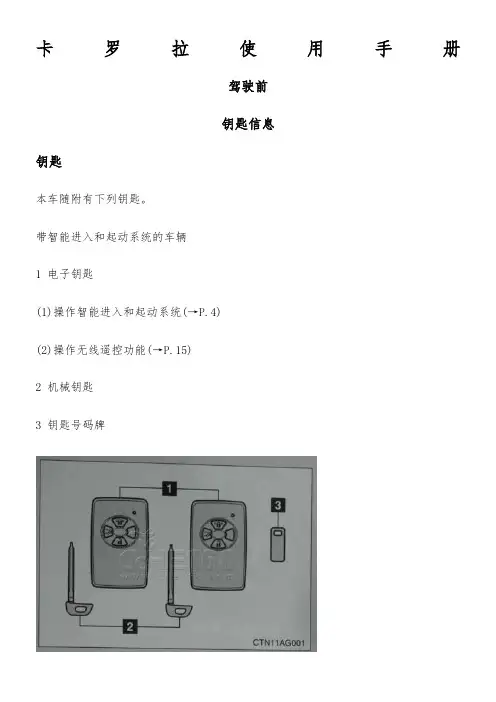
卡罗拉使用手册驾驶前钥匙信息钥匙本车随附有下列钥匙。
带智能进入和起动系统的车辆1 电子钥匙(1)操作智能进入和起动系统(→P.4)(2)操作无线遥控功能(→P.15)2 机械钥匙3 钥匙号码牌带智能进入和起动系统的车辆1 主钥匙操作无线遥控功能(→P.15)2 副钥匙3 钥匙号码牌使用机械钥匙(带智能进入和起动系统的车辆)取出机械钥匙。
使用机械钥匙后,将期放入电子钥匙内。
机械钥匙和电子钥匙应一同携带。
电子钥匙电池电量耗尽或进入功能不起作用时可使机械钥匙。
(→P.304)必须将车辆钥匙交给停车服务员时启动行李厢安全系统。
(→P.23)对于带智能进入和起动系统的车辆,务必取出机械随身保管,而仅将电子钥匙交给停车服务员。
对于不带智能进入和起动系统的车辆,将副钥匙交给停车服务员。
钥匙号码牌将号码牌放在安全的地方(如钱包内),不要放在车内。
如果丢失了钥匙,则您的丰田经销店、维修店或合格的技术人员均可利用钥匙号码牌制作新钥匙。
(→P.303)防止钥匙损坏1 切勿使钥匙受到猛烈碰撞或将其置于高温环境下(如阳光直射的地方),也勿使其受潮。
2 切勿使钥匙靠近电磁性材料或在其表面粘附任何可阻挡电磁波的材料。
打开、关闭和锁止车门智能进入和起动系统智能进入和起动系统(若装备)只要随身携带电子钥匙(如放在衣袋内),即可进行以下操作。
(驾驶员务必随身携带电子钥匙。
)1 锁止和解锁车门(→P.5)2 解锁行李厢(→P.5)3 起动发动机(→P.87)锁止和解锁车门(仅前车门把手)按下门锁按钮以锁止车门。
握住车门把手以解锁车门。
务必接触到把手内侧的传感器。
车门锁止后3秒内将无法解锁。
解锁行李厢按住按钮以解锁行李厢。
天线位置和有效作用范围天线位置1 车厢外部天线2 行李厢外部天线3 行李厢内部天线4 车厢内部天线有效作用范围(可以检测到电子钥匙的区域)1 锁止或解锁车门时电子钥匙在距任一前车门外把手约0.7m(米)的范围内时,可以对系统进行操作。
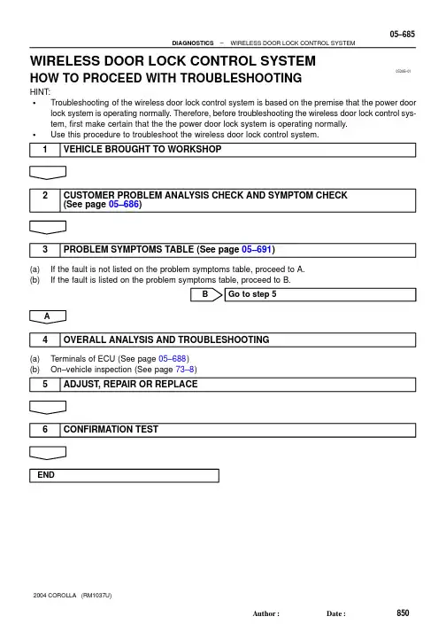
05DUB–01–DIAGNOSTICSWIRELESS DOOR LOCK CONTROL SYSTEM05–685850AuthorĂ:DateĂ:2004 COROLLA (RM1037U)WIRELESS DOOR LOCK CONTROL SYSTEMHOW TO PROCEED WITH TROUBLESHOOTINGHINT:STroubleshooting of the wireless door lock control system is based on the premise that the power door lock system is operating normally. Therefore, before troubleshooting the wireless door lock control sys-tem, first make certain that the the power door lock system is operating normally.SUse this procedure to troubleshoot the wireless door lock control system.1VEHICLE BROUGHT TO WORKSHOP2CUSTOMER PROBLEM ANALYSIS CHECK AND SYMPTOM CHECK (See page 05–686)3PROBLEM SYMPTOMS TABLE (See page 05–691)(a)If the fault is not listed on the problem symptoms table, proceed to A.(b)If the fault is listed on the problem symptoms table, proceed to B.BGo to step 5A4OVERALL ANALYSIS AND TROUBLESHOOTING(a)Terminals of ECU (See page 05–688)(b)On–vehicle inspection (See page 73–8)5ADJUST , REPAIR OR REPLACE6CONFIRMATION TESTEND056B8–07WIRELESS DOOR LOCK CONTROL SYSTEM Check SheetCustomer’s NameVINProduction Date Licence No.Odometer ReadingInspector’s Namekm miles//////Date Vehicle Brought inDate Problem First Occurred Frequency Problem OccursWeather Conditions When Problem OccurredDate Transmitter Battery Last ReplacedWeatherOutdoorTemperature PlaceConstant Sometimes ( times/per day, month)Once onlyFine Cloudy Rainy SnowyVarious/OthersHotWarm CoolCold (Approx. °C ( °F))EverywhereSpecific Locality ( )//P r o b l e m S y m p t o m sWhole wireless door lock control system does not operate.Only door unlock function does not operate.Only door lock function does not operate.Doors are locked by wireless door lock operation even when doors are open.Wireless door lock functions abnormally.Others05–686–DIAGNOSTICSWIRELESS DOOR LOCK CONTROL SYSTEM851AuthorĂ:DateĂ:2004 COROLLA (RM1037U)CUSTOMER PROBLEM ANALYSIS CHECK056BB–04B59374Front Door Lock LHRear Door Lock LHFront Door Courtesy Switch LHRear Door Lock RHRear Door Courtesy Switch LHDoor Control Receiver (Located inside the Roof Side Garnish Inner RH)TransmitterFront Door Lock RHUnlock Warning SwitchPower Window Master Switch (Door Lock Control Switch LH)Instrument Panel J/B (Integration Relay)Rear Door Courtesy Switch RHFront Door Courtesy Switch RHDoor Lock Control Switch RH–DIAGNOSTICSWIRELESS DOOR LOCK CONTROL SYSTEM05–687852AuthorĂ:DateĂ:2004 COROLLA (RM1037U)LOCATION056BC–02B57790I11Integration Relay Connector (Wire Harness Side)05–688–DIAGNOSTICSWIRELESS DOOR LOCK CONTROL SYSTEM853AuthorĂ:DateĂ:2004 COROLLA (RM1037U)TERMINALS OF ECU1.INSPECT INTEGRATION RELAY(a)Disconnect the connector from the integration relay.(b)Check the continuity between each terminal of the disconnected connector and the body ground, as shown in the illustration and table.Standard:If the result is not as specified, the vehicle’s side may malfunction.(c)Reconnect the connector and check the voltage between each terminal and the body ground, asshown in the illustration and table.Standard:If the result is not as specified, the integration relay may malfunction.B5937605–690–DIAGNOSTICSWIRELESS DOOR LOCK CONTROL SYSTEM855AuthorĂ:DateĂ:2004 COROLLA (RM1037U)(a)Disconnect the connectors IA, IB, ID, IF, IH and IJ of the instrument panel J/B.(b)Check the continuity between each terminal of the disconnected connectors and the body ground, as shown in the illustration and table.Standard:If the result is not as specified, the vehicle’s side may malfunction.(c)Reconnect the connectors and check the voltage between each terminal and the body ground, asshown in the illustration and table.Standard:If the result is not as specified, the integration relay or instrument panel J/B assembly may malfunction.056BD–07–DIAGNOSTICSWIRELESS DOOR LOCK CONTROL SYSTEM05–691856AuthorĂ:DateĂ:2004 COROLLA (RM1037U)PROBLEM SYMPTOMS TABLEB7040051+BGNDRDA PRG23L–R G–Y Instrument Panel J/BIntegration RelayIDID RDAPRG 78W–BBH108L–YJ9D3Door Control ReceiverW–BJ8A AJ/C48U1Unlock Warning Switch Assy Center J/B J6J/C KSWIJL–B164A 4A15L–B12W–B AIEToBattery05–692–DIAGNOSTICSWIRELESS DOOR LOCK CONTROL SYSTEM857AuthorĂ:DateĂ:2004 COROLLA (RM1037U)ONLY WIRELESS CONTROL FUNCTION DOES NOT OPERATE (PREPARE NEW OR NORMAL TRANSMITTER OF THE SAME TYPE VEHICLE)CIRCUIT DESCRIPTIONThe door control receiver receives a signal from the transmitter and sends this signal to the integration relay.Then, the integration relay controls door operation by sending a door LOCK/UNLOCK signal to each door lock motor.WIRING DIAGRAM05DUC–01–DIAGNOSTICSWIRELESS DOOR LOCK CONTROL SYSTEM05–693858AuthorĂ:DateĂ:2004 COROLLA (RM1037U)INSPECTION PROCEDUREHINT:The switch described in this text is a switch for transmitting signals which is built in the door control transmit-ter.1CHECK WIRELESS DOOR LOCK CONTROL FUNCTIONS (See page 73–8)NGGo to step 2OK NORMAL2REPLACE TRANSMITTER BATTERY WITH NORMAL ONE(a)After replacing the transmitter battery with a new or normal one, check that the doors can lock and unlock by using the transmitter LOCK/UNLOCK switch.NGGo to step 3OKREPLACE TRANSMITTER BATTERY3CHECK WIRELESS DOOR LOCK CONTROL FUNCTIONS(a)Check if UNLOCK–LOCK operates in standard operation.NOTICE:Standardized test procedure: Press the transmitter switch for 1 second, directing the beam to driver side door outside handle from a distance of 1 m (39.4 in.). The transmitter should be pointed directly at the door handle, i.e at 90_ angle to the vehicle body.NGREPLACE DOOR CONTROL TRANSMITTEROK4CONFIRM ROOM LAMP ON(a)Check that the wireless door lock buzzer sounds.B52341Room Lamp OFFa: 0.25 sec.b: 0.5 sec.ON ab05–694–DIAGNOSTICSWIRELESS DOOR LOCK CONTROL SYSTEM859AuthorĂ:DateĂ:2004 COROLLA (RM1037U)5SWITCH TO SELF–DIAGNOSTIC MODE(a)Switch to self–diagnostic mode by operating the ignition key cylinder.(1)Put the vehicle under the vehicle’s initial condition (See page 73–8), insert the key into the igni-tion key cylinder and remove it.(2)Within 5 seconds after the key is removed (step 1), insert the key into the ignition key cylinder(ignition key OFF) and perform the following once: Turn the ignition switch to ON and return it to OFF.(3)Within 30 seconds after the ignition switch is returned to OFF (step 2), perform the following 9times: Turn the ignition switch to ON and return it to OFF.NOTICE:If operation has failed, the system will return to normal mode.HINT:S Turning the ignition switch ON after step 3 has been completed will end self–diagnostic mode.S Do not lock or unlock doors during self–diagnostic mode.(b)Check that the system has switched to self–diagnostic mode by the blinking frequency of the room lamp.NG Go to step 9OKNormal wave of UNLOCK switch is receivedNo diagnosis outputsRoom Light OutputONOFFT1: 0.25 sec.T2: 0.5 sec.Wave ReceivingRoom Light OutputONOFFRoom Light OutputOFFT1T1T1T2Normal wave of LOCK switch is receivedRoom Light OutputONOFFT1T2Unmatching recognition code6CHECK BY SELF–DIAGNOSTIC MODE(a)Inspect the diagnosis outputs when the door control transmitter switch is held down (The diagnosis outputs can be checked with the outputs of the room lamp).HINT:S In the case of a reception of the normal wave of the door LOCK and UNLOCK switch (room lamp blink-ing), go to step A.S In the case of an unmatching recognition code (room lamp ON), go to step B.SIn the case of no diagnosis outputs (room lamp OFF), go to step C.A Go to step 16CGo to step 8B7REGISTER RECOGNITION CODE(a)Check that the system can switch to rewrite mode or add mode and whether a recognition code can be registered.NGGo to step 15OK NORMAL8CHECK RESPONSE OF DOOR CONTROL RECEIVER(a)When a new or normal door control transmitter switch for the same type vehicle is held down, checkthat a diagnosis of unmatching recognition code is output.NG Go to step 12OKREPLACE DOOR CONTROL TRANSMITTER9CONFIRM INPUT METHOD OF SELF–DIAGNOSTIC MODE(a)When the method for switching the system to self–diagnostic mode works, proceed to A.(b)When the method for switching the system to self–diagnostic mode does not work, proceed to B.B Go to step 5A10INSPECT UNLOCK WARNING SWITCH ASSYPushedB51903U1IJ21Instrument Panel J/B (Wire Harness Side)Door Control Receiver (Wire Harness Side)CHECK WIRE HARNESS (DOOR CONTROL RECEIVERB51174Door Control ReceiverD3B59377Instrument Panel J/B(Wire Harness Side)Door Control Receiver (Wire Harness Side)IDD313CHECK DOOR CONTROL RECEIVER(a)Reconnect the connector to the door control receiver, and check the voltage between the terminal and the body ground, as shown in the illustration and table.Standard:NGGo to step 15OK14CHECK WIRE HARNESS (DOOR CONTROL RECEIVER ⇔ INSTRUMENT PANEL J/B) (DOOR CONTROL RECEIVER OR INSTRUMENT PANEL J/B ⇔ BODY GROUND)OK15REPLACE DOOR CONTROL RECEIVER WITH NORMAL ONENG Go to step 16OKREPLACE DOOR CONTROL RECEIVER16REPLACE INTEGRATION RELAY WITH NORMAL ONENG REPLACE INSTRUMENT PANEL JUNCTIONBLOCK ASSYOKREPLACE INTEGRATION RELAY。
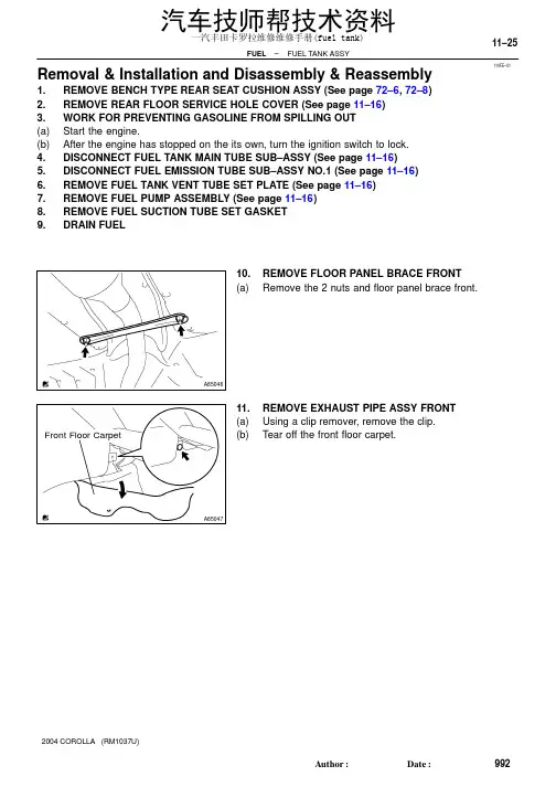
110FE–01A65046A65047Front Floor Carpet –FUEL FUEL TANK ASSY11–25992AuthorĂ:DateĂ:2004 COROLLA (RM1037U)Removal & Installation and Disassembly & Reassembly1.REMOVE BENCH TYPE REAR SEAT CUSHION ASSY (See page 72–6, 72–8)2.REMOVE REAR FLOOR SERVICE HOLE COVER (See page 11–16)3.WORK FOR PREVENTING GASOLINE FROM SPILLING OUT(a)Start the engine.(b)After the engine has stopped on the its own, turn the ignition switch to lock.4.DISCONNECT FUEL TANK MAIN TUBE SUB–ASSY (See page 11–16)5.DISCONNECT FUEL EMISSION TUBE SUB–ASSY NO.1 (See page 11–16)6.REMOVE FUEL TANK VENT TUBE SET PLATE (See page 11–16)7.REMOVE FUEL PUMP ASSEMBLY (See page 11–16)8.REMOVE FUEL SUCTION TUBE SET GASKET9.DRAIN FUEL10.REMOVE FLOOR PANEL BRACE FRONT(a)Remove the 2 nuts and floor panel brace front.11.REMOVE EXHAUST PIPE ASSY FRONT(a)Using a clip remover, remove the clip.(b)Tear off the front floor carpet.汽车技师帮技术资料一汽丰田卡罗拉维修维修手册(fuel tank)A65706A65049A6505011–26–FUEL FUEL TANK ASSY993AuthorĂ:DateĂ:2004 COROLLA (RM1037U)(c)Disconnect the oxygen sensor connector.(d)Remove the 2 exhaust pipe supports.(e)Remove the 4 bolts, 4 compression springs and exhaustpipe.12.REMOVE FUEL TANK PROTECTOR NO.1(a)Remove the 5 bolts and fuel tank protector.13.SEPARATE PARKING BRAKE CABLE ASSY NO.2(a)Remove the 2 installing bolts of the parking brake cable.汽车技师帮技术资料一汽丰田卡罗拉维修维修手册(fuel tank)A65051A65052A66709Nylon Tube Fuel TubeConnector Clip Pipe O–ring Fuel Tube Connector A65054A65055–FUEL FUEL TANK ASSY 11–27994AuthorĂ:DateĂ:2004 COROLLA (RM1037U)14.SEPARATE PARKING BRAKE CABLE ASSY NO.3(a)Remove the 2 installing bolts of the parking brake cable.15.DISCONNECT FUEL TANK MAIN TUBE SUB–ASSY (a)Pinch the fuel tube connector clip, and remove the fuel tube connector clip.(b)Pull out the fuel tank main tube.NOTICE:S Check if there is any dirt like mud around the fuel tube connector before this work and clean the dirt away.S Be careful of dirt like mud because the fuel tube con-nector has an O–ring to seal the fuel tube connector and pipe.S Do not use any tool in this work.S Do not bend or twist the nylon tube by force.S After disconnecting, cover the fuel tube connector with a vinyl bag.S When the fuel tube connector and pipe are stuck,pinch the fuel tank main tube between fingers, and turn it carefully to free and then disconnect the fuel tank main tube.16.DISCONNECT FUEL TANK INLET PIPE FUEL HOSE (a)Disconnect the fuel tank inlet filler pipe hose from the fuel tank.17.DISCONNECT FUEL TANK BREATHER HOSE (a)Disconnect the fuel tank breather hose from the fuel tank.汽车技师帮技术资料一汽丰田卡罗拉维修维修手册(fuel tank)A65056Push Pinch A A PinchA65057A65058A65059Nylon Tube Fuel TubeConnector ClipPipe O–ring Fuel Tube Connector A6506011–28–FUEL FUEL TANK ASSY 995AuthorĂ:DateĂ:2004 COROLLA (RM1037U)18.DISCONNECT FUEL TANK VENT HOSE (a)Disconnect the fuel tank bent hose from the charcoal can-ister.(1)Push the connector deep inside.(2)Pinch portion A.(3)Pull out the connector.19.DISCONNECT VALVE TO FUEL FILLER PIPE HOSE (a)Disconnect the valve to fuel filler pipe hose from the fuel tank inlet pipe.20.DISCONNECT FUEL EMISSION TUBE SUB–ASSY NO.1(a)Pinch the fuel tube connector clip and then pull out the fuel emission tube.NOTICE:S Check if there is any dirt like mud around the fuel tube connector before this work and clean the dirt away.S Be careful of dirt like mud because the fuel tube con-nector has an O–ring to seal the fuel tube connector and pipe.S Do not use any tool in this work.S Do not bend or twist the nylon tube by force.S After disconnecting, cover the fuel tube connector with a vinyl bag.S When the fuel tube connector and pipe are stuck,pinch the fuel emission tube between fingers, and turn it carefully to free and then disconnect the fuel emission tube.21.REMOVE FUEL TANK ASSY (a)Set a mission jack to the fuel tank.(b)Remove the 4 bolts, 2 fuel tank bands and fuel tank.汽车技师帮技术资料一汽丰田卡罗拉维修维修手册(fuel tank)A65061A65062A65063A65064A60576Nylon TubeFuel TubeConnector ClipPipe O–ring Fuel TubeConnector –FUEL FUEL TANK ASSY 11–29996AuthorĂ:DateĂ:2004 COROLLA (RM1037U)22.REMOVE FUEL TANK MAIN TUBE SUB–ASSY (a)Remove the fuel tank main tube from the fuel tube clamp and bracket.23.REMOVE FUEL TUBE CLAMP NO.4(a)Remove the bolt and fuel tank clamp.24.REMOVE FUEL TUBE BRACKET (a)Remove the fuel tube bracket from the fuel tank.25.REMOVE FUEL EMISSION TUBE SUB–ASSY NO.1(a)Pinch the fuel tube connector clip and then pull out the fuel emission tube.NOTICE:S Check if there is any dirt like mud around the fuel tube connector before this work and clean the dirt away.S Be careful of dirt like mud because the fuel tube con-nector has an O–ring to seal the fuel tube connector and pipe.S Do not use any tool in this work.S Do not bend or twist the nylon tube by force.S After disconnecting, cover the fuel tube connector with a vinyl bag.S When the fuel tube connector and pipe are stuck,pinch the fuel emission tube between fingers, and turn it carefully to free and then disconnect the fuel emission tube.汽车技师帮技术资料一汽丰田卡罗拉维修维修手册(fuel tank)A65065A65066A65067Clip Remover Gasket A6506811–30–FUEL FUEL TANK ASSY 997AuthorĂ:DateĂ:2004 COROLLA (RM1037U)26.REMOVE FUEL TUBE CLAMP NO.2(a)Remove the fuel tube clamp from the fuel tank.27.REMOVE CHECK VALVE PROTECTOR (a)Using a screwdriver, unlock the claw, and remove the check valve protector by turning it counter clockwise.28.REMOVE FUEL TANK INLET VALVE ASSY (a)Insert a clip remover between the fuel tank inlet valve and gasket, remove the fuel tank inlet valve by gradually pushing it upward.NOTICE:S Work accurately to maintain the sealing performance of the fuel tank inlet valve, since it is made from resin.It is easy to damage by removing and installing forci-bly.S Be sure to install a new fuel tank inlet valve and gas-ket.29.REMOVE CHECK VALVE GASKET (a)Remove the gasket from the fuel tank inlet valve.汽车技师帮技术资料一汽丰田卡罗拉维修维修手册(fuel tank)A65069A65069A65070A65071Apply a light coatof oil–FUEL FUEL TANK ASSY 11–31998AuthorĂ:DateĂ:2004 COROLLA (RM1037U)30.REMOVE FUEL TANK CUSHION NO.1(a)Remove the 7 fuel tank cushions from the fuel tank.31.INSTALL FUEL TANK CUSHION NO.1(a)Install the 7 new fuel tank cushions to the fuel tank.32.INSTALL CHECK VALVE GASKET (a)Install a new gasket to the fuel tank.33.INSTALL FUEL TANK INLET VALVE ASSY (a)Apply a light coat of oil around the fuel tank inlet valve asshown in the illustration, and insert it into the fuel tankwithout force.NOTICE:Be careful not to drop the gasket into the fuel tank.34.INSTALL FUEL EMISSION TUBE SUB–ASSY NO.1(a)Push in the fuel tube connector to the pipe until fuel tube connector makes ”click” sound.NOTICE:S Check if there is any damage or foreign objects on the connected part.S After connecting, check if the fuel tube connector and pipe are securely connected by pullingthem.35.INSTALL FUEL TUBE CLAMP NO.4(a)Install the fuel tube clamp with the bolt.Torque: 6.0 N ⋅m (61 kgf ⋅cm, 53 in.⋅lbf)汽车技师帮技术资料一汽丰田卡罗拉维修维修手册(fuel tank)A51891Tail Pipe Side Gasket –FUEL FUEL TANK ASSY 11–331000AuthorĂ:DateĂ:2004 COROLLA (RM1037U)(c)Install a new gasket on the exhaust pipe (rear side).(d)Install the exhaust pipe with the 4 compression springsand 4 bolts.Torque: 43 N ⋅m (440 kgf ⋅cm, 32 ft ⋅lbf)(e)Install the 2 exhaust pipe supports.(f)Connect the oxygen sensor connector.(g)Install the font floor carpet with a clip.43.INSTALL FLOOR PANEL BRACE FRONT(a)Install the floor panel brace front with the 2 nuts.Torque: 30 N ⋅m (302 kgf ⋅cm, 22 ft ⋅lbf)44.INSTALL FUEL SUCTION TUBE SET GASKET (See page 11–16)45.INSTALL FUEL PUMP ASSEMBLY (See page 11–16)46.INSTALL FUEL TANK VENT TUBE SET PLATE (See page 11–16)47.CONNECT FUEL EMISSION TUBE SUB–ASSY NO.1 (See page 11–16)48.CONNECT FUEL TANK MAIN TUBE SUB–ASSY (See page 11–16)49.CHECK FUEL LEAK (See page 11–1)50.CHECK EXHAUST GAS LEAK51.INSTALL REAR FLOOR SERVICE HOLE COVER (See page 11–16)52.INSTALL BENCH TYPE REAR SEAT CUSHION ASSY (See page 72–6, 72–8)汽车技师帮技术资料一汽丰田卡罗拉维修维修手册(fuel tank)。
前言此电路图手册提供了COROLLA电气系统的信息。
适用车型: ZRE151, 152系列本手册中未予以阐述的上述车型的维修规范和修理步骤,敬请参考下列手册:手册名称出版号• COROLLA修理手册RM05N0EC• COROLLA新车特征NM05N0EC本手册中收录的所有信息是手册出版时最新的车辆信息。
但是,规格和步骤可能出现变化,恕不另行通知。
丰田汽车公司小心处理辅助约束系统零部件 (拆卸、安装或检查等) 时,必须遵守上述修理手册列出的说明,避免引发事故和辅助约束系统出现故障。
©2007 丰田汽车公司版权所有。
未经丰田汽车公司书面许可,不得转载或复印本手册的部分或全部内容。
123121718205271328336344366370COROLLA 电路图导言. . . . . . . . . . . . . . . . . . . . . . . . . . . . . . . . . . . . A . . . . 如何使用本手册. . . . . . . . . . . . . . . . . . . . . . . . . . . B . . . . 故障排除 . . . . . . . . . . . . . . . . . . . . . . . . . . . . . . . . C . . . . 缩写. . . . . . . . . . . . . . . . . . . . . . . . . . . . . . . . . . . . D . . . . 术语和符号表. . . . . . . . . . . . . . . . . . . . . . . . . . . . . E . . . . 继电器位置分布图. . . . . . . . . . . . . . . . . . . . . . . . . F . . . . 电路图. . . . . . . . . . . . . . . . . . . . . . . . . . . . . . . . . . G . . . . 系统电路 . . . . . . . . . . . . . . . . . . . . . . . . . . . . . . . . H . . . . 搭铁点. . . . . . . . . . . . . . . . . . . . . . . . . . . . . . . . . . I . . . . 电源 (电流流程图) . . . . . . . . . . . . . . . . . . . . . . . . J . . . . 连接器表 . . . . . . . . . . . . . . . . . . . . . . . . . . . . . . . . K . . . . 连接器零件号. . . . . . . . . . . . . . . . . . . . . . . . . . . . . L . . . . 总电路图 . . . . . . . . . . . . . . . . . . . . . . . . . . . . . . . . M . . . .页码章节代码A 导言2本手册由以下13个章节组成: 代码章节简述A 索引本手册内容的索引。
卡罗拉维修手册-车门卡罗拉维修手册-车门
章节一、车门维修概述
1.1 车门结构及组成部件
1.2 车门维修基础知识
1.2.1 车门故障排除常见步骤
1.2.2 使用的工具和设备
章节二、车门开闭系统维修
2.1 车门锁系统维修
2.1.1 车门锁组成及工作原理
2.1.2 车门锁常见故障及排除方法
2.2 车门开关维修
2.2.1 车门开关类型及工作原理
2.2.2 车门开关常见故障及排除方法
2.3 车门电动窗维修
2.3.1 车门电动窗组成及工作原理
2.3.2 车门电动窗常见故障及排除方法章节三、车门外饰部件维修
3.1 车门把手维修
3.1.1 车门把手类型及拆卸方法
3.1.2 车门把手常见故障及修理方案3.2 车门玻璃维修
3.2.1 车门玻璃组成及拆卸方法
3.2.2 车门玻璃常见故障及修理方案3.3 车门镜子维修
3.3.1 车门镜子类型及拆卸方法
3.3.2 车门镜子常见故障及修理方案章节四、车门内饰部件维修
4.1 车门板拆卸和安装
4.2 车门防撞垫维修
4.3 车门内饰件维修
章节五、保养及注意事项
5.1 车门维护保养
5.2 安全注意事项
附件:
附件一、车门维修工具清单
附件二、车门电路原理图
附件三、车门组件拆解示意图
法律名词及注释:
1:车辆保修条款:指车门维修所适用的保修政策和细则。
2:汽车维修法规:指针对汽车维修行业制定的法律法规文件。
3:零件替换:指车门维修中可能涉及的需要更换的零部件。
本文档涉及附件。
本文所涉及的法律名词及注释。
丰田卡罗拉的维修保养手册1、卡罗拉手动挡汽车踩离合器时易发出声响:原因是离合器踏板轴套缺油,可以与经销商联系,在轴套上加油。
2、后排车门从内侧有时无法打开:原因是儿童保护锁关闭,打开即可。
3、客户实际使用油耗与厂家提供的理论油耗有差别:原因是厂家提供理论油耗值是汽车在平坦路面匀速行驶时的耗油值,而用户实际驾驶时制动、转弯、承载人数等因素不同,造成了实际耗油量也有所差别。
一般情况下制动一次耗油量可行驶2—3公里。
车上承载重量增加50公斤,每公里多耗油0.5公升。
等人3分钟以上耗油明显增加,建议熄火等候。
4、汽油滤芯堵塞、喷油嘴积炭过多:原因是加注燃油纯净度低,污染节气门,使得汽油滤芯堵塞、喷油嘴积炭过多。
建议用户到正规加油站加油,并加注出厂时规定标号的燃油,一般情况下,加注95#以上燃油。
保养手册1、清洗车漆表面清洁和保护车辆内饰外饰的时候,请您注意:请勿使用有机清洁剂(如苯或汽油)。
2、清洗风挡玻璃从风挡玻璃处提起刮水器臂时,应先向上拉起驾驶员侧刮水器臂。
再以同样方式拉起乘员侧刮水器臂。
将刮水器臂恢复至其初始位置时,首先从乘员侧进行操作。
3、清洗车灯表面清洗时应小心,请勿使用有机清洗剂或硬刷进行清洗。
否则可能损坏车灯表面。
请勿在车灯表面打蜡,车蜡可能会损伤车灯罩。
4、清洗车窗内侧清洁玻璃内侧不要用玻璃清洁剂,因为其会导致后车窗除雾器电热丝或天线损坏。
应将布用温水浸湿,沿着与电热丝或天线平行的方向轻轻擦拭。
清洗内饰使用真空吸尘器清除污物和灰尘,将布用温水浸湿后,擦洗脏污的表面。
特别注意为了延长车辆的寿命,在新车磨合期间,请您注意:在最初300km(公里)内,请避免紧急停车。
在最初1000km(公里)内,避免以极高车速驾驶,避免突然加速,请勿持续在低速挡行驶。
挂档困难:离合器故障排除方法一、故障现象: 发动机怠速运转时,离合器踏板虽已踩到底,但挂档困难,变速齿轮有撞击声。
勉强挂上档后,尚未放松离合器踏板,汽车已行使或熄火。
青海交通科技2019—5丰田卡罗拉车门损伤修复吴洪福(海东市乐都区畜牧兽医站海东810700)摘要当前,随着我国汽车产业的发展,我国汽车的保有量都在不断增长,因而汽车车身修复也成为一项必不可少的行业。
本文介绍了丰田卡罗拉汽车的车身结构、组成以及特点,以车门面板的拉拔修复为例,详细介绍了其修复流程,并介绍了维修过程中所使用的设备和工具。
关键词卡罗拉车门面板修复(Haidong ledu district animal husbandry veterinary station%Haidong810700%China) Abstract At present,with the developmeni of Chinas automobile industry%the cay ownership in China is increasing%so the automobile body repair has become an indmpensable industry.Thm paper introduces the structure, composition and chaacteasticc of the body o f Toyotr Carola.Taking tre doawing oepair of the door pand as an example,the repaio process is introduced in detaii,and tre equipment and tools used in tre maintenance process are also intoduced.Key wordt Corolla;Door Panels;repair众所周知,车辆在日常生活中难免会出现刮擦或碰撞,而在这些事故中,小损伤占了整体损伤的绝大部分。
丰田卡罗拉汽车作为一种家用型汽车,受到群众广泛的欢迎。