3GPP_Channel Model 25996-a00
- 格式:pdf
- 大小:1.41 MB
- 文档页数:40
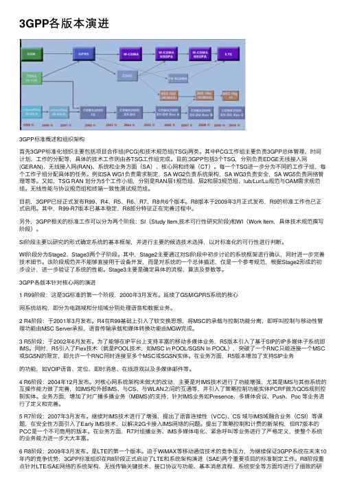
3GPP各版本演进3GPP标准概述和组织架构⾸先3GPP标准化组织主要包括项⽬合作组(PCG)和技术规范组(TSG)两类。
其中PCG⼯作组主要负责3GPP总体管理、时间计划、⼯作的分配等,具体的技术⼯作则由各TSG⼯作组完成。
⽬前,3GPP包括3个TSG,分别负责EDGE⽆线接⼊⽹(GERAN)、⽆线接⼊⽹(RAN)、系统和业务⽅⾯(SA)、核⼼⽹和终端(CT)。
每⼀个TSG进⼀步分为不同的⼯作⼦组,每个⼯作⼦组分配具体的任务。
例如SA WG1负责需求制定,SA WG2负责系统架构,SA WG3负责安全,SA WG5负责⽹络管理等等。
⼜如,TSG RAN 划分为5个⼯作⼩组,分别是RAN层1规范组、层2和层3规范组、lub/Lur/Lu规范与OAM需求规范组。
⽆线性能与协议规范组和终端⼀致性测试规范组。
⽬前,3GPP已经正式发布R99、R4、R5、R6、R7、R8共6个版本。
R8版本于2009年3⽉正式发布,R9的标准⼯作也已正式启⽤。
其中,R99-R7版本已基本稳定,R8部分特征正在完善过程中。
另外,3GPP相关的标准⼯作可以分为两个阶段:SI(Study Item,技术可⾏性研究阶段)和WI(Work Item,具体技术规范撰写阶段)。
SI阶段主要以研究的形式确定系统的基本框架,并进⾏主要的候选技术选择,以对标准化的可⾏性进⾏判断。
WI阶段分为Stage2、Stage3两个⼦阶段。
其中,Stage2主要通过对SI阶段中初步讨论的系统框架进⾏确认,同时进⼀步完善技术细节。
该阶段规范并不能够直接⽤于设备开发,⽽是对系统的⼀个总体描述,仅是⼀个参考规范,根据Stage2形成的初步设计,进⼀步验证了系统的性能。
Stage3主要是确定具体的流程、算法及参数等。
3GPP各版本针对核⼼⽹的演进1 R99阶段:这是3G标准的第⼀个阶段,2000年3⽉发布。
延续了GSM/GPRS系统的核⼼⽹系统结构,即分为电路域和分组域分别处理语⾳和数据业务。


3GPP标准查找指南-3GPP介绍1.概述3GPP是积极倡导UMTS为主的第三代标准化组织,成立于1998年12月,是一个协作协议。
这一协作协议将许多电信标准实体(组织伙伴)连接到了一起。
1998年12月,《第三代伙伴计划协议》的签署标志了3GPP正式成立。
3GPP最初的工作范围是为第三代移动系统制定全球适用技术规范和技术报告。
第三代移动系统基于的是发展的GSM核心网络和他们所支持的无线接入技术。
随后3GPP的工作范围得到了改进,包括为移动通信(GSM)技术规范和技术报告包括发展的无线接入技术(包括GPRS和EDGE)维护和制定全球系统。
目前欧洲ETSI,美国T1,日本TTC,ARIB和韩国TTA以及我国CCSA都作为组织伙伴(OP)积极参与了3GPP的各项活动。
2.3GPP组织结构3GPP由项目协调组(PCG)和技术规范组(TSGs)组成,如需要,各技术规范组可建立工作组。
3.3GPP的研究领域(1)UTRAN(包括FDD和TDD模式);(2)3GPP核心网络(GSM发展而来的第3代网络能力。
这些能力包括移动管理、全球漫游、相关互联网协议的使用);(3)接入到以上网络的终端;(4)系统和服务方面。
全球移动通信系统包括:GSM发展的无线接入技术(通用分组无线服务(GPRS)和GSM发展的增强数据率(EDGE))。
4.TSG SA(业务和系统结构)业务和系统结构(SA)它具体负责3GPP所承担工作的技术合作,并且负责系统的整体结构和系统的完整性。
应该指出的是,每个TSG都对它所涉及的规范有推进、批准和维护的责任。
SA1:业务能力a.业务和特征要求的定义b.业务能力和蜂窝、固定、无绳应用的业务结构的发展SA2:结构a.整个结构的定义、演进和维护,包括对一些特别子系统(UTRAN,GERAN,核心网,终端,SIM/USIM)的功能分配,关键信息流的识别b.在和其它TSG的合作中,定义所要求的业务,业务能力和由不同子系统提供的承载能力,包括使用分组和电路交换网的业务质量(QoS)安全框架的定义,,整个系统安全方面的评论SA3:安全框架的定义SA4:CODEC 方面a.定义端到端传输的原则b.相关规范的定义、推进和维护网管::网管结构以及具体的信息模型SA5网管5.TSG CT(核心网与终端)核心网TSG核心网(TSG-CN)负责基于3GPP规范系统的核心网络部分的规范。

-精品文档-前言本通信标准参考性技术文件主要收集了与定义IMT-DS FDD(WCDMA)系统的目标和系统结构的基本文档相关的术语、定义和缩略语。
本文基于3GPP制订的Release-99(2000年9月份版本)技术规范,具体对应于TS 25.990 V3.0.0。
本参考性技术文件由信息产业部电信研究院提出。
本参考性技术文件由信息产业部电信研究院归口。
本参考性技术文件起草单位:信息产业部电信传输研究所本参考性技术文件主要起草人:徐京皓徐菲卓天真续合元盛蕾吴伟本参考性技术文件2001年1月首次发布。
本参考性技术文件委托无线通信标准研究组负责解释。
通信标准参考性技术文件IMT-DS FDD(WCDMA)系统无线接口物理层技术规范:名语术语IMT-DS FDD(WCDMA) System Radio Interface Technical Specification: Vocabulary1 范围本通信标准参考性技术文件介绍了与定义IMT-DS FDD(WCDMA)系统的目标和系统结构的基本文档相关的术语,定义和缩略语。
这篇文档也为以后的技术规范的工作提供了一个工具,以便于理解。
在这篇文档中所给出的术语,定义和缩略语或者是从现在的文档(ETSI,ITU或其它)引入的,或者是在需要精确的词汇时新创造出来的。
2 引用标准下列标准所包含的条文,通过在本标准中引用而成为本文件的条文。
本文件出版时,所示版本均为有效。
所有标准都会被修订,使用本文件的各方应探讨使用下列标准最新版本的可能性。
3 与UTRA相关的术语和定义AAcceptable Cell可接受的小区:是指UE可以驻留并进行紧急呼叫的小区。
它必须满足特定的条件。
Access Stratum;接入层;Access Stratum SDU (Service Data Unit)接入层SDU(业务数据单元):在核心网或UE的接入层SAP(业务接入点)上传送的数据单元。

Javier GozalvezNew 3GPP Standard for IoTInternet of Thingsmajor milestone was achieved inthe Third-Generation Partner-ship Project’s (3GPP’s) Radio AccessNetwork Plenary Meeting 69 with thedecision to standardize the narrow-band (NB) Internet of Things (IoT), anew NB radio technology to addressthe requirements of the IoT. The newtechnology will provide improved in-door coverage, support of a massivenumber of low-throughput devices,low delay sensitivity, ultralow devicecost, low device power consump-tion, and optimized network archi-tecture. The technology can bedeployed in-band, utilizing resourceblocks within a normal long-termevolution (L TE) carrier, or in the un-used resource blocks within an L TEcarrier’s guard-band, or stand alonefor deployments in dedicated spec-trum. The NB-IoT is also particularlysuitable for the refarming of GlobalSystem for Mobile Communications(GSM) channels.Ericsson, AT&T, and Altair dem-onstrated over ten years of batterylife using LTE power-saving mode(PSM) on a commercial LTE IoT chipset platform. The demonstrationruns on Ericsson networks and Al-tair’s FourGee-1160 Cat-1 chip set fea-turing ultralow power consumption.Long-term battery life has becomea prerequisite for a vast number ofIoT applications. PSM is an EricssonEvolved Packet Core (EPC) featurebased on 3GPP (Release 12) for bothGSM and LTE networks. The featureis able to dramatically extend I oTdevice battery life up to ten yearsor more for common use cases andtraffic profiles. This capability isdefined for both LTE and GSM tech-nologies and lets devices enter anew deep-sleep mode—for hours oreven days at a time—and only wakeup when needed.Ericsson, Sony Mobile, and SKTelecom conducted lab testing ofthe key functionalities of LTE deviceCategory 0 and Category M (Machine-Type Communication). LTE Category0 has been standardized in the3GPP LTE Release 12 and is the firstdevice category specifically target-ing reduced complexity and, thus,reduced cost for the IoT. LTE CategoryM is a key theme in LTE Release 13,representing further cost savings andimproving battery lifetime. Wearabledevices and related applications wereselected for the user scenarios beingtested and trialed. The wearabledevice test use cases are focused onconsumer lifestyle and wellness ap-plications enabled through multiplesensors providing accelerometer,identification, pulse meter, and globalpositioning system functionality.Orange and Ericsson announceda trial of optimized, low-cost, low-complexity devices and enhancednetwork capabilities for cellular IoTover GSM and LTE. What the compa-nies claim will be the world’s first ex-tended coverage (EC) GSM trial willbe conducted in France using the900-MHz band, with the aim of en-hancing device reachability by up to20 dB, or a sevenfold improvementin the range of low-rate applications.This further extends the dominantglobal coverage of GSM in Europeand Africa to reach challenging lo-cations, such as deep indoor base-ments, where many smart metersare installed, or remote areas inwhich sensors are deployed for agri-culture or infrastructure monitoringuse cases. I n addition, EC-GSM willreduce device complexity and, thus,lower costs, enabling large-scale IoTdeployments. In parallel, the compa-nies will carry, in partnership withSequans, what they believe is theworld’s first LTE IoT trial using low-cost, low-complexity devices withone receive antenna (instead of two),and half-duplex frequency divisionduplex (FDD). This simplifies thedevice hardware architecture andreduces expensive duplex filters, al-lowing for a 60% cost reduction incomparison with the existing LTECategory 4. Ericsson will also dem-onstrate, together with Sequans,energy efficiency over GSM and LTEnetworks with the PSM technology.The PSM feature is applicable toboth GSM and LTE and supportedby EPC.Digital Object Identifier 10.1109/MVT.2015.2512358Date of publication: 24 February 2016AEricsson, MyOmega System Tech-nologies, Intel, and Telenor Connex-ion have partnered to build what they claim is the world’s first end-to-end site implementation of secure oT connectivity service for wine-makers. The service will enable wine-makers to collect data on air and soil humidity and temperature, as well as solar intensity, using IoT sensors and ntel-based oT gateways con-nected to a cloud service. The data can be used to perform a predictive analysis and to support resource management and real-time remote monitoring. Ericsson’s secure I oT service is based on the Ericsson De-vice Connection Platform integrated with the Authentication Federation Gateway. Built on the 3GPP standard Generic Bootstrapping Architecture for LTE, the implementation features what Ericsson claims is the world’s first end-to-end security and authen-tication capabilities for transferring sensor data to the cloud for process-ing and analysis.Berg I nsight estimates that LTE will be the leading technology for cellular I oT devices in 2019. The company estimates that global ship-ments of cellular oT devices will grow at a compound annual growth rate (CAGR) of 20.1% to reach 239.7 million units in 2020.Gartner estimates that 6.4 bil-lion connected things will be in use worldwide in 2016, which repre-sents an increase of 30% from 2015. This figure will reach 20.8 billion by 2020. The firm expects that IoT will support total services spending of US$235 billion in 2016, which repre-sents an increase of 22% from 2015. Fifth GenerationThe Radiocommunication Assembly of the International Telecommunica-tion Union (ITU) has endorsed a res-olution that establishes the road map for the development of fifth-generation (5G) mobile and the term that will apply to it: “I nternational Mobile Telecommunications (I MT) 2020.” The overall vision for the 5G systems, along with the goals, pro-cess, and time line for its develop-ment, is now in place. The detailedtechnical performance requirementsfor the radio systems to support 5Gwill be developed, in close collabo-ration with industry and nationaland regional standards organiza-tions, following the stringent timelines defined by ITU. New demands,including applications requiringvery high-data-rate communica-tions, many more devices withdiverse service requirements, betterquality of user experience, and bet-ter affordability, will require anincreasing number of innovativesolutions. Low-latency and high-reli-ability communication are perceivedas an enabler for the future develop-ment of new applications in healthcare, safety, business, entertain-ment, and other sectors.NTT DOCOMO, I nc., announcedthat a 5G trial it conducted withNokia Networks at the RoppongiHills high-rise complex in Tokyo, Ja-pan, achieved ultrahigh-speed datatransmission in excess of 2 Gb/s.The trial used millimeter-wave-length signals with an extremelyhigh frequency of 70 GHz, a key de-velopment for the eventual commer-cial use of 5G wireless technology inactual-use environments. Accordingto the company, to date, no test hadachieved a 5G data transmission ina commercial complex, such as ashopping mall, due to problems withbase stations being out of line ofsight and diffused reflections caus-ing the attenuation of highly direc-tional millimeter signals. This time,however, the trial was successfulbecause of the use of two technolo-gies: 1) beamforming, which focusesradio waves in a specific direction,and 2) beam tracking to controlbeam direction according to the mo-bile device’s location. n addition,in a separate trial that DOCOMOconducted with Samsung Electron-ics in Suwon-city, South Korea, amaximum data-receiving speed ofmore than 2.5 Gb/s was achievedin a vehicle travelling with a speedof 60 km/h. The trial used a 28-GHzhigh-frequency signal in combina-tion with beamforming with a highnumber of antenna elements andbeam tracking.DOCOMO conducted other tri-als recently in collaboration withvendors: DOCOMO and Ericssonverified the feasibility of a mas-sive multiple-input, multiple-output(MI MO) technology by achieving areal-time data-receiving speed ofmore than 10 Gb/s using Ericsson5G radio prototypes with a 15-GHzfrequency band. DOCOMO and Fu-jitsu confirmed a multi-base-stationcooperative transmission system byachieving a data-receiving speed ofover 11 Gb/s in a total of four mobiledevices with a 4.6-GHz signal. Anoutdoor data-transmission trial con-ducted by DOCOMO, DOCOMO Bei-jing Communications Laboratories,and Huawei Technologies achieveda multiuser (MU) MI MO transmis-sion of 43.9 b/s/Hz/cell, which was3.6-times more efficient than thepast outdoor trials of the LTE-Ad-vanced-based MU-M I MO technol-ogy. According to the companies,the trial with Huawei representsthe first large-scale MU-MIMO tech-nology test, with a concurrent con-nectivity of 24 user devices in themacrocell environment on the sub-6-GHz frequency band. Huawei alsoclaims that it was the first time theperformance of sparse code mul-tiple access and filtered orthogo-nal frequency-division multiplexing(F-OFDM) was validated in the field.SK Telecom and Nokia Networksdemonstrated Nokia Networks’ centi-meter-wave technology in a joint 5Gtrial in South Korea. The two compa-nies achieved 19.1-Gb/s transmission B erg I nsIght estImates that Lte wILL Be the LeadIng technoLogy for ceLLuLar I o t devIces In 2019.speed over the air using 256 quadra-ture amplitude modulation (QAM), 8 # 8 MIMO transmission and 400 MHz of bandwidth.Ericsson published its Mobil-ity Report that provides insight into the future of 5G networks, including a forecast of 150 million 5G mobile subscriptions by 2021. South Korea, Japan, China, and the United States are predicted to lead with the first, and fastest, 5G subscription uptake. 5G will connect new types of devic-es, enabling new use cases related to the I oT; the transition will open up new industries and verticals to information and communications technologies (I CTs) transformation. The report also reveals a signifi-cant increase in mobile video con-sumption, which is driving around six-times-higher traffic volumes per smartphone in North America and Europe (2015–2021). North America data traffic per active smartphone will grow from 3.8 to 22 GB per month by 2021; in Western Europe, the increase is from 2 to 18 GB per month. Other highlights from the lat-est Ericsson Mobility Report include: global mobile data traffic is forecast to grow tenfold by 2021, and video is forecast to account for 70% of to-tal mobile traffic in the same year;20 new mobile broadband subscrip-tions are activated every second; by the end of 2015, there will be one billion mobile subscriptions across Africa; ICT will enable savings in en-ergy consumption and greenhouse gas (GHG) emissions across all other industrial sectors, with a total emis-sion reduction that could be up to 10 Gt of carbon dioxide emissions (15% of global GHG emissions in 2030). SpectrumThe World Radiocommunication Con-ference 2015 (WRC-15) concluded its deliberations as delegates signed the Final Acts that revise the Radio Regu-lations, the international treaty gov-erning the use of radio-frequency (RF) spectrum and satellite orbits. Around 3,300 participants, represent-ing 162 out of I TU’s 193 memberstates attended the four-week confer-ence 2–27 November 2015. Approxi-mately 500 participants representing130 other entities, including industry,also attended the conference as ob-servers. WRC-15 addressed morethan 40 topics related to frequency al-location and frequency sharing forthe efficient use of spectrum and or-bital resources. Following the grow-ing demand for spectrum for mobilebroadband services, WRC-15 identi-fied frequency bands in the L-band(1,427–1,518 MHz) and in the lowerpart of the C-band (3.4–3.6 GHz).WRC-15 achieved agreement on someadditional portions in other bandsthat were also allocated to mobilebroadband services to be used in re-gions where there was no interfer-ence with other ser vices. Tocounteract the difficulties encoun-tered in finding additional spectrumfor I MT in bands below 6 GHz,WRC-15 decided to include studies inthe agenda for the next WRC in 2019for the identification of bands above6 GHz that will allow technology tomeet demand for greater capacity.WRC-15 made a key decision that willprovide enhanced capacity for mo-bile broadband in the 694–790-MHzfrequency band in ITU Region 1 (Eu-rope, Africa, the Middle East, andCentral Asia) and a globally harmo-nized solution for the implementationof the digital dividend. Full protectionhas been given to television broad-casting as well as to the aeronauticalradionavigation systems operating inthis frequency band. The decision al-locates this band to the mobile ser-vice and identifies it for I MT in I TURegion 1, similarly to what was decid-ed by the WRC in 2007 for ITU Region2 (Americas) and Region3 (Asia-Pa-cific). WRC-15 identified spectrum inthe 694–894-MHz frequency band tofacilitate mobile broadband commu-nications for robust and reliable mis-sion critical emergency services inpublic protection and disaster relief,such as police, fire, ambulances,and disaster-response teams. WRC-15opened the way for the developmentby the International Civil Aviation Or-ganization of worldwide standards forunmanned aircraft systems, and iden-tified the regulatory conditions thatmay be applied to such systems inter-nationally. WRC-15 also agreed onspectrum for wireless avionics intra-communications to allow for theheavy and expensive wiring used inaircraft to be replaced by wire-less systems.Ofcom (United Kingdom) has con-firmed plans for releasing valuablenew airwaves that could be used tomeet the growing demand for mo-bile broadband services. An auctionis planned to take place in early 2016for the spectrum, which has beenmade available by the U.K. Ministryof Defence as part of a wider govern-ment initiative to free up public sec-tor spectrum for civil uses. A totalof 190 MHz of high-capacity spec-trum is being made available in twobands—2.3 and 3.4 GHz—which areparticularly suited for high-speedmobile broadband services. Ofcomproposes to auction the spectrum inlots of 10 MHz for the 2.3-GHz bandand 5 MHz for the 3.4-GHz band.Fourth GenerationChina Mobile Shanghai and The Re-search I nstitute of China Mobile, to-gether with Huawei, has successfullycompleted what they assert is theworld’s first massive MI MO solutiondeployment (ultralarge-scale multian-tenna system) on the fourth-genera-tion (4G) commercial network. Theresults of the tests indicated a down-link throughput per single cell ex-ceeding 630 Mb/s with a single20-MHz carrier. The massive MI MOsolution is an integral feature of L TEtime-division duplex (TDD) evolution[4.5G (4.5 generation)] and can po-tentially increase spectrum efficiencyby six to ten times in the future. I tscore is an ultralarge-scale multianten-na system, where each module inte-grates 128 RF channels and 128built-in antennas. The solution sup-ports all mainstream LTE-TDDfrequency bands. By using the three-dimensional (3-D) beamforming tech-nology, a single massive MI MO eNodeB installed at a height of 25 m is capable of providing 3-D coverageto a building 75-m tall as well as the surrounding roads. This demon-stration indicated that a single site could effectively solve coverage problems that previously could only be resolved with multiple legacy base stations.Ericsson, Vodafone, and Qual-comm Technologies, I nc., conduct-ed what they claim is the world’s first live testing of advanced carrier aggregation (CA) of LTE in licensed and unlicensed bands on a com-mercial mobile network. The trial uses the Ericsson RBS 6,402 indoor small cell, which supports LTE CA between licensed and unlicensed bands on Vodafone’s commercial network, connected to an LTE un-licensed-band-capable test device developed by Qualcomm Technolo-gies, I nc. The latest over-the-air re-sults were achieved by aggregating 20 MHz of Vodafone spectrum in Band 3 (1,800 MHz) with 20 MHz of the unlicensed 5-GHz band U-NI I-1 band. The testing validated LTE per-formance in the unlicensed band and fair coexistence with other tech-nologies like Wi-Fi within the unli-censed 5-GHz band. The Ericsson RBS 6402 indoor picocell includes a 5-GHz LTE-enabled radio in addi-tion to multiple LTE radio variants and an optional 2.4-GHz Wi-Fi mod-ule. The user equipment utilized in this trial is a test device powered by the Qualcomm Snapdragon X12 LTE modem.HKT and Huawei successfully demonstrated what they believe is the world’s first 4.5G 1-Gb/s mobile network. The demonstration intro-duces what the companies claim is a world-first four-component carrier CA network.Nokia Networks and TeliaSonera have conducted a live demonstra-tion of LTE-Advanced three-band CA (3# CA) using Category 9 devices. The companies showcased whatthey claim are record-breaking datarates of up to 375 Mb/s on a commer-cial network, marking an industryfirst in the Nordic region. The end-to-end demo, performed on Sonera’scommercial network in Helsinki, ag-gregated three LTE FDD carriers of20, 20, and 10-MHz bandwidth.Alcatel-Lucent has launched theDistributed Antenna System (DAS)RF Module (RFM), a widebandlow-power LTE interface card thatremoves the need for bulky radiotechnology in a public installation.To connect to a DAS today, serviceproviders must deploy remote ra-dio heads alongside duplexers andattenuators to reduce output pow-er, as well as cooling equipmentin areas where there is often lim-ited space. Working together withAlcatel-Lucent’s LTE radio accessportfolio, the DAS RFM connects toAlcatel-Lucent’s digital basebandunit, working directly with the ana-log DAS through RF signals that con-sume just one-eighth of the powerand heat dissipation of an averageremote radio head, reducing spacerequirements and optimizing costs.Bell Labs has completed a study onthe cost savings delivered by thenew DAS RFM, compared with atraditional remote radio head andassociated equipment. The studyshows that service providers can re-alize up to 30% cost savings in termsof the wireless and DAS equipmentrequired, up to 81% cost savings interms of power and cooling; up to78% cost savings in terms of energy.Ericsson and SK Telecom havenow deployed Ericsson Lean Carrierin urban, suburban, and rural areas.Ericsson Lean Carrier reduces, ormakes lean, the level of referencesignalling needed for good networkperformance. This leads to a cor-responding improvement of thedownlink data speed, which appliesto all parts of the 4G LTE network,with the highest performance gainsoccurring in the areas with mostcell overlap. In a large-scale deploy-ment, users can enjoy up to a 50% in-crease in downlink data speed witha network average increase of about10%. By reducing interference, Erics-son Lean Carrier enables new 256-QAM higher-order modulation to beutilized over a broader area, extend-ing the higher data speed advantageto the outdoor macro environment.According to Ericsson, its Lean Car-rier solution increases the use of256 QAM by up to 280%.Nokia Networks has delivered anew Flexi Zone outdoor modular basestation that it claims is the world’sfirst small cell to achieve over 1-Gb/speak data rate. A bundle of servicessimplify small-cell deployment andhelp operators to evolve to ultra-dense networks. Nokia Networks’new Flexi Zone G2 Multiband CA Out-door Micro-/Pico- Base Station (BTS)platform delivers capacity and great-er than 1 Gb/s peak data rates. By us-ing three RF module slots, operatorscan deploy and aggregate betweenvarious radio access technologiesand spectrum combinations, includ-ing up to three LTE licensed carrierbands or configurations offering acombination of LTE licensed carrierbands, unlicensed LTE bands (LTE-Uor LAA) and Wi-Fi.Nokia Networks, Deutsche Tele-kom, and Cosmote have demonstrat-ed what they claim is a world-first:LTE-Advanced 3 CA combining LTE-FDD in Band 3 (1.8 GHz) with LTE-TDD in Band 42 (3.5 GHz). With 400MHz of TDD spectrum bandwidthavailable in many countries, the com-panies believe that 3.5 GHz providesa good solution for capacity expan-sion to meet future demand based onLTE and LTE-A Pro technologies. hKt and h uaweI successfuLLy demonstrated what they cLaIm Is the worLd’s fIrst 4.5g 1-g B/s moBILe networK.StarHub has successfully de-ployed Nokia Networks’ TD-LTE, FDD-LTE, and outdoor small-cells solution as part of its 4G HetNet in Singapore. The HetNet showcased what the companies claim is the in-dustry’s first TDD-FDD voice-over-LTE handover, with zero call drops and high-definition voice continuity for subscribers. As part of the solu-tion, LTE-Advanced CA delivered high data rates, while Nokia Flexi Zone small cells were installed at strategic traffic hot spots to handle peak-hour data demand.4G Americas announced that LTE-Advanced has been commercially deployed on 100 networks world-wide in 49 countries. There are glob-ally 430 commercial LTE networks with 907 million total LTE subscrib-ers (with an expected forecast of 3.6 billion by 2020). The first LTE-Ad-vanced networks were deployed in South Korea in June 2013 and utilized CA. CA allows operators the ability to utilize disparate spectrum bands to create larger spectrum swaths to increase efficiencies and download speeds. LTE-Advanced will continue to evolve through LTE-Advanced Pro (3GPP Release 13 and beyond) even as 5G technologies are standardized in Release 14 and onward.A new report from the Global Mobile Suppliers Association, “Eval-uating the LTE Broadcast Opportu-nity,” forecasts that the market for LTE broadcast services will reach US$14 billion worldwide by 2020. The report also expects that LTE Broad-cast will reach a potential customer base of 2 billion by 2020. Over 30 mobile operators have been involved in technical lab or field trials of Evolved Multimedia Broadcast Multi-cast Service with a view to using it to reduce the load on their networks by broadcasting popular TV and videocontent rather than sending it toeach viewer individually.Research and T echnologyZTE Corporation announced thecompletion of what it claims is theworld’s first precommercial test ofdistributed MIMO (D-MIMO) technol-ogy. The field test, conducted jointlyby ZTE and a partner, demonstratedan up to nine-times increase in datarate at the cell edge through the useof D-MI MO technology based onZTE’s proprietary Cloud Radio solu-tion. The outdoor part of the testcovered single-user and multiple-us-er scenarios in an environment withmultiple overlapping base stationsand used commercially available mo-bile device terminals.The coherent-joint transmission(JT) technology used in ZTE’s new D-MIMO system ensures full-phase syn-chronization among base stations sothat the jointly transmitted signal isamplified to the maximum level as itarrives at the antenna of a user ter-minal, minimizing interference withother terminals. Compared with thelegacy noncoherent-JT technology,ZTE reported that coherent-JT pro-vides 3 dB of additional gain at theantenna of a target user terminal andforms null steering at the antennasof other user terminals to minimizesignal interference, achieving MU-JT.The D-MI MO technology can ef-fectively improve the data rate at thecell edge through coordinated trans-mission among base stations, resolv-ing a major challenge facingoperators. The indoor D-MI MO testresult showed that the MU-JT tech-nology can form null steering to-wards multiple users to guaranteegood multiuser joint transmission inan enclosed and small space. Thecompany said that the service datarate of a single testing cell was atleast quadrupled in an ideal nonin-terference situation, and a number oftesting cells have enhanced their re-sistance to interference by morethan a hundred times.Alcatel-Lucent released figuresshowing that in the first half of 2015,the number of security threats onmobile networks has come increas-ingly from a seemingly unlikelysource—personal computers andlaptops. The research also found asignificant increase in the number ofspy-phone applications being detect-ed on both Android and iOS mobiledevices. The Motive Security LabsH1 2015 Malware Report examinesgeneral trends and statistics for mal-ware infections in devices connectedthrough mobile and fixed networks.Data are aggregated across fixed andmobile networks, where Motive Se-curity Guardian malware detectiontechnology is deployed, coveringmore than 100 million devices. In thefirst half of 2015, Alcatel-Lucent esti-mates that an 80% of malware infec-tions detected on mobile networkshave been traced to Windows-basedcomputers and laptops. This findingrepresents a significant change from2013 and 2014 when the source of mo-bile network infections were roughlysplit 50:50 between Android and Win-dows-supported devices. The Motivereport also found that cybercrimi-nals are quickly taking advantage ofunique opportunities in the mobileecosystem to spread spyware. I nfact, 10 of the 25 most prolific threatson smartphones are in the mobilespyware category and are often de-livered bundled with games and freesoftware. These sophisticated spy-ware applications enable the remotetracking of a phone owner’s move-ments as well as the monitoring ofphone calls, text messages, e-mails,and browsing habits.Qualcomm Technologies, I nc.announced the introduction ofQualcomm Snapdragon Smart Pro-tect. The upcoming Qualcommt he d-mImo technoLogy can effectIveLy Improvethe data rate at the ceLL edge through coordInated transmIssIon among Base statIons, resoLvIng a major chaLLenge facIng operators.Snapdragon 820 processor is the first platform offering Snapdragon Smart Protect, providing real-time, on-device machine learning designed to support accurate and effective de-tection of zero-day malware threats for improved personal privacy and device security. Snapdragon Smart Protect is also the first application to utilize Qualcomm Zeroth technol-ogy, augmenting conventional anti-malware solutions by supporting on device real-time malware detection, classification, and cause analysis us-ing an advanced cognitive computing behavioral engine. Snapdragon Smart Protect complements existing signa-ture-based antimalware solutions by analyzing and identifying new threats prior to new signature updates.University of Washington (UW) engineers have developed a novel technology that uses a Wi-Fi router—a source of ubiquitous but untapped energy in indoor environments—to power devices. The UW team used ambient signals from this Wi-Fi rout-er to power sensors in a low-resolu-tion camera and other devices. The team of UW computer science and electrical engineers found that the peak energy contained in untapped, ambient Wi-Fi signals often came close to meeting the operating re-quirements for some low-power de-vices. But because the signals are sent intermittently, energy leaked out of the system during silent pe-riods. The team fixed that problem by optimizing a router to send out superfluous power packets on Wi-Fi channels not currently in use—es-sentially beefing up the Wi-Fi signal for power delivery—without affect-ing the quality and speed of data transmission. The team also devel-oped sensors that can be integrated into devices to harvest the power. In its proof-of-concept experiments, the team demonstrated that the power over Wi-Fi system could wire-lessly power a grayscale, low-power Omnivision VGA camera from 17 ft away, allowing it to store enough energy to capture an image every 35 min. It also recharged the batteryof a Jawbone Up24 wearable fitnesstracker from zero to 41% in 2.5 h.Watt Lab, which belongs to theCentral Research Institute at HuaweiTechnology Corporation Limited,unveiled its new quick-charging lith-ium-ion batteries. These new batter-ies have achieved a charging speedten-times faster than that of nor-mal batteries, reaching about 50%capacity in mere minutes. Huaweipresented videos of the two typesof quick-charging lithium-ion bat-teries: one battery with a 600-mAhcapacity that can be charged to 68%capacity in 2 min and another witha 3,000-mAh capacity and an energydensity above 620 Wh/L, which canbe charged to 48% capacity in fiveminutes to allow 10 h of phone callson Huawei mobile phones. Thesequick-charging batteries underwentmany rounds of testing and havebeen certified by Huawei’s terminaltest department.Electrical engineers at the Uni-versity of California, San Diego,demonstrated a new wireless com-munication technique that works bysending magnetic signals throughthe human body. The new technol-ogy could offer a lower-power andmore secure way to communicateinformation between wearableelectronic devices, providing animproved alternative to existingwireless communication systems.An advantage of this system is thatmagnetic fields are able to pass free-ly through biological tissues, so sig-nals are communicated with muchlower path losses and potentially,much lower power consumption.I n their experiments, researchersdemonstrated that the magneticcommunication link works well onthe body, but they did not test thetechnique’s power consumption.Researchers showed that the pathlosses associated with magneticfield human body communicationare upwards of 10 million timeslower than those associated withBluetooth radios. The researchersbelieve that this technique does notpose any serious health risks. Sincethis technique is intended for appli-cations in ultralow-power commu-nication systems, the transmittingpower of the magnetic signals sentthrough the body is expected to bemany times lower than that of mag-netic resonance imaging scannersand wireless implant devices.IBM Research and Carnegie Mel-lon University (CMU) announcedwhat they claim is the first openplatform designed to support thecreation of smartphone applica-tions that can enable the blind tobetter navigate their surroundings.The IBM and CMU researchers usedthe platform to create a pilot appcalled NavCog that draws on exist-ing sensors and cognitive technolo-gies to inform blind people on theCMU campus about their surround-ings by whispering into their earsthrough earbuds or by creating vi-brations on smartphones. The appanalyzes signals from Bluetoothbeacons located along walkwaysand from smartphone sensors tohelp enable users to move withouthuman assistance, whether insidecampus buildings or outdoors. Thefirst set of cognitive assistance toolsfor developers is now available viathe cloud through IBM Bluemix. Theopen toolkit consists of an app fornavigation, a map editing tool andlocalization algorithms that canhelp the blind identify in real timewhere they are, which direction theyare facing, and additional surround-ing environmental information. Thecomputer vision navigation applica-tion tool turns smartphone imagesof the surrounding environmentinto a 3-D space model to help im-prove localization and navigationfor the visually impaired.Industry Forecasts and SurveysITU has released its flagship annualMeasuring the I nformation SocietyReport. The report reveals that3.2 billion people are now online,representing 43.4% of the global。

3GPP规范结构说明No Type Number Title1TS21.101适用于基于UTRAN 3GPP系统的技术规范和技术报告2TS21.111对USIM和IC卡的要求3TS21.1333G安全;安全威胁与安全要求4TR21.801规范起草规则5TR21.900技术规范小组的工作方法6TR21.9023GPP的系统演进7TR21.9053GPP规范字典8TS22.001公共陆地移动网(PLMN)所支持的电路电讯业务原理9TS22.002公共陆地移动网(PLMN)所支持的电路承载业务(BS)10TS22.003公共陆地移动网(PLMN)所支持的电路电信业务11TS22.004增补业务概要12TS22.011业务接入性能13TS22.016国际移动设备标识码(IMEI)14TS22.022移动台设备(ME)的个性化;移动台设备功能规范15TS22.024计费通知消息(CAI)描述16TS22.030用户设备(UE)的人机接口(MMI)17TS22.031欺诈信息搜集系统(FIGS);业务描述;第一阶段18TS22.032立即业务终止(IST);业务描述;第一阶段19TS22.034高速电路交换数据(HSCSD);第一阶段20TS22.038USIM/SIM应用工具箱(USAT/SAT);业务描述;第一阶段21TS22.041运营商决定的呼叫限制22TS22.042网络标识及时区(NITZ)业务描述;第一阶段23TS22.048适用于(U)SIM应用工具箱的安全机制;第一阶段24TS22.053串行自由操作(TFO);业务描述;第一阶段25TS22.057移动台执行环境(MExE)业务描述;第一阶段26TS22.060通用分组无线业务(GPRS);业务描述;第一阶段27TS22.066移动号码便携性(MNP)支持;第一阶段28TS22.067增强型多级别优先及占先业务(eMLPP);第一阶段29TS22.071定位业务(LCS);第一阶段30TS22.072呼叫改向(CD)增补业务;第一阶段31TS22.076AMR编解码的噪声抑制;业务描述;第一阶段32TS22.078移动网络增强型逻辑的自定义应用(CAMEL);业务描述;第一阶段33TS22.079优化路由支持(SOR);第一阶段34TS22.081线性鉴定增补业务;第一阶段35TS22.082呼叫前转(CF)增补业务;第一阶段36TS22.083呼叫等待(CW)和呼叫挂起(HOLD)增补业务;第一阶段37TS22.084多方通话增补业务;第一阶段38TS22.085闭合用户群(CUG)增补业务;第一阶段39TS22.086计费通知增补业务;第一阶段40TS22.087用户对用户信令(UUS);第一阶段41TS22.088呼叫阻塞(CB)支持业务;第一阶段42TS22.090非结构化补充业务数据(USSD);第一阶段43TS22.091显式呼叫转移(ECT)增补业务;第一阶段44TS22.093遇忙回叫(CCBS);业务描述,第一阶段45TS22.094Follow Me业务描述;第一阶段46TS22.096名字鉴别支持业务;第一阶段47TS22.097多用户配臵概要(MSP);业务描述;第一阶段48TS22.101业务类型;业务原则49TS22.105业务及业务容量50TS22.112USIM工具箱解释程序;第一阶段51TS22.115业务类型;计费和帐单编制52TR22.121业务类型;虚拟归属环境;第一阶段53TS22.127开放业务接入(OSA)的业务要求;第一阶段54TS22.129UTRAN与GERAN或其它无线系统的切换要求55TS22.135多路呼叫;业务描述;第一阶段56TS22.140多媒体信息业务(MMS);第一阶段57TS22.141Presence业务;第一阶段58TS22.146多媒体广播/多播业务(MBMS);第一阶段59TS22.173IP多媒体核心网子系统(IMS)多媒体电话业务及增补业务;第一阶段60TS22.174Push业务;第一阶段61TS22.182定制振铃音(CAT)要求;第一阶段62TS22.226全局文本电话(GTT)第一阶段;业务描述63TS22.228互联网协议(IP)多媒体核心网络子系统业务要求;第一阶段64TS22.233透明的终端对终端分组交换流业务;第一阶段65TS22.2343GPP系统与WLAN交互工作要求66TS22.240对3GPP通用用户模型(GUP)的业务要求;第一阶段67TS22.242数字版权管理(DRM);第一阶段68TS22.243用于自动话音业务的话音识别框架;第一阶段69TS22.246多媒体广播/多播业务(MBMS)的用户业务;第一阶段70TS22.250IP多媒体子系统(IMS)组管理;第一阶段71TS22.258全IP网络(AIPN)的业务要求(已经取消)72TS22.259个人网络管理(PNM)的业务要求73TS22.278演进的分组系统(EPS)的业务要求74TS22.279综合电路交换(CS)与IP多媒体子系统(IMS)会话;第一阶段75TS22.340IP多媒体子系统(IMS)消息;第一阶段76TS22.401TISPAN;NGN之上的视频电话业务描述77TS22.800IP多媒体子系统(IMS)订阅与接入场景(已经取消)78TR22.811网络选择原则回顾(已经取消)79TR22.857运行独立框架可行性研究(已经取消)80TR22.868推动3GPP设备间通讯的研究81TR22.892对IMS集中业务(ICS)要求的研究82TR22.903视频电话业务研究83TR22.908接入控制下允许寻呼的研究84TR22.912对非3GPP接入的网络选择要求的深入研究85TR22.9343GPP系统与WLAN交互工作的可行性研究86TR22.935定位业务(LCS)在WLAN互操作中的可行性研究87TR22.936多系统终端88TR22.937移动台与WLAN网络之间业务连贯性的要求89TR22.940IP多媒体子系统(IMS)消息;第一阶段90TR22.942短消息业务(SMS)的增值业务(VAS)研究91TR22.944UE功能分离的业务要求92TR22.948IMS融合多媒体会议要求的研究93TR22.949广义保密性能研究94TR22.950优先服务可行性研究95TR22.951网络共享的业务特征与要求96TR22.952优先服务指南97TR22.953多媒体优先服务可行性研究98TR22.967紧急呼叫数据传送99TR22.968公众通知系统(PWS)业务要求的研究100TR22.973IMS多媒体电话业务及增补业务101TR22.977话音许可业务的可行性研究102TR22.978全IP网络(AIPN)可行性研究103TR22.979综合电路交换(CS)与IP多媒体子系统(IMS)会话可行性研究104TR22.980网络融合可行性研究105TR22.981自定义振铃音(CAT)业务要求的研究106TR22.983业务队列与移植107TR22.984未鉴权的分组交换(PS)紧急呼叫108TS23.002网络结构109TS23.003编号、寻址和鉴权110TS23.007更新过程111TS23.008用户数据的组织112TS23.009切换过程113TS23.011增补业务的技术实现114TS23.012定位管理过程115TS23.014双音多频信号(DTMF)的支持116TS23.015运营商决定的呼叫阻塞(ODB)的技术实现117TS23.016用户数据管理;第二阶段118TS23.018基础呼叫处理;技术实现119TS23.031欺诈信息搜集系统(FIGS);业务描述;第二阶段120TS23.032通用地理区域描述(GAD)121TS23.034高速电路交换数据(HSCSD);第二阶段122TS23.035立即业务终止(IST);业务描述;第二阶段123TS23.038字母表和语言细节信息124TR23.039短消息业务中心(SMSCs)至短消息实体(SMEs)连接的接口协议125TS23.040短消息业务(SMS)的技术实现126TS23.041小区广播业务(CBS)的业务实现127TS23.042SMS的压缩算法128TS23.048适用于(U)SIM工具箱的安全机制;第二阶段129TS23.053串行自由操作(TFO);业务描述;第二阶段130TS23.057移动台执行环境(MExE)业务描述;第二阶段131TS23.060通用分组无线业务(GPRS);业务描述;第二阶段132TS23.066移动号码可移植性(MNP)支持;第二阶段133TS23.067增强型多级别优先及预臵空业务(eMLPP);第二阶段134TS23.072呼叫转移(CD)增补业务;第二阶段135TS23.078移动网络增强型逻辑的自定义应用(CAMEL);业务描述;第二阶段136TS23.079优化寻址支持(SOR);技术实现;第二阶段137TS23.081线性鉴定增补业务;第二阶段138TS23.082呼叫前转(CF)增补业务;第二阶段139TS23.083呼叫等待(CW)和呼叫挂起(HOLD)增补业务;第二阶段140TS23.084多类型增补业务;第二阶段141TS23.085闭合用户群(CUG)增补业务;第二阶段142TS23.086计费通知增补业务;第二阶段143TS23.087用户对用户信令(UUS);第二阶段144TS23.088呼叫阻塞(CB)支持业务;第二阶段145TS23.090非结构化补充业务数据(USSD);第二阶段146TS23.091显式呼叫转移(ECT)增补业务;第二阶段147TS23.093遇忙回叫(CCBS);业务描述,第二阶段148TS23.094Follow Me业务描述;第二阶段149TS23.096名字鉴别支持业务;第二阶段150TS23.097多用户配臵概要(MSP)第一阶段;第二阶段151TS23.101一般UMTS结构152TS23.107服务等级(QoS)概念与结构153TS23.108移动台空中接口层三规范核心网络协议;第二阶段(结构化过程)154TS23.110UMTS接入层155TS23.116Super-Charger的技术实现;第二阶段156TS23.119网关位臵寄存器(GLR);第二阶段157TS23.122在空闲模式下与移动台(MS)相关的非接入层功能158TS23.127虚拟归属环境(VHE)及开放业务接入(OSA);第二阶段159TS23.135多路呼叫增补业务;第二阶段160TS23.140多媒体信息业务(MMS);功能描述;第二阶段161TS23.146组三传真业务的技术实现——非透明162TS23.153带外代码转换管理;第二阶段163TS23.172电路交换(CS)多媒体业务的技术实现;UDI/RDI 支持及业务修正;第二阶段164TS23.195至网络实体的用户设备特殊行为信息(UESBI)的规定165TS23.198开放业务接入(OSA);第二阶段166TS23.202电路交换数据承载业务167TS23.203政策与计费控制结构168TS23.204短消息业务(SMS)在通用3GPP IP接入上的支持;第二阶段169TS23.205承载无关的电路交换核心网络;第二阶段170TS23.207终端对终端的服务等级(QoS)概念和结构171TS23.216单一无线话音呼叫连续性(SRVCC);第二阶段172TS23.218IP多媒体(IM)会话处理;IM呼叫模型;第二阶段173TS23.221结构需求174TS23.226全局文本电话;第二阶段;结构175TS23.227UE中的应用与用户交特性互;原理与特性需求176TS23.228IP多媒体子系统;第二阶段177TS23.231基于SIP-I的电路交换核心网;第二阶段178TS23.2343GPP系统与WLAN互联;系统描述179TS23.236无线接入网(RAN)节点至多种核心网(CN)节点的域内连接180TS23.237IP多媒体子系统(IMS)业务连续性;第二阶段181TS23.2403GPP通用用户模型(GUP)要求;结构(第二阶段)182TS23.246多媒体广播/多播业务(MBMS);结构与功能描述183TS23.251网络共享;结构与功能描述184TS23.259个人网络管理(PNM);过程与信息流185TS23.271定位业务(LCS);功能描述;第二阶段186TS23.272在演进分组系统(EPS)中的电路交换回退;第二阶段187TS23.278移动网络增强型逻辑的自定义应用(CAMEL)-IP 多媒体系统(IMS)之间的互动;第二阶段188TS23.279结合电路交换(CS)与IP多媒体子系统(IMS)业务;第二阶段189TS23.292IP多媒体子系统(IMS)业务集中;第二阶段190TS23.327在3GPP-WLAN交互及3GPP系统之间的移动性191TS23.333多媒体资源功能控制(MRFC)与多媒体资源功能处理(Mp)接口;过程描述192TS23.380IMS恢复过程193TS23.402对非3GPP接入的结构增强194TS23.506TISPAN;IP多媒体子系统(IMS)第二阶段描述195TS23.507TISPAN;话音呼叫连续性(VCC);第二阶段描述196TS23.508TISPAN;Presence业务;结构与功能描述197TS23.509TISPAN;NGN下支持群众至权力机构的紧急通信的系统结构198TS23.511TISPAN;XML文档管理;结构与功能描述199TS23.517TISPAN;IP多媒体子系统(IMS)功能结构;200TS23.521TISPAN;NGN IMS子系统上短消息业务(SMS)的支持;第二阶段201TS23.611TISPAN;XML文档管理;结构与功能描述202TS23.802端对端服务等级(QoS)的结构性增强203TR23.810业务借鉴对结构带来的冲击的研究204TR23.811消息业务的业务级别交互;第二阶段205TR23.815IMS结构中的计费206TR23.820IMS恢复过程研究207TR23.826话音呼叫连续性(VCC)对紧急呼叫的支持的可行性研究208TR23.828地震与海啸预报系统(ETWS);要求与解决方案;解决方案预臵209TR23.846多媒体广播与多播业务;结构与功能描述210TR23.847为推动多点传送承载业务而做的IMS业务功能增强211TR23.868对IMS紧急呼叫支持的扩展的可行性研究212TR23.869对基于IP的GPRS与EPS之上的IMS紧急呼叫的支持213TR23.871在定位业务(LCS)中对用户私密的增强型支持214TR23.872对基于IMS的个性振铃音(CAT)结构的研究215TR23.873在PS的CN域中传输与控制分离的可行性研究216TR23.875Push业务支持217TR23.879在EPS接入下对电路交换域业务的研究218TR23.880第二阶段人口密集区登记;解决方案预臵219TR23.8823GPP系统结构演进(SAE);有关技术选项和结论的报告220TR23.892IMS集中业务221TR23.893多媒体会话连续性的可行性研究;第二阶段222TR23.894在本地总结及媒体路由优化中使用IMS业务的系统增强223TR23.903话音-视频切换的径向解决方案224TR23.910电路交换数据承载业务225TR23.919直接隧道部署指南226TR23.976Push结构227TR23.977电路交换网络的带宽与资源节约(BARS)及与话音增强228TR23.979开放移动联盟(OMA)的蜂窝系统按-讲(PoC)业务的3GPP许可;第二阶段229TR23.981基于IPV4的IMS实现的交互作用层面及移植场景230TS24.002GSM-UMTS公共陆地移动网(PLMN)接入参考结构231TS24.007移动空中接口层三信令;一般特征232TS24.008移动空中接口层三规范;核心网络协议;第三阶段233TS24.010移动空中接口层三——增补业务规范——一般特征234TS24.011移动空中接口中对点对点(PP)短消息业务(SMS)的支持235TS24.022适用于电路交换的承载及电信业务的无线链路协议(RLP)236TS24.030定位业务(LCS);增补业务操作;第三阶段237TS24.067增强型多级别优先及预臵空业务(eMLPP);第三阶段238TS24.072呼叫转移增补业务;第三阶段239TS24.080移动空中层三增补业务规范;格式与编码240TS24.081线性定义与增补业务;第三阶段241TS24.082呼叫前转增补业务;第三阶段242TS24.083呼叫等待(CW)与呼叫挂起(HOLD)增补业务;第三阶段243TS24.084多组(MPTY)增补业务;第三阶段244TS24.085闭合用户群(CUG)增补业务;第三阶段245TS24.086计费通知增补业务;第三阶段246TS24.087用户对用户信令(UUS);第三阶段247TS24.088呼叫阻塞(CB)增补业务;第三阶段248TS24.090无结构化的增补业务数据(USSD);第三阶段249TS24.091清晰呼叫传输(ECT)增补业务;第三阶段250TS24.093对遇忙回叫(CCBS);第三阶段251TS24.096名字鉴别增补业务;第三阶段252TS24.109自举接口(Ub)和网络应用功能接口(Ua);协议细节253TS24.135多路呼叫增补业务;第三阶段254TS24.141使用IP多媒体核心网子系统的Presence业务;第三阶段255TS24.147使用IP多媒体核心网子系统的会议;第三阶段256TS24.1673GPP IMS管理对象;第三阶段257TS24.173IMS多媒体电话业务及增补业务;第三阶段258TS24.182IMS下个性振铃音(CAT);协议规范259TS24.216通信连续性管理对象260TS24.228在SIP及SDP上的IP多媒体呼叫管理信令流;第三阶段261TS24.229基于会话初始化协议(SIP)及会话描述协议(SDP)的互联网协议(IP)多媒体呼叫管理协议;第三阶段262TS24.2343GPP系统与WLAN交互工作;WLAN用户设备至网络协议;第三阶段263TS24.237IMS业务连续性;第三阶段264TS24.238基于会话初始化协议(SIP)的用户配臵;第三阶段265TS24.239使用IP多媒体核心网子系统的灵活振铃(FA);协议规范266TS24.247使用IP多媒体核心网子系统的消息业务;第三阶段267TS24.259个人网络管理(PNM);第三阶段268TS24.279电路交换(CS)业务与IMS业务的融合;第三阶段269TS24.285允许闭合用户组列表(CSG);管理对象(MO)270TS24.292IP多媒体核心网子系统集中业务;第三阶段271TS24.301用于EPS的非接入层(NAS)协议;第三阶段272TS24.302通过非3GPP接入网络接入演进分组核心(EPC);第三阶段273TS24.303基于双协议栈移动IPV6的移动性管理;第三阶段274TS24.304基于移动IPV4的移动性管理;用户设备(UE)-外地代理接口;第三阶段275TS24.305UE性能的选择性禁止(SDoUE)管理对象276TS24.312接入网发现与选择功能(ANDSF)管理对象277TS24.3233GPP下IMS业务级别追踪管理对象278TS24.3273GPP的WLAN交互(I-WLAN)与3GPP系统之间的移动性;GPRS与3GPP I-WLAN问题;第三阶段279TS24.341在IP网之上的SMS支持;第三阶段280TS24.406TISPAN;PSTN/ISDN模拟业务;消息等待指示(MWI);协议规范281TS24.407TISPAN;PSTN/ISDN模拟业务;主叫号码呈现(OIP)与主叫号码隐藏(OIR);协议规范282TS24.410TISPAN;NGN信令控制协议;通话保持(HOLD)PSTN/ISDN模拟业务;协议规范283TS24.411TISPAN;PSTN/ISDN模拟业务;匿名通讯拒绝(ACR)与通讯阻止(CB);协议规范284TS24.423TISPAN;PSTN/ISDN模拟业务;为操作NGN PSTN/ISDN模拟在Ut接口上的可扩展标记语言(XML)配臵接入协议(XCAP)285TS24.430TISPAN;Presence业务性能;协议规范286TS24.441TISPAN;使用IP多媒体核心网子系统的消息业务;第三阶段;协议规范287TS24.447TISPAN;NGN IMS增补业务;计费通知(AoC)288TS24.451TISPAN;支持基于NGN IMS子系统的SMS和MMS;第三阶段;289TS24.454TISPAN;PSTN/ISDN模拟业务;协议规范封闭用户群(CUG)290TS24.503TISPAN;基于会话初始化协议(SIP)及会话描述协议(SDP)的IP多媒体呼叫控制协议;第三阶段291TS24.504TISPAN;PSTN/ISDN模拟业务;通话转移(CDIV);协议规范292TS24.505TISPAN;PSTN/ISDN模拟业务;会议(CONF);协议规范293TS24.508PSTN/ISDN模拟业务;被叫号码呈现(TIP)与被叫号码隐藏(TIR);协议规范294TS24.516TISPAN;PSTN/ISDN模拟业务;恶意通讯识别(MCID);协议规范295TS24.528TISPAN;一般基础通讯过程;协议规范296TS24.529TISPAN;PSTN/ISDN模拟业务;显式通讯转移(ECT);协议规范297TS24.604使用IP多媒体核心网子系统的通讯转移(CDIV);协议规范298TS24.605使用IP多媒体核心网子系统的会议(CONF);协议规范299TS24.606使用IP多媒体核心网子系统的消息等待指示(MWI);协议规范300TS24.607使用IP多媒体核心网子系统的主叫号码呈现(OIP)与主叫号码隐藏(OIR);协议规范301TS24.608使用IP多媒体核心网子系统的被叫号码呈现(TIP)与被叫号码隐藏(TIR);协议规范302TS24.610使用IP多媒体核心网子系统的通讯保持(HOLD);协议规范303TS24.611使用 IP多媒体核心网子系统的匿名通讯拒绝(ACR)与通讯阻止(CB);协议规范304TS24.615使用IP多媒体核心网子系统的通讯等待(CW);协议规范305TS24.616使用P多媒体核心网子系统的恶意通讯识别(MCID);协议规范306TS24.623为操作模拟业务在Ut接口上使用的可扩展标记语言(XML)配臵接入协议307TS24.628使用IP多媒体核心网子系统的一般基础通讯过程;协议规范308TS24.629使用IP多媒体核心网子系统的显式通讯转移(ECT);协议规范309TS24.642使用IP多媒体核心网子系统的遇忙通讯完成(CCBS)和无回应通讯完成(CCNR);协议规范310TS24.647使用IP多媒体核心网子系统的计费通知(AoC);协议规范311TS24.654使用 IP多媒体核心网子系统的闭合用户组(CUG);协议规范312TR24.8013GPP系统结构演进(SAE)CT WG1方面313TR24.880使用IP多媒体核心网子系统的媒体服务器控制;第三阶段314TR24.930在IMS中基于会话初始化协议(SIP)及会话描述协议(SDP)用于会话建立的信令流;第三阶段315TS25.101UE无线发射与接收(FDD)316TS25.102UTRA(UE)TDD;无线发射与接收317TS25.104UTRA(BS)FDD;无线发射与接收318TS25.105UTRA(BS)TDD;无线发射与接收319TS25.106UTRA中继器;无线发射与接收320TS25.111位臵测量单位(LMU)性能规范;UTRAN中的用户设备(UE)定位321TS25.113基站与中继器的电磁兼容(EMC)322TS25.123无线资源管理支持的要求(TDD)323TS25.133无线资源管理支持的要求(FDD)324TS25.141基站一致性检测(FDD)325TS25.142基站一致性检测(TDD)326TS25.143UTRA中继器;一致性检测327TS25.144用户设备(UE)和移动台(MS)的空中性能要求328TS25.171支持辅助全球定位系统(A-GPS)的要求(FDD)329TS25.201物理层—概要描述330TS25.2027.68Mcps时分复用(TDD)选项;一般描述;第二阶段331TS25.211物理层信道及传输信道在物理层信道上的映射(FDD)332TS25.212信道编码与多路复用(FDD)333TS25.213扩频与调制(FDD)334TS25.214物理层过程(FDD)335TS25.215物理层;测量(FDD)336TS25.221物理层信道及传输信道在物理层信道上的映射(TDD)337TS25.222信道编码与多路复用(TDD)338TS25.223扩频与调制(TDD)339TS25.224物理层过程(TDD)340TS25.225物理层;测量(TDD)341TS25.301无线接口协议结构342TS25.302物理层所提供的服务343TS25.303在接续模式下的层间流程344TS25.304空闲模式下的UE过程及接续模式下的小区重选过程345TS25.305在UTRAN中的UE定位;第二阶段346TS25.306UE无线接入性能定义347TS25.307支持版本无关性频段的UE的要求348TS25.308UTRA高速下行分组接入(HSDPA);整体描述;第二阶段349TS25.309FDD增强型上行;全面描述;第二阶段350TS25.319增强型上行;全面描述;第二阶段351TS25.321介质接入管理(MAC)协议规范352TS25.322无线链路管理(RLC)协议规范353TS25.323分组数据汇聚协议(PDCP)规范354TS25.324广播/多播控制(BMC)355TS25.331无线资源管理(RRC)协议规范356TS25.346多媒体广播/多播(MBMS)在无线接入网(RAN)中的介绍;第二阶段357TS25.367用于归属Node B(HNB)的移动性过程;整体描述;第二阶段358TS25.401UTRAN整体描述359TS25.402UTRAN中的同步;第二阶段360TS25.410UTRAN Iu接口;一般性质与原理361TS25.411UTRAN Iu接口层一362TS25.412UTRAN Iu接口信令传输363TS25.413UTRAN Iu接口无线接入网应用部分(RANAP)信令364TS25.414UTRAN Iu接口数据传输与信令传输365TS25.415UTRAN Iu接口用户平面协议366TS25.419UTRAN Iu-BC接口;业务区域广播协议(SABP)367TS25.420UTRAN Iur接口;一般性质与原理368TS25.421UTRAN Iur接口层一369TS25.422UTRAN Iur接口信令传输370TS25.423UTRAN Iur接口无线网络子系统应用部分(RNSAP)信令371TS25.424UTRAN Iur接口数据传输及CCH数据流的传输信令372TS25.425UTRAN Iur接口CCH数据流的用户平面协议373TS25.426UTRAN Iur及Iub接口数据传输及DCH数据流的传输信令374TS25.427UTRAN Iur及Iub接口CCH数据流的用户平面协议375TS25.430UTRAN Iub接口;一般性质与原理376TS25.431UTRAN Iub接口层一377TS25.432UTRAN Iub接口信令传输378TS25.433UTRAN Iub接口NBAP信令379TS25.434UTRAN Iub接口数据传输及CCH数据流的传输信令380TS25.435UTRAN Iub接口公共传输信道数据流用户平面协议381TS25.442UTRAN中O&M传输的执行细节382TS25.446MBMS同步协议383TS25.450UTRAN Iupc接口;一般性质与原理384TS25.451UTRAN Iupc接口层一385TS25.452UTRAN Iupc接口信令传输386TS25.453UTRAN Iupc接口定位计算应用部分(PCAP)信令387TS25.460UTRAN Iuant接口;一般描述与原则388TS25.461UTRAN Iuant接口;层一389TS25.462UTRAN Iuant接口;信令传输390TS25.466UTRAN Iuant接口;应用部分391TS25.467适用于3G归属Node B的UTRAN结构;第二阶段392TS25.468UTRAN Iuh接口RANAP用户适应(RUA)信令393TS25.469UTRAN Iuh接口归属Node B(HNB)应用部分(HNBAP)信令394TR25.8203G归属Node B研究项目技术报告395TR25.821UMTS 1500 MHz工作项目技术报告396TR25.822UMTS 700 MHz工作项目技术报告397TR25.823对UTRA FDD的同步E-DCH的可行性研究398TR25.824适用于1.28Mcps TDD的HSPA的研究范围399TR25.825双小区高速下行分组接入(HSDPA)操作400TR25.828UMTS 2300 MHz TDD 工作项目技术报告401TR25.830HS-PDSCH服务小区变换过程与性能402TR 25.854上行同步发射方案(USTS)403TR 25.858UTRA高速下行分组接入中的物理层问题404TR 25.859为1.28McpsTDD用户设备(UE)定位增强405TR 25.860无线接入承载支持增强406TR 25.8673G网络中宽带分布式系统的可行性研究407TR 25.868 1.28 Mcps TDD的Node B同步408TR 25.870DSCH中强分裂模式的增强409TR 25.875NAS节点选择器功能410TR 25.876多路输入与多路输出天线411TR 25.877高速下行分组接入(HSDPA)—Iub/Iur协议问题412TR 25.878RL定时调整413TR 25.879资源保留与无线链路激活的分离414TS 25.880Iub 传输承载电路的再分配415TR 25.881RNS与RNS/BSS之间无线资源管理(RRM)的改进416TR 25.882 1.28 Mcps TDD基站分级选项417TR 25.883SRNC和Node-B之间的直接传输承载电路418TR 25.884Iur邻小区报告效率优化419TR 25.889在考虑可行性分配的UTRA附加频谱分配的可行性研究420TR 25.890高速下行分组接入(HSDPA);用户设备(UE)无线发射与接收(FDD)421TR 25.903分组数据用户的连续连接422TR 25.906当达到QoS预期要求时为减少能量浪费对频分复用(FDD)用户设备(UE)接收机的动态重配臵423TR 25.912对通用陆地无线接入(UTRA)和通用陆地无线接入网(UTRAN)演进的可行性研究424TR 25.913演进UTRA(E-UTRA)和演进UTRAN(E-UTRAN)的要求425TR 25.914在UMTS终端的话音模式下对无线性能的测量426TR 25.921协议描述及错误处理的方针和原理427TR 25.922无线资源管理策略428TR 25.929数据业务用户连续的连通性;1.28Mcps TDD429TR 25.931在信令过程中的UTRAN功能与实例430TR 25.933UTRAN中的IP传输431TR 25.942RF系统方案432TR 25.943扩展方面433TR 25.945低码片速率TDD选择下的RF要求434TR 25.951FDD基站(BS)分类)435TR 25.952基站分类(TDD)436TR 25.956UTRA中继器;设计方针和系统分析437TR 25.963对UTRA FDD用户设备(UE)接口取消的可靠性研究438TS 25.967FDD归属Node BRF要求439TR 25.991减缓公共导频信道(CPICH)对用户设备干扰的影响的可行性研究440TR 25.992MBMS;UTRAN/GERAN要求441TR 25.993由通用陆地无线接入(UTRA)支持的无线接入承载电路(RABs)和无载电路(RBs)的典型例子442TR 25.994UMTS无线接入网(UTRAN)所做的用于克服早期用户设备(UE)执行错误的测试443TR25.995UMTS无线接入网(UTRAN)所做的为配合符合RAN接口规范的替换版本的用户设备(UE)的测试444TR25.996用于多路输入多路输出(MIMO)仿真的空间信道模型445TS26.071AMR话音编解码;一般描述446TS26.073AMR话音编解码;C源编码447TS26.074AMR话音编解码;训练序列448TS26.077自适应多速率(AMR)话音编解码器的噪声抑制应用的最低性能要求449TS26.090AMR话音编解码;代码转换功能450TS26.091AMR话音编解码;丢帧的错误隐藏451TS26.092AMR话音编解码;AMR话音业务信道的舒适噪声452TS26.093AMR话音编解码;源控制速率操作453TS26.094AMR话音编解码;AMR话音业务信道的话音激活检测454TS26.101强制话音编解码话音处理功能;自适应多速率(AMR)话音编解码帧结构455TS26.102自适应多速率(AMR)话音编解码;至Iu及Uu的接口456TS26.103GSM和UMTS的话音编解码列表457TS26.104适用于浮点自适应多速率(AMR)话音编解码的ANSI-C编码458TS26.110电路交换多媒体电话业务编解码;一般描述459TS26.111电路交换多媒体电话业务编解码;对应于H.324的460TS26.114IMS;多媒体电话;媒体处理与交互461TS26.115话音及多媒体业务的回声抑制462TS26.131电话业务终端的声学特性;要求463TS26.132窄带(3.1kHz)话音及视频电话终端声学测试规范464TS26.140多媒体信息业务(MMS);媒体结构及编码465TS26.141IMS消息与呈现;媒体格式与编码466TS26.142动态与交互多媒体情景(DIMS)467TS26.171AMR话音编解码,宽带;一般描述468TS26.173适用于自适应多速率宽带(AMR-W)话音编解码的ANSI-C编码469TS26.174AMR话音编解码,宽带;训练序列470TS26.177话音增强业务(SES);分布式话音识别(DSR)扩展高级前端测试序列471TS26.190强制话音编解码话音处理功能;AMR宽带话音编解码;代码转换功能472TS26.191AMR话音编解码,宽带;丢帧的错误隐藏473TS26.192强制话音编解码话音处理功能;AMR宽带话音编解码;舒适噪声问题474TS26.193AMR话音编解码,宽带;源控制速率操作475TS26.194强制话音编解码话音处理功能;AMR宽带话音编解码;话音激活检测(VAD)476TS26.201AMR话音编解码,宽带;帧结构477TS26.202AMR话音编解码,宽带;至Iu及Uu的接口478TS26.204适用于浮点自适应多速率宽带(AMR-W)话音编解码的ANSI-C编码479TS26.226全局文本电话(GTT);话音信道中的文本传输480TS26.230全局文本电话(GTT);蜂窝文本电话Modem发射机C编码描述481TS26.231全局文本电话(GTT);蜂窝文本电话Modem最低性能要求482TS26.233终端对终端透明流业务;一般描述483TS26.234透明终端对终端透明流业务;协议及编解码484TS26.235分组会话多媒体应用;缺省编解码485TS26.236分组会话多媒体应用;传输协议486TS26.237基于IMS的PSS与MBMS用户业务;协议487TS26.243用于定点分布式话音识别的ANSI-C码扩展高级前端488TS26.244透明的终端至终端分组交换流业务(PSS);3GPP 文件格式(3GP)489TS26.245透明的终端至终端分组交换流业务(PSS);同步文本格式490TS26.246透明的终端至终端分组交换流业务(PSS); 3GPP SMIL语言分布491TS26.267eCall数据传输;带内Modem解决方案;一般描述492TS26.268eCall数据传输;带内Modem解决方案; ANSI-C 参考码493TS26.269eCall数据传输;带内Modem解决方案;一致性测试494TS26.273用于定点扩展自适应多速率宽带话音编码的ANSI-C码495TS26.274话音编码话音处理功能;扩展自适应多速率宽带话音编码;一致性测试496TS26.290音频编码处理功能;扩展自适应多速率宽带话音编码;代码转换功能497TS26.304扩展自适应多速率宽带话音编码;浮点ANSI-C码498TS26.346多媒体广播/多播业务(MBMS);协议与编码499TS26.401一般音频编码处理功能;增强型aacPlus一般音频编码;一般描述500TS26.402一般音频编码处理功能;增强型aacPlus一般音频编码;增补解码工具501TS26.403一般音频编码处理功能;增强型aacPlus一般音频编码;编码器规范;高级音频编码(AAC)部分502TS26.404一般音频编码处理功能;增强型aacPlus一般音频。
3GPP TR 36.942 V9.0.1(2010-04)Technical Report3rd Generation Partnership Project;Technical Specification Group Radio Access Network; Evolved Universal Terrestrial Radio Access (E-UTRA);Radio Frequency (RF) system scenarios(Release 9)The present document has been developed within the 3rd Generation Partnership Project (3GPP TM ) and may be further elaborated for the purposes of 3GPP.The present document has not been subject to any approval process by the 3GPP Organizational Partners and shall not be implemented.This Specification is provided for future development work within 3GPP only. The Organizational Partners accept no liability for any use of this Specification. Specifications and reports for implementation of the 3GPP TM system should be obtained via the 3GPP Organizational Partners' Publications Offices.KeywordsLTE, Radio3GPPPostal address3GPP support office address650 Route des Lucioles - Sophia AntipolisValbonne - FRANCETel.: +33 4 92 94 42 00 Fax: +33 4 93 65 47 16InternetCopyright NotificationNo part may be reproduced except as authorized by written permission.The copyright and the foregoing restriction extend to reproduction in all media.© 2010, 3GPP Organizational Partners (ARIB, ATIS, CCSA, ETSI, TTA, TTC).All rights reserved.UMTS™ is a Trade Mark of ETSI registered for the benefit of its members3GPP™ is a Trade Mark of ETSI registered for the benefit of its Members and of the 3GPP Organizational PartnersLTE™ is a Trade Mark of ETSI currently being registered for the benefit of i ts Members and of the 3GPP Organizational Partners GSM® and the GSM logo are registered and owned by the GSM AssociationContentsForeword (6)1Scope (7)2References (7)3Definitions, symbols and abbreviations (8)3.1Definitions (8)3.2Symbols (8)3.3Abbreviations (8)4General assumptions (9)4.1Interference scenarios (10)4.2Antenna Models (10)4.2.1BS antennas (10)4.2.1.1BS antenna radiation pattern (11)4.2.1.2BS antenna heights and antenna gains for macro cells (11)4.2.2UE antennas (12)4.2.3MIMO antenna Characteristics (12)4.3Cell definitions (12)4.4Cell layouts (12)4.4.1Single operator cell layouts (12)4.4.1.1Macro cellular deployment (12)4.4.2Multi operator / Multi layer cell layouts (12)4.4.2.1Uncoordinated macro cellular deployment (13)4.4.2.2Coordinated macro cellular deployment (13)4.5Propagation conditions and channel models (14)4.5.1Received signal (14)4.5.2Macro cell propagation model – Urban Area (14)4.5.3Macro cell propagation model – Rural Area (15)4.6Base-station model (15)4.7UE model (17)4.8RRM models (18)4.8.1Measurement models (18)4.8.2Modelling of the functions (18)4.9Link level simulation assumptions (18)4.10System simulation assumptions (18)4.10.1System loading (18)5Methodology description (18)5.1Methodology for co-existence simulations (18)5.1.1Simulation assumptions for co-existence simulations (18)5.1.1.1Scheduler (18)5.1.1.2Simulated services (19)5.1.1.3ACIR value and granularity (19)5.1.1.4.1Uplink Asymmetrical Bandwidths ACIR (Aggressor with larger bandwidth) (19)5.1.1.4.2Uplink Asymmetrical Bandwidths ACIR (Aggressor with smaller bandwidth) (22)5.1.1.4Frequency re-use and interference mitigation schemes for E-UTRA (22)5.1.1.5CQI estimation (23)5.1.1.6Power control modelling for E-UTRA and 3.84 Mcps TDD UTRA (23)5.1.1.7SIR target requirements for simulated services (23)5.1.1.8Number of required snapshots (23)5.1.1.9Simulation output (23)5.1.2Simulation description (24)5.1.2.1Downlink E-UTRA interferer UTRA victim (24)5.1.2.2Downlink E-UTRA interferer E-UTRA victim (24)5.1.1.1Uplink E-UTRA interferer UTRA victim (24)5.1.2.4Uplink E-UTRA interferer E-UTRA victim (25)6System scenarios (25)6.1Co-existence scenarios (26)7Results (26)7.1Radio reception and transmission (26)7.1.1FDD coexistence simulation results (26)7.1.1.1ACIR downlink 5MHz E-UTRA interferer – UTRA victim (26)7.1.1.2ACIR downlink 10MHz E-UTRA interferer – 10MHz E-UTRA victim (27)7.1.1.3ACIR uplink 5MHz E-UTRA interferer – UTRA victim (29)7.1.1.4ACIR uplink 10MHz E-UTRA interferer – 10MHz E-UTRA victim (31)7.1.2TDD coexistence simulation results (34)7.1.2.1ACIR downlink 5MHz E-UTRA interferer – UTRA 3.84 Mcps TDD victim (34)7.1.2.2ACIR downlink 10MHz E-UTRA interferer – 10MHz E-UTRA TDD victim (36)7.1.2.3ACIR downlink 1.6 MHz E-UTRA interferer – UTRA 1.28 Mcps TDD victim (38)7.1.2.4ACIR uplink 5MHz E-UTRA interferer – UTRA 3.84 Mcps TDD victim (41)7.1.2.5ACIR uplink 10MHz E-UTRA interferer – 10MHz E-UTRA TDD victim (43)7.1.2.6ACIR uplink 10MHz E-UTRA interferer – 10MHz E-UTRA TDD victim (LCR frame structurebased) (45)7.1.2.7ACIR downlink 10MHz E-UTRA interferer – 10MHz E-UTRA TDD victim (LCR framestructure based) (46)7.1.3Additional coexistence simulation results (48)7.1.3.1ACIR downlink E-UTRA interferer – GSM victim (48)7.1.3.2ACIR uplink E-UTRA interferer – GSM victim (50)7.1.3.3Asymmetric coexistence 20 MHz and 5 MHz E-UTRA (51)7.1.3.4Impact of cell range and simulation frequency on ACIR (53)7.1.3.5Uplink Asymmetric coexistence TDD E-UTRA to TDD E-UTRA (54)7.1.4Base station blocking simulation results (56)7.2RRM (58)8Rationales for co-existence requirements (58)8.1BS and UE ACLR (58)8.1.1Requirements for E-UTRA – UTRA co-existence (58)8.1.2Requirements for E-UTRA – E-UTRA co-existence (59)9Deployment aspects (59)9.1UE power distribution (59)9.1.1Simulation results (60)10Multi-carrier BS requirements (62)10.1Unwanted emission requirements for multi-carrier BS (62)10.1.1General (62)10.1.2Multi-carrier BS of different E-UTRA channel bandwidths (63)10.1.3Multi-carrier BS of E-UTRA and UTRA (63)10.2Receiver requirements for multi-carrier BS (64)10.2.1General (64)10.2.2Test principles for a multi-carrier BS of equal or different E-UTRA channel bandwidths (65)11Rationale for unwanted emission specifications (65)11.1Out of band Emissions (65)11.1.1Operating band unwanted emission requirements for E-UTRA BS (spectrum emission mask) (65)11.1.2ACLR requirements for E-UTRA BS (67)11.2Spurious emissions (69)11.2.1BS Spurious emissions (69)11.2.2General spurious emissions requirements for E-UTRA BS (69)11.2.3Specification of BS Spurious emissions outside the operating band (70)11.2.4Additional spurious emissions requirements (71)Annex A (informative): Link Level Performance Model (71)A.1Description (71)A.2Modelling of Link Adaptation (73)A.3UTRA 3.84 Mcps TDD HSDPA Link Level Performance (75)A.4Link Level Performance for E-UTRA TDD (LCR TDD frame structure based) (76)Annex B (informative): Smart Antenna Model for UTRA 1.28 Mcps TDD (79)B.1Description (79)Annex C (informative): Change history (83)ForewordThis Technical Report has been produced by the 3rd Generation Partnership Project (3GPP).The contents of the present document are subject to continuing work within the TSG and may change following formal TSG approval. Should the TSG modify the contents of the present document, it will be re-released by the TSG with an identifying change of release date and an increase in version number as follows:Version x.y.zwhere:x the first digit:1 presented to TSG for information;2 presented to TSG for approval;3 or greater indicates TSG approved document under change control.y the second digit is incremented for all changes of substance, i.e. technical enhancements, corrections, updates, etc.z the third digit is incremented when editorial only changes have been incorporated in the document.1 ScopeDuring the E-UTRA standards development, the physical layer parameters will be decided using system scenarios, together with implementation issues, reflecting the environments that E-UTRA will be designed to operate in.2 ReferencesThe following documents contain provisions which, through reference in this text, constitute provisions of the present document.•References are either specific (identified by date of publication, edition number, version number, etc.) or non-specific.•For a specific reference, subsequent revisions do not apply.•For a non-specific reference, the latest version applies. In the case of a reference to a 3GPP document (includinga GSM document), a non-specific reference implicitly refers to the latest version of that document in the sameRelease as the present document.[1] 3GPP TR 25.896, “Feasibility Study for Enhanced Uplink for UTRA FDD”[2] 3GPP TR 25.816, “UMTS 900 MHz Work Item Technical Report”[3] 3GPP TR 25.942, “Radio Frequency (RF) system scenarios”[4] 3GPP TR 25.814, “Physical Layer Aspects for Evolved UTRA”[5] 3GPP TR 30.03, “Selection procedures for the choice of radio transmission technologies of theUMTS”[6] R4-051146, “Some operators’ requirements for prioritization of performance requirements work inRAN WG4”, RAN4#37[7] 3GPP TR 25.951, “FDD Base Station (BS) classification”[8] 3GPP TR 25.895, ”Analysis of higher chip rates for UTRA TDD evolution.”[9] R4-070235, “Analysis of co-existence simulation results”, RAN4#42[10] R4-070084, “Coexistence Simulation Results for 5MHz E-UTRA -> UTRA FDD Uplink withRevised Simulation Assumptions”, RAN4#42[11] R4-070034, “Additional simulation results on 5 MHz LTE to WCDMA FDD UL co-existencestudies”, RAN4#42[12] R4-070262, “Simulation results on 5 MHz LTE to WCDMA FDD UL co-existence studies withrevised simulation assumptions”, RAN4#42[13] R4-070263, “Proposal on LTE ACLR requirements for UE”, RAN4#42[14] R4-061288, “Downlink LTE 900 (Rural Macro) with Downlink GSM900 (Rural Macro) Co-existence Simulation Results”, RAN4#41[15] R4-070391, “LTE 900 - GSM 900 Downlink Coexistence”, RAN4#42bis[16] R4-061304, “LTE 900 - GSM 900 Uplink Simulation Results”, RAN4#41[17] R4-070390, “LTE 900 - GSM 900 Uplink Simulation Results”, RAN4#42bis[18] R4-070392 “LTE-LTE Coexistence with asymmetrical bandwidth”, RAN4#42bis[19] 3GPP TS 36.104, ”Base Station (BS) radio transmission and reception”[20] 3GPP TS 25.104, ”Base Station (BS) radio transmission and reception (FDD)”[21] 3GPP TS 36.141, ”Base Station (BS) conformance testing”[22] Recommendation ITU-R SM.329-10, “Unwanted emissions in the spurious domain”[23] “International Telecommunications Union Radio Regulations”, Edition 2004, Volume 1 – Articles,ITU, December 2004.[24] “Adjacent Band Compatibility between UMTS and Other Services in the 2 GHz Band”, ERCReport 65, Menton, May 1999, revised in Helsinki, November 1999.[25] “Title 47 of the Code of Federal Regulations (CFR)”, Federal Communications Commission.[26] R4-070337, "Impact of second adjacent channel ACLR/ACS on ACIR" (Nokia SiemensNetworks).[27] R4-070430, "UE ACS and BS ACLRs" (Fujitsu ).[28] R4-070264, "Proposal on LTE ACLR requirements for Node B" (NTT DoCoMo).[29] Recommendation ITU-R M.1580-1, “Generic unwanted emission characteristics of base stationsusing the terrestrial radio interfaces of IMT-2000”.[30] Report ITU-R M.2039, “Characteristics of terrestrial IMT-2000 systems for frequencysharing/interference analyses”.[31] E TSI EN 301 908-3 V2.2.1 (2003-10), “Electromagnetic compatibility and Radio spectrumMatters (ERM); Base Stations (BS), Repeaters and User Equipment (UE) for IMT-2000 Third-Generation cellular networks; Part 3: Harmonized EN for IMT-2000, CDMA Direct Spread(UTRA FDD) (BS) covering essential requirements of article 3.2 of the R&TTE Directive”.3 Definitions, symbols and abbreviations3.1 Definitions3.2 Symbols3.3 AbbreviationsFor the purposes of the present document, the following abbreviations apply:ACIR Adjacent Channel Interference RatioACLR Adjacent Channel Leakage power RatioACS Adjacent Channel SelectivityAMC Adaptive Modulation and CodingAWGN Additive White Gaussian NoiseBS Base StationCDF Cumulative Distribution FunctionDL DownlinkFDD Frequency Division DuplexMC Monte-CarloMCL Minimum Coupling LossMCS Modulation and Coding SchemePC Power ControlPSD Power Spectral DensityRX ReceiverTDD Time Division DuplexTX TransmitterUE User EquipmentUL Uplink4 General assumptionsThe present document discusses system scenarios for E-UTRA operation primarily with respect to the radio transmission and reception including the RRM aspects. To develop the E-UTRA standard, all the relevant scenarios need to be considered for the various aspects of operation and the most critical cases identified. The process may then be iterated to arrive at final parameters that meet both service and implementation requirements.The E-UTRA system is intended to be operated in the same frequency bands specified for UTRA. In order to limit the number of frequency bands to be simulated in the various simulation scenarios a mapping of frequency bands to two simulation frequencies (900 MHz and 2000 MHz) is applied. When using the macro cell propagation model ofTR25.942 [3], the frequency contributes to the path loss by 21*log10(f). The maximum path loss difference between the lowest/highest frequencies per E-UTRA frequency band and corresponding simulation frequency is shown in tables 4.1 and 4.2.Table 4.1: Simulation frequencies for FDD mode E-UTRA frequency bandsTable 4.2: Simulation frequencies for TDD mode E-UTRA frequency bandsIt can be observed that the difference of path loss between simulation frequency and operating frequency (except bands 7, 11 and 38) is in the worst case less than 0.8 dB for the downlink and less the 1,5 dB for the uplink. Hence the mapping of operating frequency to simulation frequency will provide valid results.The validity of simulations performed at 2 GHz for the 2.6 GHz bands 7 and 38 was already analyzed in TR 25.810. Considering the expected higher antenna gain in the 2.6 GHz band the difference in path loss is in the order of 1 dB what is comparable to the other frequency bands.4.1 Interference scenariosThis chapter should cover how the interference scenarios could occur e.g. BS-BS, UE-BS etc.4.2 Antenna ModelsThis chapter contains the various antenna models for BS and UE4.2.1 BS antennas4.2.1.1 BS antenna radiation patternThe BS antenna radiation pattern to be used for each sector in 3-sector cell sites is plotted in Figure 4.1. The pattern is identical to those defined in [1], [2] and [4]:()23min 12, where 180180m dB A A θθθθ⎡⎤⎛⎫⎢⎥=--≤≤ ⎪⎢⎥⎝⎭⎣⎦,dB 3θ is the 3dB beam width which corresponds to 65 degrees, and dB A m 20= is the maximum attenuationFigure 4.1: Antenna Pattern for 3-Sector Cells4.2.1.2 BS antenna heights and antenna gains for macro cellsAntenna heights and gains for macro cells are given in table 4.3.Table 4.3: Antenna height and gain for Macro Cells4.2.2 UE antennasFor UE antennas, a omni-directional radiation pattern with antenna gain 0dBi is assumed [2], [3], [4].4.2.3 MIMO antenna Characteristicsxxxx4.3 Cell definitionsThis chapter contain the cell properties e.g. cell range, cell type (omni, sector), MIMO cell definitions etc.4.4 Cell layoutsThis chapter contains different cell layouts in form of e.g. single operator, multi-operator and multi layer cell layouts(e.g. macro-micro etc).4.4.1 Single operator cell layouts4.4.1.1 Macro cellular deploymentBase stations with 3 sectors per site are placed on a hexagonal grid with distance of 3*R, where R is the cell radius (see Figure 4.2), with wrap around. The number of sites shall be equal to or higher than 19. [2] [4].Figure 4.2: Single operator cell layout4.4.2 Multi operator / Multi layer cell layouts4.4.2.1 Uncoordinated macro cellular deploymentFor uncoordinated network simulations, identical cell layouts for each network shall be applied, with worst case shift between sites. Second network’s sites are located at the first network’s cell edge, as shown in Figure 4.3 [2].Figure 4.3: Multi operator cell layout - uncoordinated operation4.4.2.2 Coordinated macro cellular deploymentFor coordinated network simulations, co-location of sites is assumed; hence identical cell layouts for each network shall be applied [2].Figure 4.4: Multi operator cell layout - coordinated operation4.5 Propagation conditions and channel modelsThis chapter contains the definition of channel models, propagation conditions for various environments e.g. urban, suburban etc.For each environment a propagation model is used to evaluate the propagation pathloss due to the distance. Propagation models are adopted from [3] and [4] and presented in the following clauses.4.5.1 Received signalAn important parameter to be defined is the minimum coupling loss (MCL). MCL is the parameter describing the minimum loss in signal between BS and UE or UE and UE in the worst case and is defined as the minimum distance loss including antenna gains measured between antenna connectors. MCL values are adopted from [3] and [7] as follows:Table 4.4: Minimum Coupling LossesWith the above definition, the received power in downlink and uplink can be expressed as [3]: RX_PWR = TX_PWR – Max (pathloss – G_TX – G_RX, MCL) where:RX_PWR is the received signal power TX_PWR is the transmitted signal power G_TX is the transmitter antenna gain G_RX is the receiver antenna gain4.5.2 Macro cell propagation model – Urban AreaMacro cell propagation model for urban area is applicable for scenarios in urban and suburban areas outside the high rise core where the buildings are of nearly uniform height [3]:80dB (f)log 21(Dhb)log 18(R)log Dhb)104(140L 1010103+⋅+⋅-⋅⋅⋅-⋅=-where:R is the base station-UE separation in kilometres f is the carrier frequency in MHzDhb is the base station antenna height in metres, measured from the average rooftop levelConsidering a carrier frequency of 900MHz and a base station antenna height of 15 metres above average rooftop level, the propagation model is given by the following formula [4]:(R)37,6log 120,9L 10+=where:R is the base station-UE separation in kilometresConsidering a carrier frequency of 2000MHz and a base station antenna height of 15 metres above average rooftop level, the propagation model is given by the following formula:(R)37,6log 128,1L 10+=where:R is the base station-UE separation in kilometresAfter L is calculated, log-normally distributed shadowing (LogF) with standard deviation of 10dB should be added [2], [3]. A Shadowing correlation factor of 0.5 for the shadowing between sites (regardless aggressing or victim system) and of 1 between sectors of the same site shall be used The pathloss is given by the following formula:LogF L acro Pathloss_m +=NOTE 1: L shall in no circumstances be less than free space loss. This model is valid for NLOS case only anddescribes worse case propagation NOTE 2: The pathloss model is valid for a range of Dhb from 0 to 50 metres.NOTE 3: This model is designed mainly for distance from few hundred meters to kilometres. This model is notvery accurate for short distances. NOTE 4: The mean building height is equal to the sum of mobile antenna height (1,5m) and 10,5m Δh m = [5]. NOTE 5: Some downlink simulations in this TR were performed without shadowing correlation, however it wasreported this has a negligible impact on the simulation results.4.5.3 Macro cell propagation model – Rural AreaFor rural area, the Hata model was used in the work item UMTS900[2], this model can be reused:L (R)= 69.55 +26.16log 10(f)–13.82log 10(Hb)+[44.9-6.55log 10(Hb)]log(R) – 4.78(Log 10 (f))2+18.33 log 10 (f) -40.94 where:R is the base station-UE separation in kilometres f is the carrier frequency in MHzHb is the base station antenna height above ground in metresConsidering a carrier frequency of 900MHz and a base station antenna height of 45 meters above ground the propagation model is given by the following formula:(R)34,1log 5,95L 10+=where:R is the base station-UE separation in kilometresAfter L is calculated, log-normally distributed shadowing (LogF) with standard deviation of 10dB should be added [2], [3]. A Shadowing correlation factor of 0.5 for the shadowing between sites (regardless aggressing or victim system) and of 1 between sectors of the same site shall be used. The pathloss is given by the following formula:LogF L acro Pathloss_m +=NOTE 1: L shall in no circumstances be less than free space loss. This model is valid for NLOS case only anddescribes worse case propagation NOTE 2: This model is designed mainly for distance from few hundred meters to kilometres. This model is notvery accurate for short distances.4.6 Base-station modelThis chapter covers the fundamental BS properties e.g. output power, dynamic range, noise floor etc.Reference UTRA FDD base station parameters are given in Table 4.5.Table 4.5: UTRA FDD reference base station parameters(wcdma)Reference base station parameters for UTRA 1.28Mcps TDD are given in Table 4.5a.Table 4.5a: Reference base station for UTRA 1.28Mcps TDD(td-scdma)Reference UTRA 3.84 Mcps TDD base station parameters are given in Table 4.5b.Table 4.5b: Reference base station for UTRA 3.84Mcps TDD(td-cdma)Reference E-UTRA FDD and E-UTRA TDD base station parameters are given in Table 4.6.Table 4.6: E-UTRA FDD and E-UTRA TDD reference base station parametersReference base station parameters for E-UTRA TDD (LCR TDD frame structure based) are given in Table 4.6a.Table 4.6a: Reference base station for E-UTRA TDD (LCR TDD frame structure based)(td-lte)4.7 UE modelThis chapter covers the fundamental UE properties e.g. output power, dynamic range, noise floor etc. Reference UTRA FDD parameters are given in Table 4.7.Table 4.7: UTRA FDD reference UE parametersfor simulation alignment purpose, a Noise Figure of 9 dB will be used.Reference UTRA 1.28 Mcps TDD parameters are given in Table 4.7aTable 4.7a: Reference UE for UTRA 1.28 Mcps TDDReference UTRA 3.84 Mcps TDD UE parameters are given in Table 4.7b.Table 4.7b: UTRA 3.84 Mcps TDD reference UE parametersfor simulation alignment purpose, a Noise Figure of 9 dB will be used.Reference E-UTRA FDD and E-UTRA TDD UE parameters are given in Table 4.8.Table 4.8: E-UTRA FDD and E-UTRA TDD reference UE parametersHowever, for simulation alignment purpose, a Noise Figure of 9 dB will be used. Reference E-UTRA TDD UE (LCR TDD frame structure based) parameters are given in Table 4.8a.Table 4.8a: Reference UE for EUTRA TDD (LCR TDD frame structure based)4.8 RRM modelsThis chapter contains models that are necessary to study the RRM aspects e.g.4.8.1 Measurement modelsxxxx4.8.2 Modelling of the functionsxxxx4.9 Link level simulation assumptionsThis chapter covers Layer 1 aspects and assumptions (e.g. number of HARQ retransmissions) etc.4.10 System simulation assumptionsThis chapter contains system simulation assumptions e.g. Eb/No values for different services, activity factor for voice, power control steps, performance measures (system throughput, grade of service), confidence interval etc.4.10.1 System loadingxxxx5 Methodology descriptionThis chapter describes the methods used for various study items e.g. deterministic analysis for BS-BS interference, Monte-Carlo simulations and dynamic type of simulations for RRM.5.1 Methodology for co-existence simulationsSimulations to investigate the mutual interference impact of E-UTRA, UTRA and GERAN are based on snapshots were users are randomly placed in a predefined deployment scenario (Monte-Carlo approach). Assumptions or E-UTRA in this chapter are based on the physical layer (OFDMA DL and SC-FDMA UL) as described in the E-UTRA study item report [4]. It must be noted that actual E-UTRA physical layer specification of frequency resource block is different regarding number ofsub-carriers per resource block (12 instead of 25 specified in [4]) and regarding the size of a resource block (180 kHz instead of 375 kHz in [4]). However, this has no impact on the results and conclusions of the present document.5.1.1 Simulation assumptions for co-existence simulations5.1.1.1 SchedulerFor initial E-UTRA coexistence simulations Round Robin scheduler shall be used.5.1.1.2 Simulated servicesWhen using Round Robin scheduler, full buffer traffic shall be simulated. For E-UTRA downlink, one frequency resource block for one user shall be used. The E-UTRA system shall be maximum loaded, i.e. 24 frequency resource blocks in 10 MHz bandwidth and 12 frequency resource blocks in 5 MHz bandwidth respectively. For E-UTRA uplink, the number of allocated frequency resource blocks for one user is 4 for 5 MHz bandwidth and 8 for 10 MHz bandwidth respectively.For the 5 MHz TDD UTRA victim using 3.84 Mcps TDD, Enhanced Uplink providing data service shall be used where 1 UE shall occupy 1 Resource Unit (code x timeslot). Here the number of UE per timeslot is set to 3 UEs/timeslot.Other services, e.g. constant bit rate services are FFS.5.1.1.3 ACIR value and granularityFor downlink a common ACIR for all frequency resource blocks to calculate inter-system shall be used. Frequency resource block specific ACIR is FFS.For uplink it is assumed that the ACIR is dominated by the UE ACLR. The ACLR model is described in table 5.1 and table 5.2Table 5.1: ACLR model for 5MHz E-UTRA interferer and UTRAvictim, 4 RBs per UETable 5.2: ACLR model for E-UTRA interferer and 10MHz E-UTRA victimNote: This ACLR models are agreed for the purpose of co-existence simulations. ACLR/ACS requirements need to be discussedseparately.5.1.1.4.1 Uplink Asymmetrical Bandwidths ACIR (Aggressor withlarger bandwidth)Since the uplink ACLR of the aggressor is measured in the aggressor’s bandwidth, for uplink asymmetrical bandwidth coexistence, a victim UE with a smaller bandwidth than that of the aggressor will receive a fraction of the interference power caused by the aggressor’s ACLR. For two victim UEs falling within the 1st ACLR of the aggressor, the victim UE closer in frequency to the aggressor will experience higher interference than one that is further away in frequency. The difference in interference depends on the power spectral density (PSD) within the aggressor’s 1st ACLR bandwidth. For simplicity, it is assumed that the PSD is flat across the aggressor’s ACLR bandwidth. Hence, the ACLR can be relaxed (or increased) by the factor, F ACLR:F ACLR = 10 × LOG10(B Aggressor/B Victim)Where, B Aggressor and B Victim are the E-UTRA aggressor and victim bandwidths respectively.20 MHz E-UTRA 5 MHz E-UTRAFigure 5.1: 20 MHz E-UTRA UE aggressor to 5 MHz E-UTRA UEvictims20 MHz E-UTRA 10 MHz E-UTRAFigure 5.2: 20 MHz E-UTRA UE aggressor to 10 MHz E-UTRAUE victimsIn Table 5.2, the aggressor UE that is non adjacent to the victim UE, the victim UE will experience an interference due to an ACLR of 43 + X –F ACLR. For the case where the aggressor UE is adjacent to the victim UEs, consider the scenarios in Figure 5.1, 5.2 and 5.3, where a 20 MHz E-UTRA aggressor is adjacent to 3 victim UEs of 5 MHz, 10 MHz and 15 MHz E-UTRA systems respectively.In Figure 5.1, all the UEs in the 5 MHz E-UTRA system will be affected by an ACLR of 30 + X - F ACLR. For the 10 MHz E-UTRA victims in Figure 5.2, two UEs will be affected by an ACLR of 30 + X - F ACLR whilst 1 UE will be affected by a less severe ACLR of 43 + X- F ACLR . In the 15 MHz E-UTRA victim as shown in Figure 5.3, the UE next to the band edge will be affected by an ACLR of 30 + X - F ACLR whilst the UE farthest from the band edge will be affected by an ACLR of 43 + X - F ACLR. The victim UE of the 15 MHz E-UTRA occupying the centre RB (2nd from band edge) is affected by 1/3 ACLR of 30 + X - F ACLR and 2/3 ACLR of 43 + X - F ACLR. This gives an ACLR of 34 + X - F ACLR.Using a similar approach for 15 MHz, 10 MHz and 5 MHz aggressor with a victim of smaller system bandwidth, the ACLR affecting each of the 3 victim UEs can be determined. This is summarised in Table 5.2A. Here the value Y is defined for victim UE, where ACLR = Y + X - F ACLR. UE1 is the UE adjacent to the aggressor, UE2 is located at the centre and UE3 is furthest away from the aggressor.。
3GPP LTE
佚名
【期刊名称】《电力系统通信》
【年(卷),期】2009(30)1
【摘要】3GPP长期演进(LTE, Long Term Evolution)项目是近两年来3GPP 启动的最大的新技术研发项目,这种以OFDM/FDMA为核心的技术可以被看作“准4G”技术。
3GPP LTE项目的主要性能目标包括:在20MHz频谱带宽能够提供下行100 Mbit/s、上行50 Mbit/s的峰值速率;改善小区边缘用户的性能:提高小区容量:降低系统延迟.用户平面内部单向传输时延低于5ms,
【总页数】1页(P74-74)
【关键词】3GPP;系统性能;通信速率;技术创新
【正文语种】中文
【中图分类】TN929.5;TN915.05
【相关文献】
1.3GPP正式确定LTE标准名称——LTE-Advanced Pro [J],
2.安捷伦科技借助新款3GPP LTE Signal Studio和VSA软件功能扩展在LTE领域的领先优势 [J], 本刊通讯员
3.4M Wireless移植整套LTE协议栈软件至Tensilica 3GPP LTE参考架构 [J],
4.安捷伦科技借助新款3GPP LTE Signal Studio和VSA软件功能扩展在LTE领域的领先优势 [J],
5.安捷伦科技借助新款3GPP LTE Signal Studio和VSA软件功能扩展在LTE领域的领先优势 [J],
因版权原因,仅展示原文概要,查看原文内容请购买。
关于3GPP标准中频谱发射模板和ACLR两个指标的考虑一.指标1.3GPP中频谱发射模板的指标要求:Table 6.14: Spectrum emission mask values, BS maximum output power P ≥ 43 dBmFrequency offset of measurement filter –3dB point, ∆fFrequency offset ofmeasurement filter centrefrequency, f_offsetMinimum requirementBand I, II, IIIAdditionalrequirementsBand II 1Measurementbandwidth2.5 MHz ≤∆f < 2.7MHz 2.515MHz ≤ f_offset <2.715MHz-14 dBm-15dBm30 kHz2.7 MHz ≤∆f <3.5MHz 2.715MHz ≤ f_offset <3.515MHzdBMHzoffsetfdBm⎪⎭⎫⎝⎛-⋅--715.2_1514-15dBm30 kHz3.515MHz ≤ f_offset <4.0MHz-26 dBm NA30 kHz3.5 MHz ≤∆f < 7.5MHz 4.0 MHz ≤ f_offset <8.0MHz-13 dBm NA 1 MHz7.5 MHz ≤∆f ≤∆f max8.0 MHz ≤ f_offset <f_offset max-13 dBm NA 1 MHzNOTE 1:The minimum requirement for operation in band II is the lower power of the minimum requirement for band I, II & III and the additional requirement for band II.Table 6.15: Spectrum emission mask values, BS maximum output power 39 ≤ P < 43dBmFrequency offset of measurement filter –3dB point, ∆fFrequency offset ofmeasurement filter centrefrequency, f_offsetMinimum requirementBand I, II, IIIAdditionalrequirementsBand II 1Measurementbandwidth2.5 MHz ≤∆f < 2.7MHz 2.515MHz ≤ f_offset <2.715MHz-14 dBm-15dBm30 kHz2.7 MHz ≤∆f <3.5MHz 2.715MHz ≤ f_offset <3.515MHzdBMHzoffsetfdBm⎪⎭⎫⎝⎛-⋅--715.2_1514-15dBm30 kHz3.515MHz ≤ f_offset <4.0MHz-26 dBm NA30 kHz3.5 MHz ≤∆f < 7.5MHz 4.0 MHz ≤ f_offset <8.0MHz-13 dBm NA 1 MHz7.5 MHz ≤∆f ≤∆f max8.0MHz ≤ f_offset <f_offset maxP – 56 dB NA 1 MHzNOTE 1:The minimum requirement for operation in band II is the lower power of the minimum requirement for band I, II & III and the additional requirement for band II.Table 6.16: Spectrum emission mask values, BS maximum output power 31 ≤ P < 39dBmFrequency offset of measurement filter –3dB point,∆fFrequency offset ofmeasurement filter centrefrequency, f_offsetMinimum requirementBand I, II, IIIAdditionalrequirementsBand II 1Measurementbandwidth2.5 MHz ≤∆f < 2.7MHz 2.515MHz ≤ f_offset <2.715MHzP – 53 dB-15dBm30 kHz2.7 MHz ≤∆f <3.5MHz 2.715MHz ≤ f_offset <3.515MHzdBMHzoffsetfdBP⎪⎭⎫⎝⎛-⋅--715.2_1553-15dBm30 kHz3.515MHz ≤ f_offset <4.0MHzP – 65 dB NA30 kHz3.5 MHz ≤∆f < 7.5MHz 4.0 MHz ≤ f_offset <8.0MHzP – 52 dB NA 1 MHz7.5 MHz ≤∆f ≤∆f max8.0MHz ≤ f_offset <f_offset maxP – 56 dB NA 1 MHzNOTE 1:The minimum requirement for operation in band II is the lower power of the minimum requirement for band I, II & III and the additional requirement for band II.Table 6.17: Spectrum emission mask values, BS maximum output power P < 31 dBmFrequency offset of measurement filter –3dB point, ∆fFrequency offset ofmeasurement filter centrefrequency, f_offsetMinimum requirementBand I, II, IIIMeasurementbandwidth2.5 MHz ≤∆f < 2.7MHz 2.515MHz ≤ f_offset <2.715MHz-22 dBm30 kHz2.7 MHz ≤∆f <3.5MHz 2.715MHz ≤ f_offset <3.515MHzdBMHzoffsetfdBm⎪⎭⎫⎝⎛-⋅--715.2_152230 kHz3.515MHz ≤ f_offset <4.0MHz-34 dBm30 kHz3.5 MHz ≤∆f < 7.5MHz4.0 MHz ≤ f_offset < 8.0MHz-21 dBm 1 MHz7.5 MHz ≤∆f ≤∆f max8.0MHz ≤ f_offset <f_offset max-25 dBm 1 MHz2.3GPP中ACLR的指标要求:Table 6.22: BS ACLRBS channel offset below the first or above thelast carrier frequency usedACLR limit5 MHz45 dB10 MHz50 dB二.问题的提出:在WCDMA高功放的测试中发现,在单载波满足ACLR指标要求时,频谱发射模板要求并不满足,必须将输出功率回退,使其临道ACLR指标达到-48dBc左右,才有可能能满足频谱发射模板要求。
安捷伦科技公司的新版3GPP LTE基带设计库为算法和硬件
开发人员提供设计验证
佚名
【期刊名称】《电子测量技术》
【年(卷),期】2009()10
【总页数】1页(P152-152)
【关键词】安捷伦科技公司;设计验证;3GPP;硬件开发;LTE;设计库;算法;基带
【正文语种】中文
【中图分类】TN929.5;TM93
【相关文献】
1.安捷伦科技公司推出业界首个3GPP LTE-Advanced设计与测试解决方案 [J],
2.R&S移动网络扫频仪选件加速各种3GPP LTE网络的部署——汇集30多位LTE 专家的真知灼见,为开发人员提供强大的技术支持 [J],
3.安捷伦科技公司推出业界首个3GPP LTE—Advanced设计与测试解决方案 [J],
4.安捷伦科技出版著作《LTE和4G无线演进技术——设计和测量挑战》——汇集30多位LTE专家的真知灼见,为开发人员提供强大的技术支持 [J],
5.安捷伦科技公司的新版3GPP LTE基带设计库为算法和硬件开发人员提供设计验证 [J],
因版权原因,仅展示原文概要,查看原文内容请购买。