
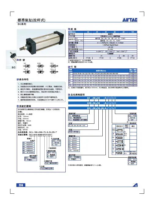
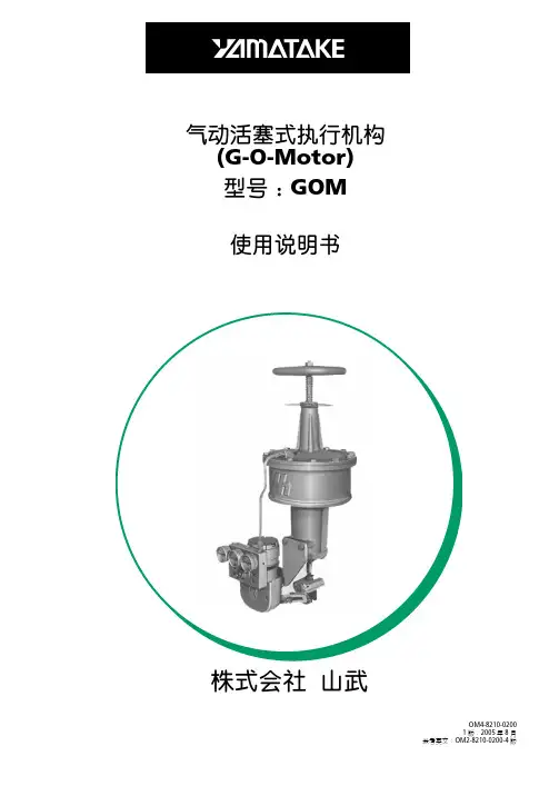
气缸说明书
- 格式:pdf
- 大小:1.12 MB
- 文档页数:2

P n e u m a t i c A c c e s s o r i e sGDGCL2018877.963.4966 • 374Wilkerson FRL'sR08 Miniature RegulatorsFeatures:• 0-125 PSI adjusting range • balanced valve design • self-relieving standard • n on-rising push/pull locking adjustment knob • t wo ⅛" NPT gauge ports standard on models without gauge, one ⅛" NPT gauge port standard on models with gauge - can be used for additional outlet ports.• m odels with gauge are supplied with a 0-160 flush mount style gauge • m odels supplied without gauge use a GC620 gauge.• p anel mount nuts sold separately • maximum operating conditions:300 PSIG (20.7 bar) and 32°F to 150°F (0°C to66°C)RB3 Miniature Water RegulatorsFeatures:• 2-125 PSI adjusting range • s uitable for water and compressed air service • b rass construction - wetted parts • n on-relieving spring-loaded diaphragm • p anel mount nut included • t wo ⅛" NPT gauge ports standard • m odels supplied without gauge use a GC620 gauge • maximum operating conditions:300 PSIG (20.7 bar) and 40°F to 125°F (4°C to 52°C)See pages 397 to 400 for accessories.BB3 Miniature Filters / Regulatorstransparent bowlFeatures:• 2-125 PSI adjusting range • 5 micron element • .5 oz. bowl •s elf-relieving• supplied with a GC620 gauge • maximum operating conditions:- t ransparent bowl: 125 PSIG (8.6 bar) and 40°F to 125°F (4.4°C to 52°C)- m etal bowl: 300 PSIG (20.7 bar) and 40°F to 125°F (4.4°C to52°C)SCFM ratings at 150 PSIG inlet pressure.FRL's are designed for air service only, unless otherwise indicated.SCFM ratings at 100 PSIG inlet pressure.SCFM ratings at 100 PSIG inlet pressure.。

Pressure Tube KitInstallation InstructionsPart No.311166-755NOTE:Read the entire instruction manual before starting theinstallation.This symbol→indicates a change since the last issue.SAFETY CONSIDERATIONSInstalling and servicing of heating equipment can be hazardousdue to gas and electrical components.Only trained personnelshould install or service heating equipment.Untrained personnel can perform basic maintenance functionssuch as cleaning coils or cleaning and replacing filters.All otheroperations should be performed by trained service personnel.When working on heating equipment,observe precautions in theliterature,on tags,and on labels attached to the unit.Follow all safety codes.Wear safety glasses and work gloves.Have a fire extinguisher available.Recognize safety information.This is the safety-alert symbol.When you see this symbol on the furnace and in instructions ormanuals,be alert to the potential for personal injury.Understand the signal words,DANGER,WARNING,and CAU-TION.These words are used with the safety-alert symbol.DAN-GER identifies the most serious hazards which will result in severepersonal injury or death.WARNING signifies a hazard which-could result in personal injury or death.CAUTION is used toidentify unsafe practices which may result in minor personalinjury or product and property damage.NOTE is used to highlightsuggestions which will result in enhanced installation,reliability,or operation.FIRE,EXPLOSION AND ELECTRICAL SHOCK HAZ-ARDFailure to follow this warning could result in personal injury,death and/or property damage.Turn off gas and electrical supplies to unit before beginningany installation or modification.Follow operating instruc-tions on label attached to furnace.UNIT DAMAGE HAZARDFailure to follow this caution may result in improper anddangerous operation.Label all wires prior to disconnection when servicing con-trols.INTRODUCTIONThis instruction manual covers installation of the pressure tube kitPart No.311166-755in all gas-fired condensing furnaces.DESCRIPTION AND USAGEThis pressure tube kit is designed for use when replacement of thefactory-installed tubing is required.This kit is for use with models320AAZ,321AAZ,340MAV,345MAV,350MAV,351DAS,352MAV,355MAV,340AAV,350AAV,352AAV,355AAV,398AAV,398AAZ,398BAZ,399AAZ,490AAV,58DX,58DXA,58DXC,58MCA,58MSA,58MVP,58MTA,58MXA,58MCB,58MVB,58MTB,58MXB,58SX,58SXA,58SXB,58SXC,58VCA,58VUA,PG9MAA,andPG9MAB Gas-Fired Condensing Furnaces.This pressure tube kit contains the following items:Tubing(1length to be cut to size)3Plastic tee3Clamps18Installation Instructions1INSTALLATION1.Turn off gas and electrical supplies to unit.2.Remove furnace door.3.Cut tubing to proper length as required.Refer to appropriatefigure for required tubing lengths as shown in Table1.4.Install clamps(provided in kit)on ends of new tubes.NOTE:Pressure tubing in units may be routed slightly differentthan what is shown in diagrams.Where possible,refer to tubinglabel on unit.5.Replace all tubing called out in proper figures.NOTE:Remove and replace1tube at a time.Ensure tubing isrouted in same manner as original pressure tubing.6.Place pressure tube assembly behind casing clips(if appli-cable).Make sure the tubes are not to be kinked or pinched,asthis will affect furnace operation.7.Check pressure tubes to ensure connections are completed andsecure.8.Turn on gas and electrical supplies to unit.9.Check furnace for proper operation through2complete cycles.10.Reinstall furnace door.Cancels:IIK340M-40-75IIK340M-40-878-05Manufacturer reserves the right to discontinue,or change at any time,specifications or designs without notice and without incurring obligations.Book14Tab6a8aPC101Printed in U.S.A.Pg18-05→→→Table1—Reference Figure UsageMODEL NUMBER SERIES REFERENCE FIGURE 320AAZ All4321AAZ All5340AAV A and later series7340MAVA6 B,C,D(prior to2496A02149and after1098A02241),andlater series7 D(between2496A02149and1098A02241)8345MAVA(through1098A02241)8 A(after1098A02241)and later series7350AAV A and later series7350MAVA6 B,C,D(prior to2496A02149and after1098A02241)andlater series7 D(2496A02149through1098A02241),and later series8351DAS All10 352AAV A and later series11 352MAV All11 355AAV A and later series9 355MAV All9 398AAV All1 398AAZ All1 398BAZ All3 399AAZ All2490AAVA6 B,C,D(prior to2496A02149and after1098A02241),andlater series7 D(2496A02149through1098A02241)858DX All2 58DXA All2 58DXC All258MCA1006 100,120,130(prior to2496A02149and after1098A02241),and later series7 130(2496A02149through1098A02241)858MCB100and later series758MSA100(through1098A02241)8 100(after1098A02241),and later series758MTA All11 58MTB100and later series11 58MVB100and later series9 58MVP All958MXA1006 110,120,130(prior to2496A02149and after1098A02241)and later series7 130(2496A02149through1098A02241)858MXB100and later series7 58SX All1 58SXA All1 58SXB All3 58SXC All1 58VCA All5 58VUA All4PG9MAAA(through1098A02241)8 A after(1098A02241)and later series7PG9MAB A and later series72→Fig.1—Pressure Tube Connection Diagram for Models 398AAV,398AAZ,58SX,58SXA,and 58SXC FurnacesMaximum Pressure Tube Length*UNIT SIZE TUBE LENGTH (IN.)A B C D 040&06011139908011137-1/2910011157-1/2912011167-1/29*Shorter lengths may be required to avoid kinking tubing.This will depend upon the gas valve and pressure switch used.Refer to existing tubing lengths,if possible.A92078ABFig.2—Pressure Tube Connection Diagram for Models 399AAZ,58DX,58DXA,and 58DXC FurnacesMaximum Pressure Tube Length*UNIT SIZETUBE LENGTH (IN.)A B C D All62666*Shorter lengths may be required to avoid kinking tubing.This will depend upon the gas valve and the pressure switch used.Refer to existing tubing lengths,if possible.A920793Fig.3—Pressure Tube Connection Diagram for Models 398BAZ and 58SXB FurnacesMaximum Pressure Tube Length*UNIT SIZETUBE LENGTH (IN.)A B C D E F All51293-1/21-3/84-1/2*Shorter lengths may be required to avoid kinking tubing.This will depend upon the gas valve and the pressure switch used.Refer to existing tubing lengths,if possible.A92080TUBE AFig.4—Pressure Tube Connection Diagram for Models 320AAZ and 58VUA FurnacesMaximum Pressure Tube Length*UNIT SIZETUBE LENGTH (IN.)A B C D E All512954*Shorter lengths may be required to avoid kinking tubing.This will depend upon the gas valve and the pressure switch used.Refer to existing tubing lengths,if possible.A92081A4Fig.5—Pressure Tube Connection Diagram for Models 321AAZ and 58VCA FurnacesMaximum Pressure Tube Length*UNIT SIZETUBE LENGTH (IN.)A B C D E All626644*Shorter lengths may be required to avoid kinking tubing.This will depend upon the gas valve and the pressure switch used.Refer to existing tubing lengths,if possible.A92082TUBE C5Fig.6—Pressure Tube Connection Diagram for Series A Models of 340MAV,350MAV,and 490AAV and Series 100Models of 58MCA and 58MXA 40–in.Tall Multipoise Furnaces (Upflow Orientation Shown)Maximum Pressure Tube Length*UNIT SIZETUBE LENGTH (IN.)A B C D E†04081328-3/418-1/206081328-3/418-1/208081328-3/420-1/210081328-3/420-1/212081328-3/420-1/2*Shorter lengths may be required to avoid kinking tubing.This will depend upon the gas valve and the pressure switch used.Refer to existing tubing lengths,if possible.†Length will vary depending on location of furnace condensate trap.A94267CONDENSATE TRAP6Fig.7—Pressure Tube Connection Diagram in 40in.Tall multipoise Furnace (Upflow Orientation Shown)for Models 340MAV,350MAV,and 490AAV Series B,C,D (prior to 2496A02149and after 1098A02241)and later series;Models 58MCA and 58MXA Series 110,120,130(prior to 2496A02149and after 1098A02241)and later series;Model 345MAV Series A (after 1098A02241)and later series;Model 58MSA Series 100(after 1098A02241)and later series;Model PG9MAA Series A (after 1098A02241)and later series;Model PG9MAB Series A and later series;Models 340AAV and 350AAV Series A and later series;Models 58MCB and 58MXB Series 100and later seriesMaximum Pressure Tube Length*UNIT SIZETUBE LENGTH (IN.)A B C D E†0405101-1/29-1/4240605101-1/29-1/424080611-1/21-1/29-1/424100611-1/21-1/29-1/424120811-1/21-1/29-1/424*Shorter lengths may be required to avoid kinking tubing.This will depend upon the gas valve and pressure switch used.Refer to existing tubing lengths,if possible.†Length will vary depending on location of furnace condensate trap.A94268BURNER ENCLOSUREGAS VALVEPRESSURE SWITCH 7Fig.8—Pressure Tube Connection Diagram (Upflow Orientation Shown)for Models 340MAV,345MAV,350MAV,58MCA,58MSA,58MXA,PG9MAA and 490AAV(between 2496A02149and 1098A02241)UNIT SIZETUBE LENGTH (IN.)A B C D E†0405101-1/215-1/4220605101-1/215-1/422080611-1/21-1/215-1/422100611-1/21-1/215-1/422120811-1/21-1/215-1/422140811-1/21-1/215-1/422*Shorter lengths may be required to avoid kinking tubing.This will depend upon the gas valve and pressure switch used.Refer to existing tubing lengths,if possible.†Length will vary depending on location of furnace condensate trap.A962528Fig.9—Pressure Tube Connection Diagram in a 40–in.Tall Multipoise Furnace (Upflow Orientation Shown)forModels 355MAV,355AAV,58MVP,and 58MVBMaximum Pressure Tube Length*UNIT SIZETUBE LENGTH (IN.)A B C D E†0406-1/213-1/2310-1/2240606-1/213-1/2310-1/2240806-1/213-1/2310-1/2241006-1/213-1/2310-1/224120813-1/21-1/210-1/224*Shorter lengths may be required to avoid kinking tubing.This will depend upon the gas valve and pressure switch used.Refer to existing tubing lengths,if possible.†Length will vary depending on location of furnace condensate trap.A942699Fig.10—Pressure Tube Connection Diagram for Model 351DAS 40–in.Tall Downflow FurnacesMaximum Pressure Tube Length*UNIT SIZETUBE LENGTH (IN.)A B C D†E 080611-1/21-1/22624*Shorter lengths may be required to avoid kinking tubing.This will depend upon the gas valve and pressure switch used.Refer to existing tubing lengths,if possible.†Length will vary depending on location of furnace condensate trap.A99058GAS VALVE 10Fig.11—Pressure Tube Connection Diagram in a 40in.Tall Multipoise Furnace (Upflow Orientation Shown)forModels 352MAV,352AAV,58MTA,and 58MTBMaximum Pressure Tube Length*UNIT SIZETUBE LENGTH (IN.)A B C D E†0605101-1/2624080611-1/21-1/2624100611-1/21-1/2624120811-1/21-1/2624*Shorter lengths may be required to avoid kinking tubing.this will depend upon the gas valve and pressure switch used.Refer to existing tubing lengths,if possible.†Length will vary depending on location of furnace condensate trap.A01079BURNER ENCLOSURE11Copyright2005Carrier Corporation340m4087Manufacturer reserves the right to discontinue,or change at any time,specifications or designs without notice and without incurring obligations. Book14PC101Printed in U.S.A.Pg128-05Tab6a8a。

气缸的使用方法
气缸是一种常用的气动执行元件,广泛应用于工业自动化生产线、机器人、航空航天等领域。
在使用气缸时,需要注意以下几点:
1. 选择合适的气缸型号:根据需要执行的任务和工作环境条件,选
择适合的气缸型号,包括气缸的尺寸、工作压力、工作介质等。
2. 连接气源:将气缸与气源连接,通常使用气管或接头等连接件。
3. 安装气缸:根据具体任务的要求,将气缸安装在合适的位置上,
通常使用支架或固定座等固定件。
4. 调节气缸:根据具体任务的要求,调节气缸的行程、速度、力量
等参数,通常使用控制阀或压力调节器等控制元件。
5. 使用气缸:根据具体的控制方式,使用气缸完成相应的任务,例
如推动物体、抓取物体、旋转等。
除了以上基本使用方法外,还应注意气缸的维护保养,包括定期清洗和加油润滑等。
同时,为了确保安全使用,应严格遵循气缸的使用说明书和相关安全规范。