机械设计类英文文献及翻译
- 格式:doc
- 大小:72.00 KB
- 文档页数:18

附录附录A: 英文文献与中文参考译文At89S51 monolithic integrated circuit is the low power loss which ATMEL Corporation promotes, the high performance CMOS8 position monolithic integrated circuit, internal including the 4K bytes programmable Flash read-only program memory, the component uses the ATMEL Corporation's high density, the non-volatility storage technology production, compatible standard 8051 command systems and pin, and already may use the online programming (ISP), also the available conventional routes carry on the programming and the general 8 microprocessors in the monolithic integrated circuit chip, the ATMEL Corporation's function is formidable, the low end AT89S51 monolithic integrated circuit provides many high performance-to-price ratios the application situations, but applies nimbly in each kind of control domain, the debugging is convenient.The sensor marched the automobile, medical, the industry and astronautics application domain on a large scale. Perhaps you not yet saw any changes . In safe, convenient, aspect day by day aggregate demands and so on entertainment as well as efficiency factor, in addition from all over the world politics the government office's law will enablesensor's application to obtain the unprecedented inflation.Besides estimated that sensor in wireless and consumable domain application sudden inflation, you will also understand why passed on the feeling producer to finish the rapid development huge market and the application domain hopefully before 2010. In these sensors the majority will be microcomputer electrical system series (MEMS) and the micro system technology (MST) type, as well as application prospect very broad micro sensor. regarding the automobile system, the sensor producer may discover the massive sensing application very easily, not only includes the survey to pass on the feeling pressure, moreover including through sensing system survey inertia, position, proximity, temperature, speed of flow, strength strong , tensity, torque, vibration and inclined condition. Uses in surveying these parameters the sensing technology to be various. Passes to believe with automobile technology center technical personnel Alex Cade that “the automobile domain's sensing demand is assuming the caper type to increase to be long.”He enumerated the chassis control, the vehicles localization/position, the object survey, the vision to strengthen, the automobile environment to heat up , well ventilated, sensor's and so on air conditioning as well as engine and transmission control growth domains. The enhancement vehicles stability is only in numerous example one which his enumerates. US National highway Transportation Administrative bureau (NHTSA) vehicle increased recentlyabout the side collision security aerocyst's proposition request in each steam on the two to six sensors. Although this proposition has not been forced the request use, but American, European and date the this automobile producer indicated that stemming from the security concern, they will finish before 2010 leans for all vehicles installment the surface collision security aerocyst. Certain automobile supplier, like TRW and Delphi ( the latter reaction rate the former quick) apply group of accelerometers and the pressure transmitter in the side collision security aerocyst. the automobile inertia sensing has become other hot spot. In fact, Motorola and Analog Devices () proposed that the use inertia sensor element group will manage massive will use in the vehicles tendency, guidance , the security and the electron steering application sensing function (illustration 1). “the anti-lock braking system, the electronic braking force distribution system, follow the mark control system and of the initiative yaw control system interaction enable the automobile to have the dynamic stability,” Analog Devices said high-level using Engineer Harvey Weinberg. Motorola John P. Schuster adds: “the part group method may use core platform support many kinds of applications. It take astronautics gyroscope as the foundation, and the cost is low, the volume is small, may apply in the automobile.” light sensing technology budding the one kind used in the survey engine pressure by the Optrand development the new method using one kind ofmulti-purpose equipment, this equipment loaded one based on the optical fiber technology's pressure transmitter to use in diesel engine's preheating plug. Forced induction the preheating plug by one induction, a fiber optics and many signal control electronic component is composed, when the pressure surpasses 5 Pakistan , it refers to the frequency changer to be able water-cooled to provide 62% precisions, when the pressure is lower than 5 Pakistan, the error is lower than 0.2 Pakistan. this company estimated that will use this equipment for the first time in 2007. the Honeywell plan uses the light sensing technology in low cost's non-key input's passive system, the part uses this technique the technique the product to be possible to insert automobile's door knob. This sensor will contain one to be loaded with transceiver key shape optics Yuan . In order to enter in the vehicle, the vehicle owner has laid aside a key shape part between the vehicle door knob and the automobile body. the Hall effect sensor will find in the numerous automobile functions applies the place, including induction deceleration and brake pedal's position, cam shaft position and rotational speed, barometric pressure as well as branch pipe absolute pressure (MAP). Infineon Technologies AG application Engineer Werner Roessler believed that active Hall effect sensor available in power transmission control as well as cam and crank and so on related application. “compares with the passive sensor, this has provided the higher accuracy, the better startstrategy, and has surveys the crank to start a position ability,” he said. Melexis the Inc. plan uses in this technology inducing the non-contact position. new induction model the electric field induction use electrode and between them the electric field works. Freescale Semiconductor believed that its may use for to substitute the security aerocyst and other use sensor. “this induction method is helpful in makes the security aerocyst to intellectualize, because had not only considered passenger's forehead position (i.e. forehead whether to move?), moreover had considered passenger's volume and the weight, the aerocyst premature will not open,” Freescale application Engineer Don Laybourn said. this kind of sensor may install, in the border or other places have on electrode's steering wheel, like this may determine that the steering wheel is is loosened otherwise (for example, when a pilot falls asleep or cripples when), will then send out the warning signal. This method type may also let the vehicles with the stop slowly down. the vehicles seat electrode may when the vehicles go determined that in the pilot position nobody's situation carries on the brake to the vehicles. this will prevent the vehicles to enter the out of control condition, for example, when the automobile anchors when the pitch. The glass rain water and accumulates the frost to induce is other one kind of application.参考译文:单片机是ATMEL公司推出的低功耗,高性能CMOS8位单片机,片内含4K bytes 的可编程的Flash只读程序存储器,器件采用ATMEL 公司的高密度、非易失性存储技术产生,兼容标准8051指令系统及引脚,并且既可采用在线编程(ISP),也可用传统方法进行编程及通用8位微处理器于单片机芯片中,ATMEL公司的功能强大,低价位的AT89S51单片机提供许多高性价比的应用场合,可灵活应用于各种控制领域,调试非常方便,使用也非常灵活。

Engine Operating PrinciplesMost automobile engines are internal combustion,reciprocating 4-stroke gasoline engines,but other types have been used,including the diesel,the rotary(wankel),the 2-srtoke,and stratified charge.Reciprocating means up and dowm or banck and forth ,It is the up and down action of a piston in the cylinder blick,or engine block.The bilck is an iron or aluminum casting that contains engine cylinders and passges called water jackets for coolant circulation.The top of the block is convered with the cylinder head.Which forms the combustion chanber.The bottom of the block is covered with an oil pan or oil sump.Power ia produced by the linear motion of a piston in a cylinder.However,this linear motion must be changed into rotary motion to turn the wheels of cars of trucks.The piston is attached to the top of a connecting rod by a pin ,called a piston pin or wrist pin.The bottom of the connecting rod is attached to the crankshaft.The connecting rod transmits the up-and-down motion of the piston to the crankshaft,which changes it into rotary motion.Term: stroke is used to indicate the movement within thecylinder piston, piston stroke is the distance from the engine type according to need two-stroke or four-stroke cycle to finish a job and four stroke engines are also called otto engine, in order to commemorate German engineers otto, he is the first application in 1876, the principle of in four stroke engines, cylinder piston required to complete a four-stroke cycle, each stroke work according to their behavior named respectively: intake stroke, compression stroke, function and exhaust stroke.1. Intake strokeWhen the piston moves down, spray the mixture through open after entering the inlet valve, in order to achieve maximum cylinder amount of inlet in Detroit, arrive before BDC 10 °, open and exhaust has 20 ° to open the inlet valve overlap, has been opened to the pistons to come fully into the mixture after about 50 °.2. Compression strokeThe piston start moving up huge inlet valve closed, and the mixture in the combustion chamber, according to the different factors including compression compression ratio, the throttle valve, pressure revs up to about 1 mpa, close to the top, the spark plug stroke produces the spark gap in the breakdown ignition mixture lighting.3. Doing workBurning gas pressure of inflation rose to 3.5 mpa, promote the piston moves to the cylinder, and exhaust door open.4 gas strokeWith exhaust before more open about 50 °, piston, make up in the air pressure drops in exhaust stroke, reduce backpressure, discharge waste piston stroke, for the next intake, normally, inlet in exhaust before opening.Only the engine keep running, each cylinder within four four-stroke cycle continuously.Two stroke engine also through the four-stroke cycle to complete a job but intake stroke, compression stroke for a stroke, do work schedule another stroke, the four-stroke cycle and two terms two travel itinerary is called the term two-cycle but actually not so accurate. However,the intake and the compression actions are combined in one seroke,and the power and exhaust actions are combined in the other stroke.The term 2-stroke cyde or 2-stroke is preferred to the term 2-cyde,which is really not accurate.In automobile engines,all pistons are attached to a single crankshaft.the more cylinders an engine has,the more power strokes produced for cach revolution.This means that an 8-cylinder engine runs more smoothly bacause the poweratrokes are closer togther in time and in degrees of engine rotation.The cylinders of multi-cylinder automotive engines arranged in one of three ways.1.Inline engines use a single block of cylinder.Most 4-cylinder and any 6-cylinder engines are of this design.The cylinders do not have to be vertical.They can be inclined either side.2.V-type engines use two equal bands of cylinders,usually inclined 60 degrees or 90 degrees from the cach other.Most V-type engines have 6 or 8 cylinders,although v-4 and v-12 engines have been built.3.Horizontally opposed,or pancake engines have two equal banks of cylinders 180 degrees apart.These space saving engine designs are often air-cooled,and are found in the Chevrolet Carvair,Porsches,Subaus,and Volkswagens.Subaus design is liquid cooled.are often air-cooled,and are found in the Chevrolet Carvair,Porsches,Subaus,and Volkswagens.Subaus design is liquid te-model Volkswagen vans use a liquid-cooled version of the air cooled VWhorizontally opposed engine.发动机工作原理大多数汽车的发动机是内燃机,往复四冲程汽油机,但是也有使用其它类型的发动机,包括柴油机,转子发动机,二冲程发动机和分成燃烧发动机。

Unit 1 MetalsUnit 2 Selection of Construction Materials工程材料的选择淬透性:指在规定条件下,决定钢材淬硬深度和硬度分布的特性.即钢淬火时得到淬硬层深度大小的能力,它表示钢接受淬火的能力.钢材淬透性好与差,常用淬硬层深度来表示.淬硬层深度越大,则钢的淬透性越好.钢的淬透性是钢材本身所固有的属性,它只取决于其本身的内部因素,而与外部因素无关。
钢的淬透性主要取决于它的化学成分,特别是含增大淬透性的合金元素及晶粒度,加热温度和保温时间等因素有关。
淬透性好的钢材,可使钢件整个截面获得均匀一致的力学性能以及可选用钢件淬火应力小的淬火剂,以减少变形和开裂。
淬透性主要取决于其临界冷却速度的大小,而临界冷却速度则主要取决于过冷奥氏体的稳定性,影响奥氏体的稳定性主要是:1.化学成分的影响碳的影响是主要的,当C%小于1。
2%时,随着奥氏体中碳浓度的提高,显著降低临界冷却速度,C曲线右移,钢的淬透性增大;当C%大于时,钢的冷却速度反而升高,C曲线左移,淬透性下降。
其次是合金元素的影响,除钴外,绝大多数合金元素溶入奥氏体后,均使C曲线右移,降低临界冷却速度,从而提高钢的淬透性。
2.奥氏体晶粒大小的影响奥氏体的实际晶粒度对钢的淬透性有较大的影响,粗大的奥氏体晶粒能使C曲线右移,降低了钢的临界冷却速度。
但晶粒粗大将增大钢的变形、开裂倾向和降低韧性。
3。
奥氏体均匀程度的影响在相同冷度条件下,奥氏体成分越均匀,珠光体的形核率就越低,转变的孕育期增长,C曲线右移,临界冷却速度减慢,钢的淬透性越高.4.钢的原始组织的影响钢的原始组织的粗细和分布对奥氏体的成分将有重大影响.5。
部分元素,例如Mn,Si等元素对提高淬透性能起到一定作用,但同时也会对钢材带来其他不利的影响。
可锻性(forgeability)金属具有热塑性,在加热状态(各种金属要求温度不同),可以进行压力加工,称为具有可锻性。
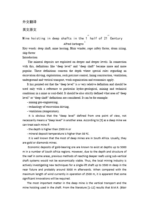
外文翻译英文原文Mine hoisting in deep shafts in the 1sthalf of 21stCenturyAlfred Carbogno1Key words: deep shaft, mine hosting, Blair winder, rope safety factor, drum sizing, skip factorIntroductionThe mineral deposits are exploited on deeper and deeper levels. In connection with this, definitions like “deep level” and “deep shaft” became more and more popular. These definitions concern the depth where special rules regarding an excavation driving, exploitation, rock pressure control, lining construction, ventilation, underground and vertical transport, work organization and economics apply.It has pointed out that the “deep level” is a very relative definition and should be used only with a reference to particular hydro-geological, mining and technical conditions in a mine or coal-field. It should be also strictly defined what area of “deep level” or “deep shaft” definitions are considered. It can be for example: - mining geo-engineering,- technology of excavation driving,- ventilation (temperature).It is obvious that the “deep level” defined from one point of view, not necessarily means a “deep level” in another area. According to [5] as a deep mine we can treat each mine if:- the depth is higher than 2300 m or- mineral deposit temperature is higher than 38 ºC.It is well known that the most of deep mines are in South Africa. Usually, they are gold or diamonds mines.Economic deposits of gold-bearing ore are known to exist at depths up to 5000 m in a number of South Africa regions. However, due to the depth and structure of the reef in some areas, previous methods of reaching deeper reefs using sub-vertical shaft systems would not be economically viable. Thus, the local mining industry is actively investigating new techniques for a single-lift shaft up to 3500 m deep in the near future and probably around 5000 m afterwards. When compared with the maximum length of wind currently in operation of 2500 m, it is apparent that some significant innovations will be required.The most important matter in the deep mine is the vertical transport and the mine hoisting used in the shaft. From the literature [1-12] results that B.M.R. (BlairMulti-Rope) hoist is preferred to be used in deep mines in South Africa. From the economic point of view, the most important factors are:- construction and parameters of winding ropes (safety factor, mainly),- mine hoisting drums capacity,This article of informative character presents shortly above-mentioned problems based on the literature data [1-12]. Especially, the paper written by M.E. Greenway is very interesting [3]. From two transport systems used in the deep shaft, sub-vertical and the single-lift shaft systems, the second one is currently preferred. (Fig.1.) [6]Hoisting InstallationThe friction hoist (up to 2100 m), single drum and the double drum (classic and Blair type double drum) hoist are used in deep shafts in South Africa.Drum windersDrum winders are most widely used in South Africa and probably in the world. Three types of winders fall into this category- Single drum winders,- Double drum winders,- Blair multi-rope winders (BMR).Double drum windersTwo drums are used on a single shaft, with the ropes coiled in opposite directions with the conveyances balancing each other. One or both drums are clutched to the shaft enabling the relative shaft position of the conveyances to be changed and permitting the balanced hoisting from multiple levelsThe Blair Multi-Rope System (BMR)In 1957 Robert Blair introduced a system whereby the advantage of the drum winder could be extended to two or more ropes. The two-rope system developedincorporated a two-compartment drum with a rope per compartment and two ropes attached to a single conveyance. He also developed a rope tension-compensating pulley to be attached to the conveyance. The Department of Mines allowed the statutory factor of safety for hoisting minerals to be 4,275 instead of 4,5 provided the capacity factor in either rope did not fall below the statutory factor of 9. This necessitated the use of some form of compensation to ensure an equitable distribution of load between the two ropes. Because the pulley compensation is limited, Blair also developed a device to detect the miscalling on the drum, as this could cause the ropes to move at different speeds and so affect their load sharing capability. Fig.2 shows the depth payload characteristics of double drum, BMR and Koepe winders.The B.M.R. hoist is used almost exclusively in South Africa, probably because they were invented there, particularly for the deep shaft use. There is one installation in England. Because of this hoist's physical characteristics, and South African mining rules favouring it in one respect, they are used mostly for the deep shaft mineral hoisting. The drum diameters are smaller than that of an equivalent conventional hoist, so one advantage is that they are more easily taken underground for sub-shaft installations.A Blair hoist is essentially a conventional hoist with wider drums, each drum having a centre flange that enables it to coil two ropes attached to a skip via two headsheaves. The skip connection has a balance wheel, similar to a large multi-groove V-belt sheave, to allow moderate rope length changes during winding. The sheaves can raise or lower to equalize rope tensions.The Blair hoist's physical advantage is that the drum diameter can be smaller than usual and, with two ropes to handle the load, each rope can be much smaller. The government mining regulations permit a 5 % lower safety factor at the sheave for mineral hoisting with Blair hoists. This came about from a demonstration by the% permits the Blair hoists to go a little deeper than the other do.On the other hand, the mining regulations require a detaching hook above the cage for man hoisting. The balance wheel does not suit detaching hooks, so a rope-cutting device was invented to cut the ropes off for a severe overwind. This was tested successfully but the Blair is not used for man winding on a regular basis.The B.M.R. hoist has been built in three general styles similar to conventional hoists. The three styles are (Fig. 3 and 4):The gearless B.M.R. hoist at East Dreifontein looks similar to an in-line hoist except that the drums are joined mechanically and they are a little out of line with each other. This is because each drum directly faces its own sheaves for the best fleet angle. The two hoist motors are fed via thyristor rectifier/inverter units from a common 6.6-KV busbar. The motors are thus coupled electrically so that the skips in the shaft run in balance, similar to a conventional double-drum hoist. Each motor alternates its action as a DC generator or DC motor, either feeding in or taking out energy from the system. The gearless Blair can be recognized by the offset drums and the four brake units. A second brake is always a requirement, each drum must have two brakes, because the two drums have no mechanical connection to each other. Most recent large B.M.R. hoists are 4.27 or 4.57 m in diameter, with 44.5 ÷ 47.6 mm ropes [1].In arriving at a drum size the following parameters have been used:- The rope to be coiled in four layers,- The rope tread pressure at the maximum static tension to be less than 3,2 MPa, - The drum to rope diameter ratio (D/d) to be greater than 127 to allow for a rope speed of 20 m/s.With the above and a need to limit the axial length of the drums, a rope compartment of 8,5 m diameter by 2,8 m wide, was chosen. The use of 5 layers of coiled rope could reduce the rope compartment width to 2,15 m but this option hasbeen discarded at this stage because of possible detrimental effects on the rope life.One problem often associated with twin rope drum hoists is the rope fleeting angle. The axial length of the twin rope compartment drums requires wide centres for the headgear sheaves and conveyances in the shaft. To limit the diameter of the shaft, the arrangement illustrated in Fig. 4 has been developed and used on a hoist still to be installed. Here, an universal coupling or Hooke’s Joint has been placed between the two drums to allow the drums to be inclined towards the shaft center and so alleviate rope fleeting angle problem, even with sheave wheels at closer centres [11].The rope safety factorThe graphs in Fig. 5 illustrate the endload advantage with reducing static rope safety factors. While serving their purpose very well over the years, the static safety factor itself must now be questioned. Static safety factors, while specifically relating to the static load in the rope were in fact established to take account of:a. Dynamic rope loads applied during the normal winding cycle, particularly during loading, pull-away, acceleration, retardation and stopping,b. Dynamic rope loads during emergency braking,c. Rope deterioration in service particularly where this is of an unexpected or unforeseen nature.If peak loads on the rope can be reduced so that the peak remains equal to or less than that experienced by the rope when using current hoisting practices with normal static rope safety factor, the use of a reduced static rope safety factor can be justified. The true rope safety factor is not reduced at all. This is particularly of importance during emergency braking which normally imposes the highest dynamic load on the rope. Generally, the dynamic loads imposed during the skip loading, cyclic speed changes and tipping will be lower than for emergency braking but their reduction will of course improve the rope life at the reduced static rope safety factor. The means, justification and safeguards associated with a reduced static safety factor are discussed in [4,7,9,12].Based on the static rope safety factor of 4, the rope endload of 12843 kg per rope can be achieved. With twin ropes, this amounts to an endload of 25686 kg. With a conveyance based on 40 % of payload of 18347 kg with a conveyance of 7339 kg. There are hoisting ropes of steel wires strength up to Rm = 2300 MPa (Rm up to 2600 MPa [6] is foreseen) used in deep shafts. There are also uniform strength hoisting ropes projected [2,8].ConveyancesThe winding machines made from a light alloy are used in hoisting installations in deep shafts. The skip factor (S) has been defined as the ratio of empty mass of the skip (including ancillary equipment such as rope attachments, guide rollers, etc) tothe payload mass. If the rope end load is kept constant, a lower skip factor implies a larger payload – in other words, a more efficient skip from a functional point of view. However, the higher the payload for the same rope end load, the larger the out-of-balance load –implying a more winder power going hand in hand with the higher hoisting capacity. If, on the other hand, the payload is fixed, a lower skip factor implies a lower end load and a smaller rope-breaking load requirement. Under these conditions, an out-of-balance load attributable to the payload would remain the same, but that due to the rope would reduce slightly. The sensitivity of depth of wind and hoisting capacity to skip the factor is illustrated in Fig. 6 and 7. A reduction of skip factor from 0,5 to 0,4 results in a depth gain of about 40 m for Blair winders and 50 m for single-rope winders. The increase of hoisting capacity for a reduction of skip factor by about 0,1 is about 10 %.Typical values for the “skip factor” are about 0,6 for skips and about 0,75 for cages for men and material hoisting. Reducing skip factors to say about 0,5 is a tough design brief and the trade-offs between lightweight skips and maintainability and reliability soon become evident in service.The weight can be readily reduced by omitting (or reducing in thickness) skip liner plates but this could reduce skip life by wear of structural plate leading to the high maintenance cost or more frequent maintenance to replace thinner liner plates. Similarly, if the structural mass is saved by reducing section sizes or changing the material from steel to aluminium for example, the structural reliability is generally reduced and the fatigue cracking becomes more efficient.Some success has been achieved in operating large capacity all –aluminium skips with low skip factors but the capital cost is high and a very real hoisting capacity constrain must exist before the additional cost is warranted. It would appear that the depth and hoisting capacity improvements are better made by reducing the rope factor of safety and increasing the winding speed. The philosophy of the skip design should be to provide robust skips with reasonable skip factors in the range of 0,5 to 0,6 that can be hoisted safely and reliably at high speeds and that are tolerant to the shaft guide misalignment.It should be noted that some unconventional skips have been proposed (but not yet built and tested) that could offer skip factors as low as 0,35.ConclusionsThe first installation of Blaire hoists took place in 1958. From that time we can observe a continuous development of this double-rope, double-drum hoists. Currently, they are used up to the depth of 3 150 m (man/material hoist at the Moab Khotsong Mine, to hoist 13 500 kg in a single lift, at 19,2 m/sec, using 2 x 7400 kW AC cyclo-convertor fed induction motors). The Blair Multi-Rope system can be use either during shaft sinking or during exploitation. The depth range for them is 715 to 3150 m and the maximum skip load is 20 tons.In South Africa in deep shafts single lift systems are preferred.References[1] BAKER. T.J.: New South African Drum Hoisting Plants. CIM Bulletin, No 752, December 1994, p. 86-96.[2] CARBOGNO, A.: Winding Ropes of Uniform Strength. 1st International Conference LOADO 2001. Logistics and Transport. Hotel Permon, High Tatras, June 6th –8th 2001 p.214-217.[3] GREENWAY, M.E.: An Engineering Evaluation of the Limits to Hoisting from Great Depth. Int. Deep Mining Conference: Technical Challenges in Deep Level Mining, Johannesburg, SAIMM, 1990 p.449-481.[4] HECKER, G.F.K.: The Safety of Hoisting Ropes in Deep Mine Shafts. International Deep Mining Conference: Technical Challenges in Deep Level Mining. Johannesburg, SAIMM, 1990 p. 831-838.[5] HILL, F.G, MUDD J,B: Deep Level Mining in South African Gold Mines. 5th International mining Congress 1967, Moscow, p. 1 –20.[6] LANE, N.M: Constraints on Deep-level Sinking – an Engineering Point of View. The Certificated Engineer, vol. 62, No6, December 1989/January 1991 p. 3-9.[7] LAUBSCHER, P.S.: Rope Safety Factors for Drum Winders –Implications of the Proposed Amendments to the Regulations. Gencor Group, 1995 Shaft Safety Workshop. Midrand, Johannesburg, November 1995, paper No 5 p.1-11.[8] MAC DONALD, D.H., PIENAAR, F.C.: State of the Art and Future Developments of Steel Wire Rope in Sinking and Permanent Winding Operations. Gencor Group, Shaft Safety Workshop Magaliesberg, 1994, paper No 13, p. 1-21.[9] MCKENZIE, I.D.: Steel Wire Hoisting Ropes for Deep Shafts. International Deep Mining Conference: Technical Challenges in Deep Level Mining. Johannesburg, SAIMM, 1990 p. 839-844.[10] SPARG, E.N.: Development of SA- Designed and Manufactured Mine Winders. The South African Mechanical Engineer vol.35, No 10, October 1985 p. 418-423. [11] SPARG E,N.: Developments in Hoist Design Technology Applied to a 4000 m Deep Shaft. Mining Technology, No 886, June 1995, p. 179-184.[12] SYKES, D.G., WIDLAKE, A.C.: Reducing Rope Factors of Safety for Winding in Deep Levels Shafts. International Deep Mining Conference. Technical Challenges in Deep Level Mining. Johannesburg, SAIMM, 1990 p. 819-829.中文译文21 世纪前半叶矿井挖掘机在深井中的应用关键词: 深井,矿井挖掘机,布莱尔挖掘机, 钢丝绳安全要素,滚筒尺寸,骤变要素介绍矿物沉淀物在越来越深的水平上被开采。

附录附录ADrive axle/differentialAll vehicles have some type of drive axle/differential assembly incorporated into the driveline. Whether it is front, rear or four wheel drive, differentials are necessary for the smooth application of engine power to the road.PowerflowThe drive axle must transmit power through a 90° angle. The flow of power in conventional front engine/rear wheel drive vehicles moves from the engine to the drive axle in approximately a straight line. However, at the drive axle, the power must be turned at right angles (from the line of the driveshaft) and directed to the drive wheels.This is accomplished by a pinion drive gear, which turns a circular ring gear. The ring gear is attached to a differential housing, containing a set of smaller gears that are splined to the inner end of each axle shaft. As the housing is rotated, the internal differential gears turn the axle shafts, which are also attached to the drive wheels.Fig 1 Drive axleRear-wheel driveRear-wheel-drive vehicles are mostly trucks, very large sedans and many sports car and coupe models. The typical rear wheel drive vehicle uses a front mounted engine and transmission assemblies with a driveshaft coupling the transmission to the rear drive axle. Drive in through the layout of the bridge, the bridge drive shaft arranged vertically in the same vertical plane, and not the drive axle shaft, respectively, in their own sub-actuator with a direct connection, but the actuator is located at the front or the back of the adjacent shaftof the two bridges is arranged in series. Vehicle before and after the two ends of the driving force of the drive axle, is the sub-actuator and the transmission through the middle of the bridge. The advantage is not onlya reduction of the number of drive shaft, and raise the driving axle of the common parts of each other, and to simplify the structure, reduces the volume and quality.Fig 2 Rear-wheel-drive axleSome vehicles do not follow this typical example. Such as the older Porsche or Volkswagen vehicles which were rear engine, rear drive. These vehicles use a rear mounted transaxle with halfshafts connected to the drive wheels. Also, some vehicles were produced with a front engine, rear transaxle setup with a driveshaft connecting the engine to the transaxle, and halfshafts linking the transaxle to the drive wheels.Differential operationIn order to remove the wheel around in the kinematics due to the lack of co-ordination about the wheel diameter arising from a different or the same rolling radius of wheel travel required, inter-wheel motor vehicles are equipped with about differential, the latter to ensure that the car driver Bridge on both sides of the wheel when in range with a trip to the characteristics of rotating at different speeds to meet the requirements of the vehicle kinematics.Fig 3 Principle of differentialThe accompanying illustration has been provided to help understand how this occurs.1.The drive pinion, which is turned by the driveshaft, turns the ring gear.2.The ring gear, which is attached to the differential case, turns the case.3.The pinion shaft, located in a bore in the differential case, is at right angles to the axle shafts and turns with the case.4.The differential pinion (drive) gears are mounted on the pinion shaft and rotate with the shaft .5.Differential side gears (driven gears) are meshed with the pinion gears and turn with the differential housing and ring gear as a unit.6.The side gears are splined to the inner ends of the axle shafts and rotate the shafts as the housing turns.7.When both wheels have equal traction, the pinion gears do not rotate on the pinion shaft, since the input force of the pinion gears is divided equally between the two side gears.8.When it is necessary to turn a corner, the differential gearing becomes effective and allows the axle shafts to rotate at different speeds .Open-wheel differential on each general use the same amount of torque. To determine the size of the wheel torque to bear two factors:equipment and friction. In dry conditions, when a lot of friction, the wheel bearing torque by engine size and gear restrictions are hours in the friction (such as driving on ice), is restricted to a maximum torque, so that vehicles will not spin round. So even if the car can produce more torque, but also need to have sufficient traction to transfer torque to the ground. If you increase the throttle after the wheels slip, it will only make the wheels spin faster.Fig 4 Conventional differential Limited-slip and locking differential operationFig 5 Limited-slip differentialDifferential settlement of a car in the uneven road surface and steeringwheel-driven speed at about the different requirements; but is followed by the existence of differential in the side car wheel skid can not be effective when the power transmission, that is, the wheel slip can not produce the driving force, rather than spin the wheel and does not have enough torque. Good non-slip differential settlement of the car wheels skid on the side of the power transmission when the issue, that is, locking differential, so that no longer serve a useful differential right and left sides of the wheel can be the same torque.Limited-slip and locking differential operation can be divided into two major categories:(1) mandatory locking type in ordinary differential locking enforcement agencies to increase, when the side of the wheel skid occurs, the driver can be electric, pneumatic or mechanical means to manipulate the locking body meshing sets of DIP Shell will be with the axle differential lock into one, thus the temporary loss of differential role. Relatively simple structure in this way, but it must be operated by the driver, and good roads to stop locking and restore the role of differential.(2) self-locking differential installed in the oil viscosity or friction clutch coupling, when the side of the wheel skid occurs when both sides of the axle speed difference there, coupling or clutch friction resistance on the automatic, to make certain the other side of the wheel drive torque and the car continued to travel. When there is no speed difference on both sides of the wheel, the frictional resistance disappeared, the role of automatic restoration of differentials. More complicated structure in this way, but do not require drivers to operate. Has been increasingly applied in the car. About non-slip differential, notonly used for the differential between the wheels, but also for all-wheel drive vehicle inter-axle differential/.Gear ratioThe drive axle of a vehicle is said to have a certain axle ratio. This number (usually a whole number and a decimal fraction) is actually a comparison of the number of gear teeth on the ring gear and the pinion gear. For example, a 4.11 rear means that theoretically, there are 4.11 teeth on the ring gear for each tooth on the pinion gear or, put another way, the driveshaft must turn 4.11 times to turn the wheels once. The role of the final drive is to reduce the speed from the drive shaft, thereby increasing the torque. Lord of the reduction ratio reducer, a driving force for car performance and fuel economy have a greater impact. In general, the more reduction ratio the greater the acceleration and climbing ability, and relatively poor fuel economy. However, if it is too large, it can not play the full power of the engine to achieve the proper speed. The main reduction ratio is more Smaller ,the speed is higher, fuel economy is better, but the acceleration and climbing ability will be poor.附录B驱动桥和差速器所有的汽车都装有不同类型的驱动桥和差速器来驱动汽车行驶。

江苏大学机械毕业设计电磁阀外文翻译附录Ⅰ:Magnetoelastic Torque Sensor Utilizing a Thermal Sprayed Sense-Element for Automotive Transmission ApplicationsBrian D. KilmartinSiemens VDO Automotive Corporation ABSTRACTA Magnetoelastic based Non-Contacting, Non-Compliant Torque Sensor is being developed by Siemens VDO for automotive transmission applications. Such a sensor would benefit the automotive industry by providing the feedback needed for precise computer control of transmission gear shifting under a wide range of road conditions and would also facilitate cross-platform usage of a common transmission unit.Siemens VDO has prototyped transmission torque sensors operating on the principle of Inverse- magnetostriction, also referred to as the Inverse-Joule Effect and the Villari Effect. Magnetostriction, first documented in the mid 1800’s, is a structural property of matter that defines a m aterial’s dimensional changes as a result of exposure to a magnetic field. Magnetostriction is caused when the atoms that constitute a material reorient in order to align their magnetic moments with an external magnetic field. This effect is quantified for a specific material by its saturation magnetostriction constant, which is a value that describes a material’s maximum change in length per unit length.Inverse-magnetostriction, conversely, defines changes in a material’s magnetic properties in response to applied mechanical forces. Material that is highly magnetostrictive and elastic in nature is referred to as being magnetoelastic. The premise of the Siemens VDO torque sensor design is that a magnetoelastic material can be bonded to a cylindrical shaft and magnetized in its mechanical quiescent state to create a sense- element. While under torque, principle tensile and compressive stress vectors in the form of counter- spiraling, mutually orthogonal helices develop in the shaft and are conveyed to the magnetoelastic sense-element giving rise to a measurable magnetic field change. The magnetic field deviation that arises from the magnetoelastic sense-element is directly proportional to the magnitude of the imposed torque. In effect, the magnetic field is modulated by torque. A sensitive magnetometer then translates the field strength into an analog voltage signal, thereby completing the torque-to-voltage transducer function.Critical to the success of the Siemens VDO torque sensor design is an intimate attachment of the sense- element to the torque-bearing member. Inconsistencies in the boundary between the sense-element and the torque-bearing member will result in aberrant coupling of stresses into the sense-element manifesting in performance degradation. Boundary inconsistencies can include such imperfections as voids, contaminates, lateral shearing, and localized zonesof stress pre-load. Such inhomogeneities may be inherent to an attachment method itself or may subsequently be caused by systemically rendered malformations.Thermal spray, the process where metal particles are deposited onto a substrate to form a coating, was used to address the issue of securely affixing magnetic material to a torque-bearing member. In addition to achieving the prerequisite of an intimate and secure bond, the thermal spray process can be regulated such that the deposited magnetic material is pre-loaded with the internal stresses needed to invoke the inverse- magnetostriction effect.Summarizing, the passive nature of the magnetic sense- element provides an intrinsically simple kernel for the Siemens VDO torque sensor that makes for a highly reliable and stable design. The thermal spray process adds robustness to the mechanical aspect by permitting torque excursions to an unprecedented ±2000% of full scale (per prototype validation testing of certain constructs) without the need for ancillary torque limiting protection devices. Furthermore, accuracy, repeatability, stability, low hysteresis, rotational position indifference, low cost and amenability to the high-volume manufacturing needs of the automotive marketplace are all attributes of this torque sensing technique. When coupled with a magnetometer that is grounded in well- established fluxgate technology, the resultant sensor is inherently dependable and can potentially establish a new standard for torque measuring sensors.INTRODUCTIONAs is well known, automotive transmissions are designed to alter the power transfer ratio between the engine and the drive wheels effectively optimizing engine loading. The engine thereby runs in a narrow and efficient operating band even though the vehicle travels over a wide range of speeds. For automatic transmissions, shift valves select the gear ratio based generally on the throttle position, engine vacuum and the output shaft governor valve state. With the advent of electronic sensors and computerized engine controllers, transmission shift functions have been migrating towards closed-loop operation under software processing control. Along with this progression came the realization that the transmission output torque would provide a valuable feedback parameter for shift and traction control algorithms. The measurement of output torque, however, proved elusive due to the extremely harsh operating conditions. One particular SUV application under consideration required 1% accuracy in measurements of roughly 2700 Nm with possible torque excursion of 4700 Nm; all while exposed to temperature extremes -45 to +160 o C.One method for measuring torque is to examine the physical stresses that develop in a shaft when it is subjected to an end-to-end twisting force. The principle stresses are compressive and tensile in nature and develop along the two counter-spiraling, mutually orthogonal 45 o helices. They are defined by the equation :t = Tr / JWhere T is the torque applied to the shaft, r is the shaft radius and J is the polar moment of inertia.Setting p r4/ 2 = J for a solid cylindrical shaft and r = d/2 yields:t = 16T / p dOnce again, T is the torque applied to the shaft and d is the shaft diameter.Furthermore, the degree of twist experienced by the shaft for a given torque is given by2: q = 32(LT) / (p d4G)Where L is the length of the shaft, T is the applied toque, d is the diameter of the shaft and G is the modulus of rigidity of the shaft. The modulus of rigidity defines the level of elasticity of the shaft material, thus, a lower G value would manifest in a shaft with a higher degree of twist for any given applied torque.Torque induced stresses that occur in the shaft material are transferred into an affixed magnetic coating and give rise to measurable changes in its surrounding magnetic field that are directly proportional to the magnitude of the applied torque; with the polarity of the magnetic field, i.e., north or south, governed by the direction of the applied torque. In essence, this is the premise of torque sensing by means of inverse magnetostriction.TORQUE SENSOR EMBODIMENTTo effectively invoke the inverse-magnetostriction effect, the magnetic material must be correctly pre-loaded with stress anisotropy in its quiescent state. In the case of a cylindrically shaped magnetic element, the anisotropic forces must be circumferential (i.e., tangential) in nature and can be either compressive or tensile –depending on the polarity or sign of the material’s saturation magnetostriction constant. Achieving a homogenous pre-load throughout the magnetic material is crucial if the sensor is to accurately interpret torque regardless of its rotational position within a stationary magnetometer.POSITIVE MAGNETOELASTIC DEVICESEarlier efforts to create such a torque sensing element relied on a sense element made of material with a positive saturation magnetostriction constant. This embodiment was realized with a ring-shaped magnetoelastic element made from 18% nickel-iron alloy that intrinsically requires tensile circumferential pre- loading 3 . Such a pre-load was achieved by pressing the ring onto a tapered area of the base shaft – effectively stretching it. The effect of tensile stress on the magnetic hysteresis behavior is shown in Figure 1 where the remnant inductance, B r , nearly triples. The “easy-axes” of the magnetic domains align circumferentially due to the anisotropy defined by the principal tensile stress vector. When magnetically biased, the system in effect operates as a circumferentially shorted magnet with B approaching B r and H approaching zero.NEGATIVE MAGNETOELASTIC DEVICESTo advance the state of the art, Siemens VDO Automotive has opted for a magnetoelastic element witha negative saturation magnetostriction constant. In this case, the alloy is very high in nickel content exhibiting a saturation magnetostriction, l s , in the range of -3e-5 dl/l and requires the stress pre-load to be tangentially compressive in nature. To achieve this embodiment, the magn etoelastic material that constitutes the sense element is “deposited” onto the base shaft using a high- velocity-oxygen-fuel (HVOF) thermal spray process. The coating thickness is only 0.5mm with an axial length of 25mm. The sense element material is endowed with compressive stress by means of precise control of the thermal spray process parameters. This proprietary procedure transforms a deposition process that normally confers isotropic material properties into one that renders the requisite stress anisotropy.Prototype FabricationMagnetoelastic ElementThe specification for the shaft requires the measurement of torque levels of 2700 Nm with no deleterious effects following exposures of up to 4700 Nm. Operating temperature is -45 o C to 160 o C.By c onverting from the earlier torque sensor “pressed-on ring” concept to one based on a magnetoelastic material with a negative saturation magnetostriction constant, l s , the design is advanced in several respects. Primarily, its resiliency against stress/corrosion cracking is enhanced by 1) the inherent insusceptibility of high nickel content alloys towards corrosives and 2) by the lower porosity of material in compression. This is in distinct contrast with the high iron content ring placed in tension which is vulnerable to fissuring, material creep and stress corrosion cracking which can, over time, relieve the necessary anisotropic forces causing performancedegradation.An important consequence of using the thermal spray technology is the intimate bond provided between the deposited magnetoelastic element and the base shaft. By using a thermal spray process, the boundary whereby torque induced stresses are transferred is free of such imperfections as voids, galled or furrowed material and localized stress gradients that are all characteristically associated with the pressed-on ring technique. These imperfections can induce aberrations in the magnetic field shape thereby imparting torque measurement errors relative to the rotational position of the shaft with respect to a stationary magnetometer. Furthermore, the strong bond at the interface effectively eliminates the slippage commonly associated with the interference fit of a pressed-on ring during extreme torque exposures. Any movement at this interface will manifest as a biasing of material stresses causing a zero-shift measurement error. This is not a concern when the magnetoelastic element is deposited using an HVOF thermal spray gun. Torque excursions to an unprecedented ±2000% of full scale have been successfully applied directly to prototype sensors without ancillary torque limiting protection devices.In addition, depositing the magnetoelastic element onto a rotating shaft provides an inherently mechanically balanced assembly that imposes no angular velocity (RPM) or angular acceleration limits on the system.Other thermal spray technology attributes are its amenability to high volume manufacturing environments, the robustness of the process insuring consistent reproducibility, and an overall reduction in fabrication steps –such as the elimination of machining procedures to mass-produce rings, cutting operations for precisely matching tapers on the shaft and ring, and pressing operations to install rings onto shafts.Magnetic Field ShapingContributions from the mechanical mounting tolerances of system components (e.g., bearings and bushings) can manifest as a misalignment between the centroid centerlines of the magnetometer and the magnetoelastic element. Once calibrated, any displacement in the positional relationship between these two components will alter the system’s transfer function, possibly causing the overall error to exceed specification. The sharply focused nature of the magnetic field radially emanating from the magnetoelastic element during the application of torque (see Figure 3) accentuates this effect. This error can be minimized by shaping the physical structure of the magnetoelastic element resulting in a contouring of the magnetic field to a more favorable shape. As shown in Figure 4, the magnetic field is made to be less pronounced with an hourglass shaped magneto elastic element and sensitivity to misalignment is, thus, reduced. In this example, the magneto elastic element is contoured such that the air gap between the magneto elastic element and the magnetometer is reduced when axial displacement between their centroid centerlines occurs. The expected reduction in magnetic signal strength caused by this displacement is thus compensated by the air gap reduction.Shafts can be fabricated with a variety of contoured surface adaptations and the thermal sprayed magnetoelastic element’s shape will expectedly follow suit. As is evident, a pressed-on ring manifestation of the magnetoelastic element would be incompatible with this technique. Various contours are being considered for further reducing the sensitivity to misalignment and for improving other performance parameters such as magnetic field strength and hysteresis.Cylindrical Shaft Shown with Superimposed Associated Magnetic Field (i.e., Radially Directed Flux Density)Contoured Shaft (Hourglass Shape) Shown with Superimposed Associated Magnetic Field (i.e., Radially Directed Flux Density)In Figures 3 and 4, the spatial image of the shaft is mapped using a laser displacement system and the superimposed magnetic field is mapped in 3-space with a hall cell.MagnetometerRounding out the torque sensor hardware complement is a non-contacting magnetometer that translates the magnetic signal emitted by the shaft’s sense element into an electrical signal that can be read by system-level devices. Coupling the torque signal to some interim conditioning electronics magnetically is an attractive op tion due to its “non-contacting” attribute. A signal transference scheme capable of spanning an air gap is advantageous sinceit requires no slip rings, brushes or commutators that can be affected by wear, vibration, corrosion or contaminants.The fundamental magnetometer embodiment, shown in Figure 5, is circular with the shaft passing through its center. The magnetometer encompasses the magnetoelastic element of the shaft and the shaft is allowed to freely rotate within the fixed magnetometer. Power and the output signal pass through the magnetometer’s wiring harness.Transmission Torque Sensor MagnetometerThe magnetometer actually performs several functions beyond measuring a magnetic field’s strength. These functions include magnetic signal conditioning, electrical signal conditioning, implementation of self-diagnostics, and the attenuation of magnetic and electromagnetic noise sources.The magnetic detection method chosen for the torque sensor is fluxgate magnetometry, also known as saturable-core magnetometry. This is a well-established technology that has been in use since the early 1900’s. Fluxgate magnetometers are capable of measuring small magnetic field of strengths down to about 10 -4 A/m (or 10 -6 Oe) with a high level of stability. This performance is roughly three orders of magnitude better than that achieved by Hall Effect devices. Although many fluxgate designs use separate drive and pickup coils, the torque sensor magnetometer was designed to use a single coil for both functions.Magnetic signal conditioning is accomplished by use of flux guides integral to the magnetometer. These flux guides amplify the magnetic signal radiating from the shaft’s sense element prior to detection by the fluxgates thereby improving the signal-to-noise ratio. The flux guides provide additional signal conditioning by integrating inhomogeneities in the magnetic signal relative to the shaft rotational position that might otherwise be misinterpreted as torque variations. The flux guide configuration is shown in Figure 6 and a magnetic simulation of the resulting field concentration is shown in Figure 7.Flux guides surrounding magnetoelastic elementAxial view of magnetic simulation with flux guide material’s relative DC permeability set to 50,000 (e.g., HyMu “80”)To further improve the magnetometer’s immunity to stray signals present in the ambient, common-mode rejection schemes are employed in the design of both the electronic and magnetic circuits. For example, wherever possible, differential circuitry was used in theelectronic design in order to negate common-mode noise. This practice was carried over to the magnetic design through the use of symmetrically shaped flux guides and symmetrically placed fluxgates that cancel common- mode magnetic signals that originate outside the system.Finally, to augment the electrical and magnetic common- mode rejection strategies, EMI and magnetic shielding practices were incorporated into the design to further improve the signal-to-noise ratio. Stray magnetic and electro-magnetic signals found in the ambient are prevented from reaching the fluxgates and the shaft’s magnetic torque-sensing element through the use of shielding material that encompasses these critical components.The functional diagram of Figure 8 depicts the concept of the magnetometer by showing a simplified version of the circuitry with extraneous components removed for additional clarity. An application specific integrated circuit (ASIC) contains all the circuitry necessary to perform the indicated functions.Magnetometer Functional DiagramSummarizing, the multi-function, fluxgate based magnetometer design provides the optimal platform for detecting the modulated magnetic field that emanates from the shaft’s torque-sensing magnetic element. By coupling time-proven fluxgate technology with an innovative flux guide configuration and with sophisticated electronic circuitry, the resultant magnetometer is durable, accurate, and stable and comprehensively achieves the design goals dictated by the application.CONCLUSIONThe latest developments in the magnetoelastic torque sensor that are presented here advance the current state of the technology by addressing many obstacles that have delayed itsacceptance by the automotive industry. Thermal spray deposition of the magnetoelastic element has resolved problems that have plagued earlier versions of the magnetoelastic torque sensor’s active element. The lack of integrity of the shaft/magnetoelastic element interface, stress-corrosion cracking, long term stability, inhomogeneity of magnetic properties and manufacturing processes that run counter to high volume production, are no longer hindering the introduction of magnetoelastic torque sensors into the automotive marketplace. With design goals clearly defined and an aggressive development program invariably progressing, the prospect of an automotive, magnetoelastic based non-compliant torque sensor is now more readily attainable.ACKNOWLEDGMENTSI would like to acknowledge the efforts of Ivan Garshelis who pioneered this approach to torque sensing and who had the unwavering vision to recognize this technology’s potential; and Carl Gandarillas whose scientific and analytical investigative approach has explicated much of the mystery associated with thermal sprayed magnetics. I would also like to express my gratitude to the torque sensor development team at Siemens VDO Automotive for their dedication and the extra effort that they put forth; and to Siemens VDO Automotive management for having the courage to invest in a new technology and the patience to see it through.REFERENCES1. Raymond J. Roark and Warren C. Young, Formulas for Stress and Strain, 5 th Edition, McGraw-Hill; Chapter 9, Torsion2. Stephen H.Crandall and Norman C. Dahl, An Introduction to the Mechanics of Solids, McGraw-Hill; Chapter 6, Torsion3. Ivan J. Garshelis, Magnetoelastic Devices, Inc., IEEE Transaction On Magnetics ; 0018-9464/92 V ol. 28, No. 5 September 5, 1992ADDITIONAL SOURCES1. Richard L. Carlin, Magnetochemistry; Springer-Verlag2. Rollin J. Parker, Advances In Permanent Magnetism; John Wiley & Sons3. Etienne du Tremolet de Lachhesserie, Magnetostriction Theory and Applications of Magnetostriction; CRC Press4. Richard M. Bozorth, Ferromagnetism; IEEE Press附录Ⅱ:磁力矩传感器利用一个热喷涂感知元件在汽车变速器中的应用转载自:2003年发动机电子控制布赖恩D.基尔马丁西门子威迪欧汽车电子公司摘要一个非接触式的,非兼容扭矩的传感器是由西门子VDO正在开发应用于汽车传动之中。
机械工程专业英语》参考译文高等学校机械设计制造及其自动化专业新编系列教材(供教师及学生使用)黄运尧黄威司徒忠李翠琼武汉理工大学出版社目录编译者的话………………………………第1章材料和热加工…………………第1课机械学的基本概念…………第2课塑性理论的基本假设………第3课有限元优化的应用…………第4课金属…………………………第5课金属和非金属材料…………第6课塑料和其他材料……………第7课模具的寿命和失效…………第8踩冷加工和热加工……………第9踩铸造…………………………第10课制造中的金属成形工艺…第11课缎选………………………第12课锻造的优点和工作原理…第13课焊接………………………第14课热处理……………………第二章机构和机器原理……………。
第15课机构介绍…………………。
第16课运动分析………………….第l7课运动的综合………………—第18课凸轮和齿轮………………—第19课螺纹件,紧固件和联接件—第20课减(耐)摩擦轴承…………*第2l课斜齿轮、蜗杆蜗轮和锥齿轮第22课轴、离合器和制动器……—第三章机床………第23课机床基础第24课车床……第25课牛头刨、钻床和铣床…………第36课磨床和特种金属加工工艺……第四章切削技术和液压“………………第27课加工基础………………………第28课基本的机械加工参数…………第29课切削参数的改变对温度的影响第30课刀具的磨损…………第31课表面稍整加工机理…第32课极限和公差…………“第33课尺寸控制和表面桔整”第34课自动央具设计………“第36课变速液压装置……………—…………—策37课电液伺服系统…………。
……………。
第五章机械电子技术………………………………第38课专家系统……。
…………………………第3D课建筑机器人………………………………第40课微机为基础的机器人模拟………………第41课机器人学的定义和机器入系统…………第42课微型计算机基础(1)……………………第43课微型计算机基础(x)……………………第44课可编程控制器……………………………第45课CAD/CAM计算机辅助设计与制造…第46课计算机数控和直接数控,CNC和DNC第47课加工过程的数控—………………………第48课柔性制造系统……………—……………第仍课交互式编程系统…………………………第50课在振动分析方面的计算机技术…………策51课压力传感器………………………………第52课反馈元件…………………—……………第53课现代按制理论概述………………………第54课管理上采取了新的措施—来自福持汽第六章英文科技文献和专利文献的查阅…………6.1 常见科技文献及其查阅………………………6.2 专利文献概述…………………………………第七章英文科拉论文写作…………………………7.1 标题与摘要写法………………………………7.2 正文(body)的组织与写法…………………7.3 致谢、附录及参考文献………………—……参考文献………………………………………………第1章材料和热加工机械学的基本概念功是力乘以该力作用在物体上佼物体移动的距离。
附录附录ALifting sytem failure analysis Below a certain brand can explain a type of lift accident .Because lifting machine structure is more complicated ,e to maintenance enterprise use it frequently in work under high load ,We have to consider its damaged condition. actual use, as repeated wear and tear of fatigue damage ,So anytime possible lifting system failure .If the downturn is likely to cause maintenance personnel injured and vehicles damaged .After the failure of the lift inspection, analysis, found its existence defects in design.This product for the mechanical lifting machine, uses the pin shaft transmission, driven by shaft lifting arm motion realization Auto lift. Unless the power cut off the motor car, driven shaft lifting stop failure analysis personnel of nantong product quality supervision, inspection ZouLei can observed. To effectively guarantee the safety, auto lift should lock up the device. In order to effectively To protect the security, automotive lift Should stop the browser and the backstop. From The Brand Lift of the occurrence of several Lapsed since the incident, the principal, Vice-nut at the sametime lead to wear and tear due to strong Decreases occurred in the thread root cut Letter, which of course, and materials selection, Manufacturing quality, the use of maintenance due to Su-relevant, but imagine if Is an independent work of the backstop , And even in the absence of Vice-nut, so that The possibility of a thing you Moment of downtime in order to achieve things, it does not work independently of the stop device and the backstop , And only made use of the role of self-locking screw to prevent the decline in our care arm Know that the conditions for self-locking thread is the thread friction angle or Chaetoceros. It's an But to protect the whole body is fitted with a nut in the bottom of the main vice of the so-called Nut, through institutions linked synchronous rotation with the main nut. There is no denying that when the Lord, Vice-nut There is a certain gap between the, if nut the main event of an accident, child care Vice-nut will be on the arm and not the accidents. However, the main, the Deputy nut As the gap between the main nut and gradually reduce the wear and tear, when reduced to a Certain extent, it must be replaced with new ones of the main nut, otherwise, continue to use When the owners go, the gap between the Deputy nut completely disappear, the Lord, is Vice-nut Quality has become one, and act as security devices has been gradually Vice nut Until all the nuts to replace the main workload. At this point if an accident such as Thread occur due to wear and cut theroot, see the attached map, security protection devices can play It should be the role to be sure, if the timely replacement of the main nut, can be avoided Some accidents, but not all users have the professional knowledge and Lord, the gap between the Vice-nut is not clear at a glance from the outside can, it is necessary to disassemble Therefore, the use of cars to check whether the lift should be independent Work backstop safety protection device, if not, be sure to strengthen the Inspection and timely replacement of drive nut to avoid accidents. If not, then, be sure to strengthening inspection and change in time transmission nut, lest produce an accident. The manufacturers character, also Should improve design.Hope so as to remind each manufacturer .附录BLifting machine main structure identificationThis topic is the main content of design is based on small scissors type elevator machine structure design, scissors, type elevator machine market are more mature, type very rich also. According to the size of the scissors into large scissor lifting machine (and JiaoZi mother type), and small cut (single cut) lift; According to the driving type can be divided into mechanical, electrical and hydraulic, gas to liquid driving type; According to installation forms can be divided into hiding again to install, ground installation. Because the design of lifting weight to passenger vehicles for 2t below, so adopt double hinged scissor hydraulic lift is fully comply with design concept. In order to suit the size, the foundation maintenance enterprises without excessive requirements, the flat panel installation can be put on the ground directly.Judging from the overall structure, double scissor lift hinged by lifting arm, slide device, fluctuation platform, electronically controlled hydraulic system four major part. Lifting height in reach, because of hydraulic system of choice of piston rod is greater than the actual lifting travel to travel, so must needed to block block to slide place tolimit its lifting height. Because of this design uses slope type FangDeng to make cars rise to lifting position, the application of galvanism use safety higher hydraulic system to control, so avoid plus hydraulic cylinder with self-locking device, namely cost savings have safe operation. Double articulated lift two groups of identical lifting arm agencies on both sides, respectively, between a pulley about put in. By lifting machine electric control system, by hydraulic system output hydraulic oil as driving, driving the piston rod telescopic lifting arm while both sides rise and fall, the lock. Lift side for the lower welding beam and floor in the fixed hinge bearing, by lifting arm in hinge pin connections on fixed bearings. Another side to the lower Angle, within the slide block lifting arm through the axes and pulley connection. The hydraulic cylinder by lifting transverse axis to lift the whole platform, lifting arm to fixed hinge on one side for the fulcrum, pulley bearings inside or outside to slide, make lift up and down, when reaching an appropriate position, use the lifting control platform and block block the lock. Scissors type elevator machine operation is convenient, simple structure and easy maintenance, cover an area of an area small, suitable for most cars maintenance, and safe and reliable.附录C举升系统失效分析下面是某个品牌的一次事故分析,因为起重机械结构比较复杂,维护企业使用它经常在工作在高负载时,我们必须考虑其受损的情况.实际使用中因为重复的磨损及疲劳损伤,所以随时可能发生举升系统的损坏事故。
Link mechanismLinkages include garage door mechanisms, car wiper mechanisms, gear shift mechanisms. They are a very important part of mechanical engineering which is given very little attention...A link is defined as a rigid body having two or more pairing elements which connect it to other bodies for the purpose of transmitting force or motion . In every machine, at least one link either occupies a fixed position relative to the earth or carries the machine as a whole along with it during motion. This link is the frame of the machine and is called the fixed link.An arrangement based on components connected by rotary or sliding interfaces only is called a linkage. These type of connections, revolute and prismatic, are called lower pairs. Higher pairs are based on point line or curve interfaces.Examples of lower pairs include hinges rotary bearings, slideways , universal couplings. Examples of higher pairs include cams and gears.Kinematic analysis, a particular given mechanism is investigated based on the mechanism geometry plus factors which identify the motion such as input angular velocity, angular acceleration, etc. Kinematic synthesis is the process of designing a mechanism to accomplish a desired task. Here, both choosing the types as well as the dimensions of the new mechanism can be part of kinematic synthesis.Planar, Spatial and Spherical MechanismsA planar mechanism is one in which all particles describe plane curves is space and all of the planes are co-planar.. The majority of linkages and mechanisms are designed as planer systems. The main reason for this is that planar systems are more convenient to engineer. Spatial mechanisma are far more complicated to engineer requiring computer synthesis. Planar mechanisms ultilising only lower pairs are called planar linkages. Planar linkages only involve the use of revolute and prismatic pairsA spatial mechanism has no restrictions on the relative movement of the particles. Planar and spherical mechanisms are sub-sets of spatial mechanisms..Spatial mechanisms / linkages are not considered on this pageSpherical mechanisms has one point on each linkage which is stationary and the stationary point12 of all the links is at the same location. The motions of all of the particles in the mechanism are concentric and can be repesented by their shadow on a spherical surface which is centered on the common location..Spherical mechanisms /linkages are not considered on this pageMobilityAn important factor is considering a linkage is the mobility expressed as the number of degrees of freedom. The mobility of a linkage is the number of input parameters which must be controlled independently in order to bring the device to a set position. It is possible todetermine this from the number of links and the number and types of joints which connect the links...A free planar link generally has 3 degrees of freedom (x , y, θ ). One link is always fixed so before any joints are attached the number of degrees of freedom of a linkage assembly with n links = DOF = 3 (n-1)Connecting two links using a joint which has only on degree of freedom adds twoconstraints. Connecting two links with a joint which has two degrees of freedom include 1 restraint to the systems. The number of 1 DOF joints = say j 1 and the number of joints with two degrees of freedom = say j 2.. The Mobility of a system is therefore expressed as mobility = m = 3 (n-1) - 2 j 1 - j 2Examples linkages showing the mobility are shown below..A system with a mobility of 0 is a structure. A system with a mobility of 1 can be fixed in position my positioning only one link. A system with a mobility of 2 requires two links to be positioned tofix the linkage position..This rule is general in nature and there are exceptions but it can provide a very useful initial guideas the the mobility of an arrangement of links...Grashof's LawWhen designing a linkage where the input linkage is continuously rotated e.g. driven by a motor it is important that the input link can freely rotate through complete revolutions.Thearrangement would not work if the linkage locks at any point. For the four bar linkage Grashof's law provides a simple test for this conditionGrashof's law is as follows:Referring to the 4 inversions of a four bar linkage shown below ..Grashof's law states that one of the links (generally the shortest link) will be able to rotate continuously if the followingcondition is met...b (shortest link ) + c(longest link) < a + dFour Inversions of a typical Four Bar LinkageNote: If the above condition was not met then only rocking motion would be possible for any link..Mechanical Advantage of 4 bar linkageThe mechanical advantage of a linkage is the ratio of the output torque exerted by the driven link to the required input torque at the driver link. It can be proved that the mechanical advantage is directly proportional to Sin( β ) the angle between the coupler link(c) and the driven link(d), and is inversely proportiona l to sin( α ) the angle between the driver link (b) and the coupler34 (c) . These angles are not constant so it is clear that the mechanical advantage is constantly changing.The linkage positions shown below with an angle α = 0 o and 180 o has a near infinitemechanical advantage. These positions are referred to as toggle positions. These positionsallow the 4 bar linkage to be used a clamping tools.The angle β is called the "transmission angle". As the value sin(transmission angle) becomes small the mechanical advantage of the linkage approaches zero. In these region the linkage is very liable to lock up with very small amounts of friction. When using four bar linkages totransfer torque it is generally considered prudent to avoid transmission angles below 450 and 500. In the figure above if link (d) is made the driver the system shown is in a locked position. The system has no toggle positions and the linkage is a poor designFreudenstein's EquationThis equation provides a simple algebraic method of determining the position of an output lever knowing the four link lengths and the position of the input lever.Consider the 4 -bar linkage chain as shown below..The position vector of the links are related as followsl1 + l2 + l3 + l4 = 0Equating horizontal distancesl 1cos θ 1 + l 2cos θ 2 + l 3cos θ 3 + l 4cos θ 4 = 0 Equating Vertical distancesl 1sin θ 1 + l 2sin θ 2 + l 3sin θ 3 + l 4sin θ 4 = 0 Assuming θ 1 = 1800then sin θ 1= 0 and cosθ 1 = -1 Therefore- l 1 + l 2cosθ 2 + l 3cosθ 3 + l 4cos θ 4 = 0and .. l 2sin θ 2 + l 3sin θ 3 + l 4sin θ 4 = 0 Moving all terms except those containing l 3 to the RHS and Squaring both sidesl 32 cos 2θ 3 = (l 1 - l 2cos θ 2 - l 4cos θ 4 ) 2l 32 sin 2θ 3 = ( - l 2sin θ 2 - l 4sin θ 4) 2Adding the above 2 equations and using the relationshipscos ( θ 2 - θ 4) = cos θ 2cos θ 4+ sin θ 2sin θ 4 ) and sin2θ + cos2θ = 15the following relationship results..Freudenstein's Equation results from this relationship asK 1cos θ 2 + K2cos θ 4 + K 3= cos ( θ 2 - θ 4 )K1 = l1 / l4K2 = l 1 / l 2K3 = ( l 32 - l 12 - l 22 - l 2 4 ) / 2 l 2 l 4This equation enables the analytic synthesis of a 4 bar linkage. If three position of the output lever are required corresponding to the angular position of the input lever at three positions then this equation can be used to determine the appropriate lever lengths using three simultaneous equations...Velocity Vectors for LinksThe velocity of one point on a link must be perpendicular to the axis of the link, otherwise there would be a change in length of the link.On the link shown below B has a velocity of v AB= ω.AB perpendicular to A-B. " The velocity vector is shown...Considering the four bar arrangement shown below. The velocity vector diagram is built up as follows:∙As A and D are fixed then the velocity of D relative to A = 0 a and d are located at the same point∙The velocity of B relative to a is v AB= ω.AB perpendicular to A-B. This is drawn to scale as shown6∙The velocity of C relative to B is perpedicular to CB and passes through b∙The velocity of C relative to D is perpedicular to CD and passes through d∙The velocity of P is obtained from the vector diagram by using the relationship bp/bc = BP/BCThe velocity vector diagram is easily drawn as shown...Velocity of sliding Block on Rotating LinkConsider a block B sliding on a link rotating about A. The block is instantaneously located at B' on the link..The velocity of B' relative to A = ω.AB perpendicular to the line. The velocity of B relative to B' = v. The link block and the associated vector diagram is shown below..Acceleration Vectors for LinksThe acceleration of a point on a link relative to another has two components:∙1) the centripetal component due to the angular velocity of the link.ω 2.Length∙2) the tangential component due to the angular acceleration of the link....7∙The diagram below shows how to to construct a vector diagram for the acceleration components on a single link.The centripetal acceleration ab' = ω 2.AB towards the centre of rotation. The tangential component b'b = α. AB in a direction perpendicular to the link..The diagram below shows how to construct an acceleration vector drawing for a four bar linkage.∙For A and D are fixed relative to each other and the relative acceleration = 0 ( a,d are together )∙The acceleration of B relative to A are drawn as for the above link∙The centripetal acceleration of C relative to B = v 2CB and is directed towards B ( bc1 ) ∙The tangential acceleration of C relative to B is unknown but its direction is known∙The centripetal acceleration of C relative to D = v 2CD and is directed towards d( dc2) ∙The tangential acceleration of C relative to D is unknown but its direction is known.∙The intersection of the lines through c1 and c 2 locates cThe location of the acceleration of point p is obtained by proportion bp/bc = BP/BC and the absolute acceleration of P = ap8The diagram below shows how to construct and acceleration vector diagram for a sliding block on a rotating link..The link with the sliding block is drawn in two positions..at an angle dωThe velocity of the point on the link coincident with B changes from ω.r =a b 1to ( ω + dω) (r +dr) = a b 2The change in velocity b1b2has a radial component ωr d θ and a tangential component ωdr + r dω The velocity of B on the sliding block relative to the coincident point on the link changes from v = a b 3 to v + dv = a b 4.The change in velocity = b3b4 which has radial co mponents dv and tangential components v d θThe total change in velocity in the radial direction = dv- ω r d θRadial acceleration = dv / dt = ω r d θ / dt = a - ω2 rThe total change in velocity in the tangential direction = v dθ + ω dr + r αTangential acceleration = v dθ / dt + ω dr/dt + r d ω / dt= v ω + ω v + r α = α r + 2 v ωThe acceleration vector diagram for the block is shown below9Note : The term 2 v ω representing the tangential acceleration of the block relative to the coincident point on the link is called the coriolis component and results whenever a block slides along a rotating link and whenever a link slides through a swivelling block连杆机构连杆存在于车库门装置,汽车擦装置,齿轮移动装置中。
中国地质大学长城学院本科毕业设计外文资料翻译系别:工程技术系专业:机械设计制造及其自动化姓名:黄晓鹏学号: 052116322015 年 4 月 28 日外文资料翻译译文公元前1世纪,中国已推广使用耧,这是世界上最早的条播机具,今仍在北方旱作区应用。
1636年在希腊制成第一台播种机。
1830 年俄国人在畜力多铧犁上制成犁播机。
1860年后,英美等国开始大量生产畜力谷物条播机。
20世纪后相继出现了牵引和悬挂式谷物条播机,以及运用气力排种的播种机。
50年代发展精密播种机。
中国从20世纪50年代引进了谷物条播机、棉花播种机等。
60年代先后研制成悬挂式谷物播种机、离心式播种机、通用机架播种机和气吸式播种机等多种类型,并研制成磨纹式排种器。
到70年代,已形成播种中耕通用机和谷物联合播种机两个系列,同时研制成功了精密播种机。
欧洲第一台播种机于1636年在希腊制成。
1830年,俄国人在畜力多铧犁上加装播种装置制成犁播机。
英、美等国在1860年以后开始大量生产畜力谷物条播机。
20世纪以后相继出现了牵引和悬挂式谷物条播机,以及运用气力排种的播种机。
1958年挪威出现第一台离心式播种机,50年代以后逐步发展各种精密播种机。
中国在20世纪50年代从国外引进谷物条播机、棉花播种机等,60年代先后研制成功悬挂式谷物播种机、离心式播种机、通用机架播种机和气吸式播种机等多种机型,并研制成功了磨纹式排种器。
到70年代,已形成播种中耕通用机和谷物联合播种机两个系列并投入生产。
供谷物、中耕作物、牧草、蔬菜用的各种条播机和穴播机都已得到推广使用。
与此同时,还研制成功了多种精密播种机。
播种机的使用方法播种机具有播种均匀、深浅一致、行距稳定、覆土良好、节省种子、工作效率高等特点。
正确使用播种机应注意掌握以下10要点:1 进田作业前的保养要清理播种箱内的杂物和开沟器上的缠草、泥土,确保状态良好,并对拖拉机及播种机的各传动、转动部位,按说明书的要求加注润滑油,尤其是每次作业前要注意传动链条润滑和张紧情况以及播种机上螺栓的紧固情况。
1 The Sunflower Seed Huller and Oil Press
By Jeff Cox -- from Organic Gardening, April 1979, Rodale Press IN 2,500 SQUARE FEET, a family of four can grow each year enough sunflower seed to produce three gallons of homemade vegetable oil suitable for salads or cooking and 20 pounds of nutritious, dehulled seed -- with enough broken seeds left over to feed a winter's worth of birds.The problem, heretofore, with sunflower seeds was the difficulty of dehulling them at home, and the lack of a device for expressing oil from the seeds. About six months ago, we decided to change all that. The job was to find out who makes a sunflower seed dehuller or to devise one if none were manufactured. And to either locate a home-scale oilseed press or devise one. No mean task.Our researches took us from North Dakota -- hub of commercial sunflower activity in the nation -- to a search of the files in the U.S. Patent Office, with stops in between. We turned up a lot of big machinery, discovered how difficult it is to buy really pure, unrefined vegetable oils, but found no small-scale equipment to dehull sunflowers or press out their oil.
The key to success, however, was on our desk the whole time. In spring 1977, August Kormier had submitted a free-lance article describing how he used a Corona grain mill to dehull his sunflower seeds, and his vacuum cleaner exhaust hose to blow the hulls off the kernels. A second separation floated off the remaining hulls, leaving a clean product. We'd tried it, but because some kernels were cracked and the process involved drying, we hadn't been satisfied. Now we felt the best approach was to begin again with what we learned from Mr. Kormier and refine it.Staff Editor Diana Branch and Home Workplace Editor Jim Eldon worked with a number of hand- and electric-powered grain mills. While the Corona did a passable job, they got the best results with the C.S. Bell #60 hand mill and the Marathon Uni Mill, which is motor-driven. "I couldn't believe my eyes the first time I tried the Marathon," Diana says. "I opened the stones to 1/8th inch, and out came a bin full of whole kernels and hulls split right at the seams. What a thrill that was!"She found that by starting at the widest setting,and gradually narrowing the opening, almost every seed was dehulled. The stones crack the hulls open, then rub them to encourage the seed away from the fibrous lining. The Bell hand mill worked almost as well. "As long as the stones open at least as wide as the widest unhulled seed, any mill will work," she says.Because the seed slips through the mill on its flat side, grading is an important step to take before dehulling. We made three sizing boxes. The 2
first is 1/4-inch hardware cloth [wire screen]. The second is two layers of 1/4-inch cloth, moved slightly apart to narrow the opening in one direction, and the third is two layers of screen adjusted to make a still-smaller opening. Since the smallest unhulled seeds are about the size of the largest hulled kernels, the grading step prevents these undersized seeds from passing through unhulled. Processed together at a closer setting, the smallest seeds hulled out.Jim Eldon's workshop is littered with strange-looking pieces of apparatus. They represent initial attempts to build a workable winnowing box, using Kormier's vacuum exhaust idea for a source of air. Jim, Fred Matlack and Diana finally made a box with a Plexiglas front, through which they could observe what was happening.They cut a hole in the back of the box with a sliding cover to regulate the air pressure, and fiddled with various arrangements of baffles. The result was a stream of hulls exiting through one hole while the kernels fell to the bottom of the box. Now they were ready to try a five-pound sample of unhulled sunflower seeds to see how much they could recover.The five pounds were graded and dehulled, then winnowed. We got about one hull for every ten kernels in the final, winnowed product. These are easily picked out. They usually contain kernels still held behind the fibrous strings of the hull. Their weight prevents them from blowing out with the empty hulls. We found that bug-eaten seeds do blow away with the chaff, which was a bonus for cleanliness of the final product. Toss the hulls to the birds, who will find broken seeds among them.Starting with 80 ounces of unhulled seed, we ended up with 41-1/4 ounces of edible whole seeds, 1.8 ounces of damaged seeds suitable for animal feed, and 36.6 ounces of hulls. It took us about an hour. Not bad.Sunflower seeds store perfectly in the hulls, but they deteriorate more rapidly when shelled out. The grain mill dehuller and winnowing box give the gardener a way to have the freshest possible seeds for eating at all times of the year. With the construction of one more piece of equipment -- the oil press -- he can have absolutely fresh, unrefined, polyunsaturated sunflower oil for salads, mayonnaise and cooking.