RF手持终端设计需求说明书11
- 格式:doc
- 大小:29.00 KB
- 文档页数:6

手持终端操作说明操作说明书中关村工信二维码技术研究院2013年12月1日目录一.产品介绍 (3)二.操作流程 (3)2.1登录流程 (3)2.2连接蓝牙打印机 (4)2.3上班 (5)单路段上班 (5)多路段上班 (5)2.4交易 (7)车辆进场-1 (7)车辆进场-2 (10)车辆离场 (10)未缴费 (13)2.5打印 (15)2.6逃费补交 (15)2.7信息查询 (16)2.8系统设置 (19)2.9关于 (22)三.故障排除 (23)手持终端使用说明书一·产品介绍产品外观图如下:二·操作流程2·1登录流程开机后系统自动进入登录界面(图1-1),等待网络连接成功后点击登录,登录时后台服务器会将交班信息下载更新到POS机中,参数有变动时系统会自动下载并更新参数,联机登录完成后会提示登录成功(图1-2)。
2-1登录界面2-2 登录成功2·2连接蓝牙打印机登录完成后,如果蓝牙打印机没有绑定(图2-3),根据提示点确定先绑定蓝牙mac,选择可用设备,输入pin密码0000,完成绑定。
绑定完成后返回自动连接蓝牙打印机。
如果打印机已绑定,则开机自动连接。
进入主界面。
2-3 2-42·3上班单路段上班收费员在签退状态下点击“上班”图标,进入系统主菜单界面(图2-5),打印机打印签到凭据(图2-6)。
(注:上班成功后,才能使用停车收费、逃费补交、信息查询、打印等相关功能,并且图标会由灰色不可点击变成彩色可点击的状态)2-5 2-6多路段上班点击上班,可以选择相应的路段上班(图2-7),实现收费员轮岗操作。
2-7占道停车上班凭证执收单位:停车收费管理中心终端序列号:2A002757终端号:00000015工号:PB0020 姓名:XXX批次号:000001 流水号:000003收费路段:国际大厦日期时间:2013/07/26 12:00交班预收款:¥30.00车位序号车位唯一号车牌01 00000577 冀A1234502 00000578 冀A1234603 00000579 冀A1234704 00000580 冀A1234805 00000581 冀A1234906 00000582 冀A12340签到凭据说明:收费员完成上班操作后,POS机自动连接管理平台下载上一班没有离场的车辆信息,包括车辆停放的泊位、车牌号等信息、上一班预收。

A Design of Digital Handheld Terminal in WirelessData Acquisition SystemXingguo SUNKey Lab of Intelligent Computing and Signal Processing of Ministry of Education, Anhui UniversityHefei, ChinaShouxian WENKey Lab of Intelligent Computing and Signal Processing of Ministry of Education, Anhui UniversityHefei, ChinaLei XUKey Lab of Intelligent Computing and Signal Processing of Ministry of Education, Anhui UniversityHefei, ChinaXiaohui LI*Key Lab of Intelligent Computing and Signal Processing of Ministry of Education, Anhui UniversityHefei, ChinaAbstract—In order to make data collection more convenient, quick and accurate in working site in the existing wireless data acquisition system, one kind of multi-function handheld terminal is designed which combines the wireless and wired data acquisition. The paper adopts Atmega128 of ATMEL as micro-controller, nRF905 of Nordic as data transmission module. It designs power management, liquid-crystal display and data storage circuits. The results of practical test show that the handheld terminal can be applied to all kinds of wireless data acquisition networks, and it has several advantages like easy to carry, large data storage capacity, rich function and low cost.Keywords-DS18B20 ; NRF905 ; Handheld terminal ; Data acquisition systemI.INTRODUCTIONWith the popularization of the large amount, cheap and highly integrated wireless module and the rapid development of wireless communication technology, the wireless data acquisition system has been widely used in industry, agriculture, medical and other fields. The existing wireless data acquisition system is composed of a convergent node, basic nodes and the server. The convergent node exchanges information with basic nodes by the radio frequency (RF) module or Zigbee module[1-4].Basic nodes collect information by the digital sensors and send it to the converge node in the form of packet. The data which is gathered by the converge node can be sent to the local server[5]or be transmitted to the remote server by GPRS [6]or GSM[7]. This way need to pay for the expensive network cost, and can not collect data conveniently, quickly and accurately[2].Based on the analysis above, this paper proposes a design scheme of handheld terminal. nRF905 is chosen as communication module which can realize remote transmission. We design the routing protocol which realizes automatic searching and manual setting. It makes the handheld terminal collect data information reliably in any effective area of the wireless network coverage and then display the data on LCD. Handheld terminal has the USB interface circuit which can be directly connected to the computer and allow computer to receive or send commands and data. In addition, it also supports the wired data acquisition, data printing.II.APPLICATIONSCENARIOFigure 1. Network StructureFigure 1 illustrates the network structure of application scenario. The wireless data acquisition system can be divided into three parts: extension, handheld terminal and the server.24LC256I/O1I/O2. . . . . .. . . . . .DS18B20. . . . . .. . . . . .. . . . . .. . . . . .DS18B20. . . .. . . .. . . .Figure 2. Extension Structure*Corresponding author.National Conference on Information Technology and Computer Science (CITCS 2012)Extension structure is shown in Figure 2. According to the received instructions, the extension samples the data of temperature and humidity and then transmits to the handheld. We use DS18B20 and SHT75 as temperature and humidity sensors respectively. The circuit of temperature data sampling adopts 1-Wire single-bus mode, so multiple temperature sensors can be mounted on each I/O port. In order to identify the physical location of DS18B20 and to facilitate the server data management, the corresponding layer information is written into the DS18B20 alarm trigger register[8]. When it’s power on, the extension reads DS18B20 ROM serial number and the layer information in alarm trigger register and then store ROM serial number in 24LC256 according to the different I/O ports and layer information. The physical location of DS18B20 can be determined according to the ROM serial number’s store address to realize the effective data management.Handheld terminal works as a convergent node in the wireless network .It collects the data of extension through the nRF905 and transmits it to the computer through the USB interface. In the working site, handheld terminal can search extension through the routing discovery menu and establish a routing table. According to the actual situation, we input an extension’s address. The handheld terminal will set up a path according to the routing table information to realize communication with the extension. The data will be displayed on the LCD after processed. Handheld terminal has data storage, data printing and cable numbering functions. Cable numbering can facilitate system maintenance. When an I/O port of a certain extension appears bad points, these points will be identified through measuring temperature. Handheld terminal ignores these bad points and rewrites layer information of other sensors through cable numbering function. In addition, handheld terminal can collect temperature and humidity data using wired way through link it to cable together directly in the following two cases. One case is that some small temperature and humidity acquisition systems will not use wireless extensions in order to reduce the cost; the other case is that the geographical position is too scattered to suitable for networking.The server transmits specified instructions to handheld terminal through the USB interface. The handheld terminal sends these instructions to the corresponding extension node through the wireless network. With this, the data can be gathered and passed back to the server. The server completes data analysis and management.III. D ESIGN OF HARDWARE CIRCUITHardware of handheld terminal consists of several parts,which is shown in Fig. 3.Figure 3. Hardware StructureA. Control ModuleThis paper chooses a low power consumption, high performance microprocessor Atmega128 as main control chip, which makes the handheld terminal processing faster and working longer. This module is a core control unit of handheld terminal. It obtains instructions from the keyboard and coordinates the whole system.B. Wireless ModuleThe wireless transceiver module adopts radio transceiver single-chip nRF905 which works in the 433/868/915MHz of ISM (Industrial Scientific Medical). The ShockBurst TM feature automatically handles preamble and the CRC (Cyclical Redundancy Check)[9]. In addition, the nRF905 has stand by and power down modes which can save more energy. The Atmega128 connects with nRF905 through SPI. When transmitting the data, the Atmega128 just sends the configuration register information, the receiver address and the transmitted data to nRF905, then nRF905 packages and sends all data (plus preamble and the CRC). When receiving the data, nRF905 detects the carrier and matches the address automatically. The data is received correctly and the preamble, address and CRC are removed, and then the data is transmitted to Atmega128 through SPI.C. Power ModuleLithium Battery is for power supply of the handheld. The charge management chip is CN3052. In the processing of charging, the system automatically switches to an external power to ensure that the system can still work. Once the charge cycle has terminated, the charging indicator light on the handheld will turn off. Due to the working voltage of printer module is 5V, while the other modules operating voltage is 3.3V. The proposed scheme chooses ME6211A33 as 3.3V voltage regulator and LTC1700 as 5V high-current output voltage regulator.D. Function ModuleThe handheld terminal uses CP2102 to achieve a high-speed interface to realize communication between the computer and the single-chip Atmega128. We use a 128×128 lattice LCD screen as display module and use 2×2 matrixkeyboard to realize man-machine information exchange. EN25B16 is a 2M bytes external storage flash and the data can be stored in it. The DS1302 will support time information. In addition, a printer module RD-OEM57V1 is embedded in the handheld terminal which supports data printing.IV. S OFTWARE D ESIGNThe embedded software of handheld terminal is programmed by C Language with the development of IAR Embedded Workbench, and adopts module program structure design. The main tasks of software include data processing, ask sequencing and job scheduling. When the program stars, handheld will initialize the system, including LCD, nRF905, the detecting of battery energy and the corresponding registers, then enter into the initial interface. User can select menu to complete the corresponding function by keyboard. Work flowdiagram of handheld is shown in Figure. 4Figure 4. The flow chart of the softwareThe communication protocol of the system bases on the master-slave structure. The extension can not initiatively launch communication, and it only has a passive response ability. In the system, each extension has two addresses: one is physical address; the other is network address. The physical address of all the extensions is 0xFF, but the network address is unique. When the extension receives instruction, it will determine whether the address correctly or not. Only the address is correct, the extension will execute instructions and return the data. Data frames format of nRF905 is as following table .ⅠTABLE I.D ATA F RAMEF ORMATType Route Route_Depth Route_ Direction DataType code is 1 byte, it is used to distinguish the different operations. Route is 5 bytes. It represents routing information which is obtained from the routing table. The first byte is the source address, the next byte is the destination address, the last 3 bytes are the relay address; the Route_Depth and Route_Direction are all 1 byte which are used to point to the next address. Data represents the transmitted data. If the data is less than 10 bytes, the remaining bits are complemented with 0. When the handheld failed to send message for 10 consecutive times, we can manually change the routing or alternatively enter the routing discovery phase. The wireless network uses dynamic routing mechanism[10]. Each frame of data contains the routing information from the source address to the destination address. The extension need not do any routing operations. It only transmits the data to the next extension, according to the routing information in the packet. During the routing discovery, the handheld terminal broadcasts RREQ packet to all extensions. If the received RREQ extension address is the destination address of routing requesting, the extension will return RREP packet to the handheld terminal, or it will forward RREQ packet. The RREP packet carries the routing information from the source address to the destination address. The flow diagram of route is shownin Figure 5.Figure 5.The flow diagram of routeV. T HE E XPERIMENTAL R ESULTSHandheld terminal collects temperature and humidity information of sensors which are mounted on NO.3 extension through NO.2 relay extension. NO.3 extension hangs two cables. There are six DS18B20 on each cable. The data results are shown in Figure 6.Figure 6. Experimental resultsVI.CONCLUSIONThis handheld terminal combines the wireless and wired data acquisition. It can detect data of working site by wireless way and collect temperature and humidity information by linking to cable directly. The handheld terminals can still work normally in the environment where working site has various forms or extension structure is complicate. In addition, handheld terminal can also connect with computer and allow PC to realize real-time detection, data backup, data sharing and so on.ACKNOWLEDGEMENTThis project is supported by the National Natural Science Foundation of China (No. 60972040), the Anhui Provincial Natural Science Foundation (No. 11040606Q06), the Provincial Project of Natural Science Research for Colleges and Universities of Anhui Province of China (No. KJ2012A003) and the 211 Project of Anhui University.REFERENCE[1]Chang Chun-bo. Design and Realization of the Wireless GrainInformation Monitoring Syestem of Low Power Consumption[D].Taiyuan: Taiyuan University of Technology, 2007 [2]Wang Quan, Chen Jia-lin, Xie Ying, Dai Jian-bo, Liu Chao. “Designand Implementation of Industrial Field ZigBee handheld Controller”, Journal of Microcomputer Information, Vol.25,No.5-2,2009[3]Wang Quan,Wang Jing-chuan,Wei Min,Chen Jia-lin. “Design andImplementation of Industrial Wireless Handheld Operator”,Journal of Industrial Control Computer, Vol.22,No.6,2009[4]Zheng Li-hua,Ling Qing-nian,Li Lu-wei. “The Design of Handset Basedon Industrial Wireless Network”,Journal of Electrical Measurement & Instrumentation,Vol.47,NO.536A, 2010[5]Jiang Xiao, Bei Jiang, Kan Jiang-ming, “Design of Wirelss Temperatureand Humidity Monitoring System of the Intelligent Greenhouse,”ICCET.Beijing, pp. 59-63 V3.April 2010[6]Rui Zhao, Kaixue Yao, Meng Wei. “The Research and Design ofEngine Room Temperature and Humidity Remote Monitoring System Based on GPRS,”IHMSC.Guiyang.pp.219-222. August 2011[7]Jifeng Ding, Jiyin Zhao, Biao Ma. “Remote monitoring system oftemperature and humidity based on GSM,”CISP.Dalian, pp.1-4. October 2009[8] Xu lei, Zhang Hong-wei, Li Xiao-hui and Wu Xian-liang. “A Design ofWireless Temperature and Humidity Monitoring System,”ICCT. Hefei, pp. 13-16. November 2010[9]Yingli Zhu, Wanghui Zeng and Lingqing Xie. “Design of MonitoringSystem for Coal Mine Safty Based on MSP430 and nRF905,”ISIE.Nanchang, pp. 98-101.October 2011[10]Dou Niu, Yan Zhang, Yanjuan Zhao, Mei Yang, “Research on RoutingProtocols in Ad Hoc Networks,” WNIS. Jilin, pp.27-30. October 2009。

DIGITAL PORTABLE RADIO数字手持终端OWNER’S MANUAL使用说明书Copyright InformationHytera is the trademark or registered trademark of Hytera Communications Corporation Limited (the Company) in PRC and/or other countries or areas. The Company retains the ownership of its trademarks and product names. All other trademarks and/or product names that may be used in this manual are properties of their respective owners.The product described in this manual may include the Company’s computer programs stored in memory or other media. Laws in PRC and/ or other countries or areas protect the exclusive rights of the Company with respect to its computer programs. The purchase of this product shall not be deemed to grant, either directly or by implication, any rights to the purchaser regarding the Company’s computer programs. Any of the Company’s computer programs may not be copied, modified, distributed, decompiled, or reverse-engineered in any manner without the prior written consent of the Company.DisclaimerThe Company endeavors to achieve the accuracy and completeness of this manual, but no warranty of accuracy or reliability is given. All the specifications and designs are subject to change without notice due to continuous technology development. No part of this manual may be copied, modified, translated, or distributed in any manner without the prior written consent of the Company.We do not guarantee, for any particular purpose, the accuracy, validity, timeliness, legitimacy or completeness of the Third Party products and contents involved in this manual.If you have any suggestions or would like to learn more details, please visit our website at: .FCC StatementThis equipment has been tested and found to comply with the limits for a Class B digital device, pursuant to part 15 of FCC Rules. These limits are designed to provide reasonable protection against harmful interference in a residential installation. This equipment generates and can radiate radio frequency energy and, if not installed and used in accordance with the instructions, may cause harmful interference to radio communications. However, there is no guarantee that interference will not occur in a particular installation. If this equipment does cause harmful interference to radio or television reception, which can be determined by turning the equipment off and on, the user is encouraged to try to correct.The interference by one or more of the following measures:●Reorient or relocate the receiving antenna. Increase the separationbetween the equipment and receiver.●Connect the equipment into an outlet on a circuit different from thatto which the receiver is connected.●Consult the dealer or an experienced radio/TV technician for help. Operation is subject to the following two conditions: 1. This device may not cause harmful interference, and 2. This device must accept any interference received, including interference that may cause undesired operation.Note: Changes or modifications to this unit not expressly approved by the party responsible for compliance could void the user’s authority to operate the equipment.Compliance with RF Exposure StandardsHytera’s portable radio complies with the following RF energy exposure standards and guidelines:●United States Federal Communications Commission, Code of FederalRegulations; 47 CFR § 1.1307, 1.1310 and 2.1093●American National Standards Institute (ANSI) / Institute of Electricaland Electronic Engineers (IEEE) C95. 1:2005; Canada RSS102 Issue5 March 2015.●Institute of Electrical and Electronic Engineers (IEEE) C95.1:2005EditionRF Exposure Compliance and Control Guidelines and Operating InstructionsT o control your exposure and ensure compliance with the occupational/ controlled environment exposure limits always adhere to the following procedures.Guidelines:●Do not remove the RF Exposure Label from the device.●User awareness instructions should accompany device whentransferred to other users.●Do not use this device if the operational requirements described hereinare not met.Operating Instructions:●Transmit no more than the rated duty factor of 50% of the time. T otransmit (talk), push the Push-T o-T alk (PTT) button. T o receive calls, release the PTT button. Transmitting 50% of the time, or less, isimportant because this radio generates measurable RF energy exposure only when transmitting (in terms of measuring for standards compliance).●Hold the radio in a vertical position in front of face with the microphone(and the other parts of the radio, including the antenna) at least one inch (2.5 cm) away from the nose. Keeping the radio at the proper distance is important because RF exposures decrease with distance from the antenna. Antenna should be kept away from eyes.●When worn on the body, always place the radio in a Hytera’s approvedclip, holder, holster, case, or body harness for this product. Using approved body-worn accessories is important because the use of Hytera’s or other manufacturer’s non-approved accessories may result in exposure levels, which exceed the FCC’s occupational/controlled environment RF exposure limits.●If you are not using a body-worn accessory and are not using theradio in the intended use position in front of the face, then ensure the antenna and the radio are kept at least 2.5 cm (one inch) from the body when transmitting. Keeping the radio at the proper distance is important because RF exposures decrease with increasing distance from the antenna.●Use only manufacturer’s name approved supplied or replacementantennas, batteries, and accessories. Use of non-manufacturer-name approved antennas, batteries, and accessories may exceed the FCC RF exposure guidelines.●Contact your local dealer for the optional accessories of the product. IC StatementThe device has been tested and compliance with SAR limits, users canobtain Canadian information on RF exposure and complianceAprès examen de ce matériel aux conformité aux limites DAS et/ou aux limites d’intensité de champ RF, les utilisateurs peuvent sur l’exposition aux radiofréquences et la conformité and compliance d’acquérir les informations correspondantesThis device complies with Industry Canada license-exempt RSS standard(s). Operation is subject to the following two conditions:(1) this device may not cause interference, and(2) this device must accept any interference, including interference thatmay cause undesired operation of the device.Le présent appareil est conforme aux CNR d’Industrie Canada applicables aux appareils radio exempts de licence. L’exploitation est autorisée aux deux conditions suivantes: (1) l’appareil ne doit pas produire de brouillage, et (2) l’utilisateur de l’appareil doit accepter tout brouillage radioélectrique subi, même si le brouillage est susceptible d’en compromettre le fonctionnementEU Regulatory ConformanceAs certified by the qualified laboratory, the product is in compliance with the essential requirements and other relevant provisions of the following directives:●1999/5/EC or 2014/53/EU●2006/66/EC●2011/65/EU●2012/19/EUPlease note that the above information is applicable to EU countries only.Items in the Package ----------------------------------------1 Product Overview --------------------------------------------2 Product Controls ---------------------------------------------------2 LED Indication ------------------------------------------------------3 Before Use ------------------------------------------------------3 Attaching the Antenna --------------------------------------------3 Attaching the Battery ----------------------------------------------3 Attaching the Belt Clip --------------------------------------------4 Attaching the Audio Accessories -------------------------------4 Charging the Battery ----------------------------------------------4 Checking the Battery Power ------------------------------------4 Basic Operations ---------------------------------------------5 Call Services ---------------------------------------------------5 Call on Digital Channel -------------------------------------------5 Call on Analog Channel (Without Signaling) ----------------5 Optional Features --------------------------------------------6 Troubleshooting ----------------------------------------------7Care and Cleaning -------------------------------------------8 Optional Accessories ---------------------------------------8Contents2LED IndicationLED Indicator Radio Status Flashes green Being turned on.Glows green Receiving.Glows red Transmitting.Flashes orange slowly Scanning.Glows orange Call hang time: No voice is beingtransmitted or received on the channelduring a call. Within such a period, youcan hold down the PTT key to speak.Attaching the Antenna1.Place the antenna in its receptacle.2.Rotate the antenna clockwise.Do not hold the radio by its antenna; otherwise, theradio performance may be reduced and the life span ofthe antenna may be shortened.Attaching the Battery1.Slide the battery latch to the unlock position, and remove the batterycover.2.Align the battery contacts with the contacts in the batterycompartment, and press the battery into place.3.Insert the two protrusions at the top of the battery cover into the radio,and press the cover into palce.4.Slide the battery latch to the lock position.To remove the battery, make sure that the radio isturned off, remove the battery cover, and lift the bottomof the battery.Caution3Attaching the Belt Clip1.Unfasten the two screws on the back of the radio.2.Align the screw holes on the belt clip with those on the back of theradio.3.Tighten the screws.Attaching the Audio Accessories1.Open the accessory connector cover.2.Plug the accessory into the accessory connector.3.Rotate the accessory plug clockwise into place.Charging the BatteryBe sure to charge the battery fully before initial use, since reduction of state of charge (SoC) may lead to low battery alarm. It is recommended that your radio remain powered off during charging.To charge the battery, insert the USB plug of the power adapter into the USB connector of the radio, and then connect the power adapter to the main supply.The charging indicator on the radio shows the charging status. For details, see the following table.Charging Indicator Charging StatusGlows red The battery is charging.Glows green The battery is fully charged.Checking the Battery PowerYou can check the current battery power by holding down the Battery Power Indicator key programmed by your dealer, and release the key to exit. The following table lists battery power indications:LED Indicator Alert Tone Battery PowerGlows green Three beeps HighGlows orange Two beeps MediumGlows red One beep LowFlashes red Low battery toneUnder the low batterythreshold. Pleaserecharge or replace thebattery.4If you want to…Do this…Turn on/off the radio Press the On-Off key.Increase the volume Press the Volume Up key. Decrease the volume Press the Volume Down key. Select a channel Rotate the Channel Selector knob.Call on Digital ChannelOn the digital channel, you can initiate or respond to a group call or private call. A group call is a call from an individual user to a group of users. A private call is a call from an individual user to another individual user.Initiating a Call1.Select the required channel.2.Hold the radio vertically 2.5 to 5 cm from your mouth.3.Hold down the PTT key and speak when the radio is in standby mode.Receiving and Responding to a CallWhen receiving a call, you can listen to it without any operation. You can hold down the PTT key to respond within the preset time period.Call on Analog Channel (Without Signaling)A call on analog channel is from an individual user to all users on the channel. The operations are the same as the call on digital channel.5The following features need to be programmed by your dealer. Please contact your dealer for detailed operations.Type Feature DescriptionRadio Feature ZoneAllows you to select a zone. Theradio supports up to 3 zones, with amaximum of 16 channels per zone.PowerLevelAllows you to switch the transmit powerlevel between high and low.ScanAllows the radio to scan all channelsin the scan list programmed for thecurrent channel.EmergencyAlarmAllows you to initiate an emergencyalarm or call at any time to ask for helpin case of emergencies.BusyChannelLockoutPrevents the radio from transmitting ona busy channel.Time-out Timer(TOT)Terminates transmission when thepreset time period expires.BatterySaveAllows the radio to automatically enterthe battery save mode when detectingno activity or operation within a certaintime period.DigitalFeatureOne TouchCallAllows you to press one key to call thepredefined private or group contact.All CallAllows you to initiate a call to all userson the channel.TDMADirectModeAllows the radio to operate on achannel with two time slots.AnalogFeatureSquelch OffAllows the radio's speaker to alwayskeep unmuted.SquelchLevelAllows you to adjust the squelchthreshold required for the radio tounmute.MonitorAllows the radio to monitor activities onthe channel.CTCSS/CDCSSAllows you to prevent unwanted callson the same frequency.6To guarantee optimal performance as well as a long service life of the product, please follow the tips below.Product Care●Do not pierce or scrape the product.●Keep the product far away from substances that can corrode thecircuit.●Do not hold the product by its antenna or earpiece cable.●Close the accessory connector cover when no accessory is in use.Product Cleaningcleaning.●Clean up the dust and fine particles on the product surface andcharging piece with a clean and dry lint-free cloth or a brush regularly.●Use neutral cleanser and a non-woven fabric to clean the keys, knobsand front case after long-time use. Do not use chemical preparations such as stain removers, alcohol, sprays or oil preparations, so as to avoid surface case damage.●Make sure the product is completely dry before use. Contact your local dealer for the optional accessories of the product.Use the accessories specified by the Company only;otherwise, the Company shall not be liable for anyloss or damage arising out of use of unauthorizedaccessories.CautionCaution8版权信息Hytera为海能达通信股份有限公司(以下简称“我司”)在中华人民共和国和世界其他国家和/或地区的商标或注册商标。

S PECTRUM ANALYZER / VNAThe SignalHawk™Series of Spectrum Analyzers and VNA is the most user-friendly and accurate hand-held test solution available for installing, maintaining and troubleshooting all segments of RF communication systems. Field engineers, technicians, wireless equipment manufacturers, service providers, contractors, tower erectors and military field personnel alike have come to trust the efficiency andprecision results of SignalHawk.P ROBLEMS S OLUTIONSLow fault location resolution-42 dB directivity and -135 dBmnoise floor allows 11,265 points,or 20x the distance window(1488’) at the same 1.6” resolution Low frequency resolution More than 50% greater freq resolution(705 vs. 461 points) than others Slow sweeps More than 2x faster sweep timesthan the competition (705 pts in1.1s vs. 517 pts in 1.8s)Poor lighting or bright light Large 34 sq in high-resolution,full-color display for indoor oroutdoor viewingCross platform compatibility Compatible with several sensorsfor additional apps at nearly halfthe cost of alternativesCable loss masking effect Ability to add offsets to minimizecable loss masking effect Laptop requirement Work orders can be viewed right onthe instrument with a .pdf/.docviewer. Can upload customuserwritten WordPad help file Lack of access to AC40% longer battery life (5.5 hoursper charge), with field-replaceablebatteryLack of universal connectivityand data storageUSB drive stores up to 90,000tracesVarying field tech skill levels Easy-to-use, intuitive menus withone-button setup and on-boardhelp five ways to look at mismatch Physically demandingoperationsRugged unit, drop tested permilitary and European standardsSignalHawk SpecificationsDisplay 8.4”, TFT, 800 x 600 pixel Battery 5.5 hour, field replaceable Drop Test 1 meter per EN 61010-1Transit Drop Test 10 drops per MIL-PRF-28800F Explosive Atmosphere Per MIL-PRF-28800F 4.5.6.3CE Compliant YesRF Input, N(F) +20 dBm (100 mW) max USB Connectivity PC; USB drive and accessories Size and Weight 11.5” x 10.5” x 3.8”, 7.8 lbs Saved Trace Storage 300 internal; 90,000 USB drive Win CE Viewers Word, Excel, PPT, PDF, Image Power Meter 5012, 5010B, 5010T, 5011, 5011-EF, 5016 and 5017 External Sensors, OptionalSpectrum Analyzer SpecificationsFrequency Range 100 kHz to 3.6 GHz Frequency Resolution 1 Hz Frequency Uncertainty ± 1 ppm Reference Aging ± 1 ppm / year Temperature Drift ± 1 ppm / °C Data Points 705 displayed Spectral Purity –85 dBc @ 30 kHzSweep Time 2.2 s, full span; 1 ms, zero span Resolution Bandwidth 100 Hz to 1 MHz RBW Video Bandwidth 10 Hz to 300 kHz VBW Amplitude Accuracy ± 1.0 dB typ, ± 1.5 dB max Dynamic Range 66 dB, intermod-free Noise Floor –135 dBm DANLAttenuator 0, 10, 20, or 30 dB; internal Pre-Amplifier +24 dB gain, internalSingle-Button Occ BW, Channel Power, ACPR, Measurements Field Strength, AM/FM Demod, C/IVNA SpecificationsFrequency Range 1.6 MHz to 3.6 GHzFrequency +/-2 ppm uncertainty, 40 kHz res Data Points 705 default, 12 to 11265 selectable Sweep Time 0.6 s with 705 data points RF Output, N(F) -40 dBm to +10 dBm, 1 dB steps Interference Immunity +13 dBm on frequency Directivity -42 dB calibrated1-Port VNA Measurements Match (VSWR & Return Loss dB)Distance-to-Fault (DTF), Cable Loss 2-Port VNA Loss/Gain -90 to +50 dB, 12/24 V Int Bias-Tee 2-Port VNA Measurements Gain & Loss (Amplifier Gain,Insertion Loss, Antenna Isolation)ApplicationsCellular, PCS, DCS, 2G, 3G, 4G, CDMA, cdmaOne, CDMA 2000,1x, 1x EV-DO, GSM, GPRS, EDGE, UMTS, HSDPA, W-CDMA,TDMA, AMPS as well as 802.11, Bluetooth, Broadcast, Emer-gency, Fire, GPS, HDTV, IBOC, In-Building, Lab, Microwave,NPSPAC, Paging, Police, Private, Project 25, Public Safety, Tac-tical Military, Telematics, Tetra, Trunking, Utilities, WiMAX,WLAN and WLL.Power Meter Option:compatible with Models 5012, 5010B, 5010T,5011, 5011-EF, 5016 and 5017 power sensors. These external power sensors provide ± 5% (± 0.2 dB)accuracy, with NIST Traceability.Model Spectrum AnalyzerOptional Accessories 4240-500-10 Field Strength Antenna Adapter, N(M) to SMA(F)*Recommended for field strength antennas.ANT-100 Field Strength Antenna, 136 to 221 MHz,SMA(M)*ANT-400 Field Strength Antenna, 400 to 512 MHz,SMA(M)*ANT-800 Field Strength Antenna, 824 to 894 MHz,SMA(M)*ANT-900 Field Strength Antenna, 890 to 960 MHz,SMA(M)*ANT-1800 Field Strength Antenna, 1710 to 1880MHz, SMA(M)*ANT-1900 Field Strength Antenna, 1850 to 1990MHz, SMA(M)*ANT-2400 Field Strength Antenna, 2400 to 2500MHz, SMA(M)*100-SA-MFN-40 Attenuator, 100 W, 40 dB, N(M) to N(F),2.4 GHz50-A-MFN-30 Attenuator, 50 W, 30 dB, N(M) to N(F), 4 GHz25-A-MFN-30 Attenuator, 25 W, 30 dB, N(M) to N(F), 4 GHz10-A-MFN-30 Attenuator, 10 W, 30 dB, N(M) to N(F), 4 GHz5-A-MFN-20 Attenuator, 5 W, 20 dB, N(M) to N(F), 4 GHz2-A-MFN-20 Attenuator, 2 W, 20 dB, N(M) to N(F), 4 GHz5A2746-1 HeadphonesModel VNA Optional AccessoriesCAL-MN-C Calibration Combo, Open/Short/Load, N(M)CAL-FN-C Calibration Combo, Open/Short/Load, N(F)CAL-ME-C Calibration Combo, Open/Short/Load,7/16 DIN(M)CAL-FE-CCalibration Combo, Open/Short/Load,7/16 DIN(F)2-T-MN Load, 2 W, N(M)2-T-FN Load, 2 W, N(F)5A2264-09-MF-10 RS-232 Cable, 10 ft, 9-pin, (M) to (F) Model Standard Accessories7002A220-1Soft Carry Case920-SH36-OPS OPS Operators Manual920-SH36-REFStart-Up Instructions5A2653-10 USB Cable, 10 ft, USB A (M) to USB B (M)5A2743-1 AC Adapter/Charger5A2238-3 Car Adapter/Charger5A2720-2 Internal Li-Ion Battery, Field Replaceable 7002A210 PC Tool Software and Manual CD’s5A2745-1 USB Drive, Win CE CompatibleSpare standard accessories are available as optional accessories. Manuals and soft/firmware updates available at .WATERFALL (SPECTROGRAPH)M ODEL O PTIONAL A CCESSORIES7002A222-1 GPS Sensor7002A225-1 Hard Transit Case, Watertight7002A221 Connector CoverUSB-MOUSE USB Mouse, Ultra-Portable, Optical USB-HUB USB Hub, 4-Port, MicroTC-MNFN-1.5 Test Cable, 1.5 m, N(M) to N(F)TC-MNFN-3.0 Test Cable, 3.0 m, N(M) to N(F)TC-MNMN-1.5 Test Cable, 1.5 m, N(M) to N(M)TC-MNMN-3.0 Test Cable, 3.0 m, N(M) to N(M)TC-MNFE-1.5 Test Cable, 1.5 m, N(M) to 7/16 DIN(F) TC-MNFE-3.0 Test Cable, 3.0 m, N(M) to 7/16 DIN(F) TC-MNME-1.5 Test Cable, 1.5 m, N(M) to 7/16 DIN(M) TC-MNME-3.0 Test Cable, 3.0 m, N(M) to 7/16 DIN(M) PA-MNME Adapter, N(M) to 7/16 DIN(M)PA-FNME Adapter, N(F) to 7/16 DIN(M)PA-MNFE Adapter, N(M) to 7/16 DIN(F)PA-FNFE Adapter, N(F) to 7/16 DIN(F)4240-550 Adapter Kit, 7/16 DIN4240-500-1 Adapter, N(F) to N(F)4240-500-6 Adapter, N(M) to N(M)4240-500-10 Adapter, N(M) to SMA(F)*4240-401 Interseries Adapter Kit, N/SMA/T/BNC *Recommend N(M) to SMA(F) adapter (model 4240-500-10) for field strength antennas.M ODEL O PTIONAL E XTERNALP OWER S ENSORS5012A Wideband Power Sensor, 350 MHz to 4GHz, 150 mW to 150 W Avg, 400 W Peak.Measures fwd/rfl avg, VSWR, return loss(dB), peak, burst avg, crest, CCDF. For-ward average power accuracy is 4% (0.2dB)5010B Directional Power Sensor, 2 to 2700 MHz,100 mW to 10 kW, requires elements.Measures fwd/rfl avg, VSWR, return loss(dB), and peak. Forward average poweraccuracy is 5% (0.2 dB)5010T Directional Power Sensor, Tetra Version,2 to 2700 MHz, 100 mW to 10 kW, reqelements. Measures fwd/rfl avg, VSWR,return loss (dB), and peak. Forward aver-age power accuracy is 5% (0.2 dB)5011 Terminating Power Sensor, 40 MHz to 4GHz, 10μW to 10 mW (-20 dBm to +10dBm). Measures forward average power.Accuracy is 5% (0.2 dB)5011-EF Terminating Power Sensor, 40 MHz to 12GHz,10μW to 10 mW (-20 to +10 dBm)Measures forward average power.Accuracy is 5% (0.2 dB)5016 Wideband Power Sensor, 350 MHz to 4 GHz,25 mW to 25 W Avg, 400 W Peak.Measures fwd/rfl avg, VSWR, return loss(dB), peak, burst avg, crest, CCDF. Forwardaverage power accuracy is 4% (0.2 dB) 5017Wideband Power Sensor, 25 MHz to 1 GHz,500 mW to 500 W Avg, 400 W Peak.Measures fwd/rfl avg, VSWR, return loss(dB), peak, burst avg, crest, CCDF. Forwardaverage power accuracy is 4% (0.2 dB)。
手持终端IC消费机设计说明及使用指南
一、概述手持式终端IC消费机是一台针对消费系统应用所研制的读卡机,尤其是在一些计算机使用不方便的商店里或是为了方便让顾客刷卡的地方,可以将手持机拿到客户面前直接做消费处理。
轻巧的手持式终端机可以随时脱机离线作业或是连网作业,不占任何使用空间最适合于空间狭窄的商店公交车或消费包厢里使用。
图形式的显示屏具中文显示让交易工作效率更高。
由非接触式IC卡食堂售饭管理系统所引起的收费革命,必将为企业带来如下效益:
▼消费方式快捷、方便,极大地提高了工作效率,优化了服务质量。
▼消除了现金交易的繁琐和误差,并有效地防止了各种徇私舞弊的行为。
▼加强了卫生管理。
▼收费和统计的全面自动化,方便了财务管理,亦可堵塞其它管理漏洞。
▼降低维护成本,减少管理费用。
▼预收费和卡押金,加速了资金回笼。
二、手持消费系统组成与结构图手持消费系统主要由手持消费机,USB数据线,IC发卡器,IC感应卡,数据中心(电脑机)等组成,其结构图如示:
三、手持消费机按键功能说明1、数字键(09):输入消费金额
2、小数点键(。
):输入消费金额后小数点单位为角。
3、取消键:取消当前操作
4、确认键:确认当前操作功能(包括金额设置与功能设置)消费人次、卡金收入。
5、开关键:电源开关
6、消费键:进入消费模式
7、读卡键:读卡消费确认键。
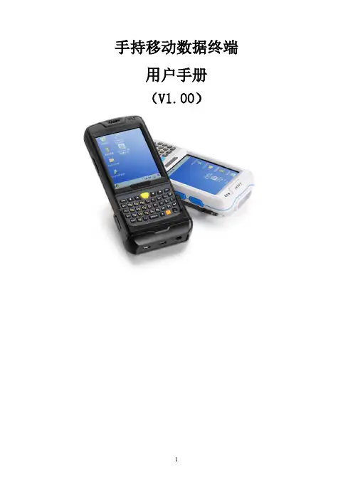
手持移动数据终端用户手册(V1.00)目录第一章产品介绍 (4)1.1 产品技术参数 (4)1.2 外部结构 (7)1.3 键盘说明 (9)1.4 随机配件 (10)1.5 可选配件 (10)第二章使用入门 (12)2.1更换电池 (12)2.2安装TF卡 (13)2.3安装SIM卡 (14)2.4 手柄拆装 (15)2.4 电池充电 (15)2.5 TF卡使用 (16)2.6 休眠与唤醒 (16)2.7 任务栏 (17)2.8桌面 (18)2.9 设备复位 (19)第三章系统设置 (20)3.1Internet选项 (22)3.2PC连接 (24)3.3存储管理器 (25)3.4电源管理设置 (25)3.5键盘属性 (26)3.6区域设置 (27)3.7日期和时间设置 (28)3.8删除程序 (29)3.9输入面板 (30)3.10鼠标 (30)3.11所有者(设备使用者私人信息) (31)3.12网络连接和拨号 (32)3.13系统信息设置 (33)3.14显示及背光设置 (34)3.15音量和声音 (36)3.16拨号设置 (37)3.17证书管理 (37)3.18笔针 (38)3.20 蓝牙管理器 (39)3.21 USB同步修复 (39)3.22 HMS模块电源管理 (40)第四章键盘及输入法 (41)4.1软件盘的使用 (41)4.2输入法 (42)第五章网络连接 (43)5.1WIFI网络连接 (43)5.2GPRS拨号连接 (45)5.2.1 GPRS配置说明 (45)5.2.2 GPRS拨号操作 (50)第六章手持移动数据终端与电脑同步连接 (52)6.1 同步软件安装说明 (52)第七章功能使用 (57)7.1 扫描器的使用 (57)7.2 RFID的使用 (58)7.3 GPS (60)7.4拍照 (60)7.5蓝牙 (61)第八章故障排除 (62)8.1 设备及系统故障 (62)8.2扫描故障 (62)8.3RFID故障 (63)8.4 网络及通讯故障 (63)8.5 WIFI连接故障 (63)8.6 其它故障 (64)第九章保养维护 (64)第一章产品介绍本设备将“ALL IN ONE”的设计理念贯穿其中,它将图像获取、无线通讯、条码扫描、RFID读写器等功能集成一身。


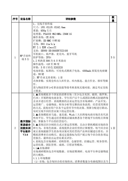
序号设备名称详细参数数量1RF手持终端3台1、无线手持终端尺寸:193.4X119.4X162.6mm重量:650g左右处理器:PXA320@624MHz256M/1G操作系统:CE系统扩展槽:SD/MMC卡槽8G无线:802.11a/b/gBT2.1EDR classII支持:SE950SE4500SR752X480耳机接口、扬声器、麦克风、蓝牙耳机防护等级:IP541.2米跌落500次0.5米滚动操作温度:-10至50度屏幕:3英寸彩色320X320电池容量:标准的:可充电式锂离子电池,4800mAh原装充电座键盘:38键2、RF作业支持系统,1套具体参数:实现仓库出入库作业、库内拣选、盘点作业、移库等操作。
需与物流管理1+X职业技能等级考核系统无缝对接,满足考证及练习要求。
3台2数字国际贸易综合技能实训平台软件V3.01.▲系统模拟多个国家的消费市场(至少包含美国、德国、俄罗斯、巴西)开展跨境电商业务。
学生用户以个人或团队的模式创建跨境企业并进行经营。
系统模拟的企业运营包含市场调研、产品开发、运营推广、仓储物流、财务分析等完整的业务流程,经营采用博弈的方式,系统对用户在各个运营环节中的决策、预算分配进行联动,实时呈现不同经营决策下的运营结果。
2.▲系统模拟亚马逊、速卖通、Wish三大在跨境电商市场具有代表性的平台。
学生通过经营模拟店铺来熟悉各个跨境平台的特点和规则,掌握各个平台的经营技巧。
3.▲系统以回合制的方式计算运营周期,且由计算机模拟市场的各种行为,非角色扮演。
系统提供企业经营的计算模型,每个回合结束后系统根据学生的各项决策对其经营的产品和店铺进行排名,并模拟消费者自动购买,通过定量指标为用户展示每个回合的各项运营报告,最终给出运营结果及评价。
4.系统包含市场调研、采购管理、仓储管理、店铺运营、财务管理、运营结果、团队管理、成绩、日程表等模块。
4.1▲市场调研市场调研模块包含环境数据、市场前期调研、电商平台和仓储物流四大模块。
目录1 手持终端介绍1.1 motorola mc31902 手持终端日常操作2.1 充电方法2.2 开关机、热启动、冷启动3 手持终端无线网络配置3.1 无线网络配置4 手持终端联机pc机4.1 概述4.2 同步工具安装4.3 手持终端中文字库安装5 手持终端键盘功能设置 6手持终端机故障分析1 手持终端介绍1.1 motorola mc3190motorola 讯宝symbol mc3190数据采集终端作为symbol mc3090手持终端的升级替代产品,mc3190是构建于成功的mc3090之上,mc3190采集器系列分为3100批处理盘点机和包含无线局域网wifi的mc3190条码采集器两款。
新的摩托罗拉mc3190系列可为公司内部的按键应用提供成本高效的移动性和用户舒适度。
符合人体工程学的耐用型 mc3190 提供先进的计算能力以及数据采集能力、增强的安全性以及企业级的运动传感能力。
motorola 讯宝symbol mc3190数据采集终端性能参数:数据采集选项-1d 激光扫描仪、1d/2d 成像仪、dpm 内存 (flash/ram)-128mb ram/256 mb flash 或 128mb ram/512mb flash 处理器 (cpu)-marvell pxa320 @ 624 mhz 操作系统 (os)-microsoft windows mobile 6.1 classic, microsoft windows ce 6.0 pro 无线数据通讯:wpan(支持蓝牙技术)-ii 级、v2.1 增强数据速率 (edr), 集成天线wlan-三重模式 ieee? 802.11a/b/g;经过 ccxv4 认证;支持 ipv6;经过 fips140-2 认证(仅限mc3190)线性一维条码扫描器:光学分辨率-最小元素宽度 4 mil 扫描速率-104(+/- 12)次扫描/秒(双向)使用环境:环境密封-ip54(2 类)工作温度--4°至 122° f/-20°至 50° c 跌落规格-在工作温度范围内,多次从 4 英尺/1.2 米高处跌至水泥地面;满足并超过mil-std 810g 滚落规格-根据 iec 68-2-32,在室温条件下,500 次从 1.64 英尺/0.5 米高滚落(1,000次)2.1 充电方法摩托罗拉的每个手持终端都配了两粒电池,同时配了四位充电座。
力英电子科技手持式射频识别读写终端 使用说明书目 录概述.......................................................................2-4第一章 安全注意事项………………………….5-6 第二章 产品各部分名称……………………….7-8 第三章 主要性能参数…………………………9-11第四章 初次使用…………………………......12-13第五章 充电器和电池注意事项......................14-16第六章 手持机操作说明………………..........17-30附:产品保修卡1概 述手持式IC卡移动终端是IC卡系统工程项目重要的配套设备之一。
手持式IC卡移动终端提供方便实用的应用开发平台,丰富的软、硬件接口让用户可以方便、轻松、快捷地构造各种IC卡应用系统。
它具有灵活的上、下载功能,具有高可靠性和通用性,符合相应的国际和国内标准。
手持式IC卡移动终端(以下简称手持机)适用于需要离线处理数据的IC卡信息系统。
典型的应用系统有:驾驶员IC卡管理系统、会展IC卡管理系统、烟草专卖IC卡系统、设备IC卡管理系统、导游IC卡管理系统、公共事业IC卡收费系统、会员IC卡管理系统、物流配送IC卡管理系统、餐饮娱乐IC卡管理系统、社会劳动保险IC 卡管理系统、停车场IC卡收费系统等等。
时尚的外观时尚、简洁的外型及按键设计,辅之以明快的色彩,既赏心悦目,又方便实用;232位超级MCU中央处理单元采用适合于移动及嵌入式应用的32位单片机,集成度高,功能强劲,可快速完成DES等各类复杂加密算法。
大容量存储器标准配备128MB的FLASH处理器,强大的数据存储功能,以及16MB的RAM程序存储器空间更能完美的支持二次开发编程。
另外我们可根据客户的需求专门定制可达2G的数据存储器。
2.4寸超大TFT彩色显示屏采用26万色、320*240像素的2.4寸TFT材质的超大显示屏,带给您更加直观、绚丽的显示画面;可选SAM卡座在配备标准IC卡座的同时,预留SAM小卡座,既能用于金融等需要安全性认证的场合,又可通过使用大容量卡进行数据备份,从而确保系统和数据的安全性;人性化的操作界面采用类似Windows XP的操作界面,让使用者使用起来得心应手,能够迅速的掌握该系统的使3用方法;丰富的通讯接口标准的2.0USB接口,能够快速、精确地与PC 机通讯,进行数据传输;通用开放的二次开放平台独有的32位嵌入式操作系统内核以及标准的C语言编程工具,为客户进行二次开发提供了开放、友好的操作平台。
手持机开发设计说明原来的手持机采用STC51单片机开发的,由于51单片机的种种局限,已经不能适应目前的环境了,想用STM32单片机,加TFT显示,USB接口,COMS摄像等功能。
基本功能如下:手持机功能说明* 刷卡计费功能,并记录消费。
* 查询消费记录。
* 通过232串口,可把消费记录上传到电脑。
* 除车位锁外,还可控制各种其他动作终端,使用灵活。
* 选用名牌微电脑控制芯片和电源控制芯片,工作性能稳定可靠,效率高,功耗低。
* 手持机全中文功能界面显示,操作简单。
* 进入车辆发卡,向卡内写入车辆进入管理区时间。
* 车辆离开刷卡,读取卡内的时间数据。
* 自动计算停车时间,将停车时间XX日XX时XX分显示在液晶屏。
* 自动计算停车应收费用金额。
* 随时可查阅停车收费总金额、进车次数等信息。
* 两级管理,管理级对员工级管理,员工级对进出车辆级管理。
* 填写收费规则,管理级可通过管理卡填写收费规则。
* 清除相关信息,管理级可通过管理卡对停车收费总金额、收费时间等信息一次性清除。
* 时间调整,管理级可通过管理卡进行时间校对。
* 识别和判断内部卡是否有效。
* 电量不足声响及显示提示。
* 随时可将停车收费总金额及收费笔数转存到财务卡内。
* 充电功能。
* 可无线控制:车位锁/道闸/显示屏等。
* 可将收费资料与车牌号码同时上传计算机。
一、手持机管理系统特点1、灵活性:可以在任何两个出入口或一个出入口实现整个停车交易流程。
2、便捷性:安装简易,无需大规模施工,机动性强,无需专用的PC机管理。
3、经济性:系统及设备价格对比同类产品优势明显,具有很高的性价比。
4、智能性:由于利用智能卡和计费机管理,原有的数据收集和整理工作更为简洁准确,避免票款的流失、所需统计数据的准确性大大提高。
5、多样性:手持机+道闸(车位锁)复合使用时,比较适用多车道进出口的管理,可实现进出车辆的分流。
6、服务性:停车管理的反复读写性,可以简化了临时停车证的制作及用户更换带来的麻烦。
WARNINGIF “FAIL” APPEARS ON THE DISPLAY, THECALIBRATION REQUIRED LED (LEFTCOLUMN) REMAINS LIT, OR THECALIBRATED LED (RIGHT COLUMN) DOESNOT LIGHT, THE CALIBRATION PROCESSDID NOT COMPLETE. SHOULD THISHAPPEN, CYCLE THE UNIT POWER ANDTHEN REPEAT STEP 2 ABOVE. IF “FAIL”APPEARS AGAIN, FURTHER TROUBLE-SHOOTING IS REQUIRED.3.Remove the test shunt. The RX Occupancy LED shouldlight. If the RX Occupancy LED fails to light, thecalibration process has failed (refer to the WARNINGabove). Inspect all equipment and connections andrepeat steps 1 & 2. If the calibration fails again,further troubleshooting is required.4.The RX Occupancy LED should light once the testshunt has been removed. Proceed to Receiver andTransceiver Checkout Procedures, Section 7.5.1. Receiver and Transceiver Checkout Procedures1.Scroll down the Main Menu of the Receiver untilINFO appears on the display.2.Momentarily press the MENU Button and release it.“+RX SIG LVL =” appears on the Display.3.Take note of RX SIG LVL. This is the normal receivesignal value. Verify the RX SIG LVL value is >300. Ifnot, set TX LVL to High and perform calibration andcheckout procedures again. If the value remainsbelow 300 after selecting TX LVL=High, select a lowerfrequency where RX SIG LVL value is >300.4.In the WSS containing the transmitter, remove thetransmitter’s signal to the track by disconnecting atransmitter lead from the track surge equipment.5.With the corresponding transmitter disabled, observethe RX SIG LVL. If RX SIG LVL is greater than 20, anunintended signal of like frequency may be present.WARNINGDO NOT PROCEED TO STEP 6 ANDBEYOND UNTIL THE UNINTENDED SIGNALOF LIKE FREQUENCY IS NO LONGERPRESENT (THIS MAY REQUIRE AFREQUENCY CHANGE TO AVOIDUNINTENDED HARMONICS.) THISCONDITION MUST BE RESOLVED.6.Verify that the RX LED found in the Occupancyportion of the face of the unit is de-energized. If theLED remains lit, troubleshoot the unit.7.Restore the Transmitter signal to the circuit byreconnecting the lead in the transmitter’s track surgeequipment.8.Verify that the RX LED found in the Occupancyportion of the face of the unit energizes. If the LEDsfail to light, troubleshoot the unit, re-calibrate, andperform Steps 1 - 7 again.9.Verify proper operation of the track circuitequipment before placing in service in accordancewith railroad or agency procedures and applicableFRA rules.10.Verify proper PSO 4000 operation by observing trainmoves, per railroad or agency policy.11.The system is now ready for operation.NOTEIn the text on this side of the document andon the drawing on the reverse side of thedocument, all references to Section numbersare those section numbers found within theSiemens Phase Shift Overlay 4000 (PSO 4000)Installation and Instruction Manual, SIG-00-07-06.QUICK REFERENCE GUIDEINSTALL PSO 4000TRANSMITTER/RECIEVER MODULESDocument Number SIG-QG-10-03Version A.1The following procedure should be used when installingPhase Shift Overlay 4000 (PSO 4000) Track Circuits utilizingPSO 4000 Transmitter, 7A471 and PSO Receiver, 7A473.WARNINGVERIFY THAT THE PSO 4000TRANSMITTER’S AND RECEIVER’SSOFTWARE, FREQUENCY, AND ADDRESSFORMATS ARE AS SPECIFIED BY THERAILROAD’S OR AGENCY’S APPROVEDWIRING OR INSTALLATION DIAGRAM.FAILURE TO DO SO MAY LEAD TOINCORRECT OR UNSAFE OPERATION OFTHE TRACK CIRCUIT.IF ANY RECEIVER IS CALIBRATED IN POORBALLAST CONDITIONS, IT MUST BE RE-CALIBRATED WHEN BALLAST CONDITIONSIMPROVE.FAILURE TO FOLLOW THE RAILROAD’S ORAGENCY’S APPROVED WIRING ORINSTALLATION GUIDELINES REGARDINGRECEIVER SETTINGS AND CALIBRATIONMAY LEAD TO POSSIBLE UNSAFEOPERATION OF THE TRACK CIRCUIT.AFTER CALIBRATION, VERIFY THAT THETRACK CIRCUIT DE-ENERGIZES WHEN THETRACK CIRCUIT IS SHUNTED WITH THEAPPROPRIATE CALIBRATION RESISTANCE(0.06, 0.2, 0.3, 0.4, OR 0.5 OHMS). FAILURETO DO SO MAY LEAD TO INCORRECT ORUNSAFE OPERATION OF THE TRACKCIRCUIT.FOLLOWING INSTALLATION OR AFTERANY RECEIVER MENU CHANGES HAVEBEEN MADE, RECALIBRATE THE RECEIVERAND TEST FOR PROPER OPERATION PERTHE REQUIREMENTS SPECIFIED IN TABLE7-2 AND TABLE 7-3 OF SIG-00-07-06, PSO4000 I & I MANUAL.Perform the following steps to install the PSO 4000 units:1.Install and connect all PSO equipment in the WaysideSignaling Station (WSS) per the railroad’s or agency’sapproved wiring or installation diagram.2.Connect all required wiring per the railroad’s oragency’s approved wiring or installation diagram.3.Prior to beginning programming, verify LEDfunctionality using the *CHECK LED portion of theTEST menu per Section 5.2.7.2. If any LED fails to lightfollowing test, replace the unit.4.Program each unit by performing Set to Default. Thenproceed through the setup (SETP) menu to programeach unit per the railroad’s or agency’s approvedwritten instructions.With each unit properly installed and programmed perwritten instructions, calibrate the receiver (RX) as follows:1.When the track ballast is good, connect a track testshunt (hardwire, 0.06-ohm, 0.2-ohm, or as required)across the track at the receiver track connections.When the ballast is poor, connect the shunt acrossthe track at a point 30 feet beyond the receiver trackconnections. Verify solid connections of the shunt toeach rail.2.Scroll down the Main Menu until CAL appears on thedisplay. Then:•Press the MENU Button for two (2) seconds untilRX CAL appears.•Hold the MENU Button down until the release(REL) message appears. Release the MENU Buttonimmediately once the release (REL) messageappears.•As soon as the MENU button is released, thearmed (ARMD) message appears. Immediatelypress and release the MENU Button as soon asthe ARMD message appears. This starts thecalibration process. If the MENU Button is notpressed within two (2) seconds, the calibrationprocess cancels and the calibration process mustbe restarted.•*RX CAL flashes during the calibration process.•PASS or FAIL appears for two (2) seconds whencalibration is complete. When PASS appears,continue to Step 3. If FAIL appears, theCALIBRATION REQUIRED LED remains lit-2--8--7- Copyright © 2010-2014 SiemensAll Rights ReservedPSO 4000 TRANSMITTER, 7A471PSO 4000 RECEIVER, 7A473 Array-3- -4- -5- -6-。
AgilentV3500A Handheld RF Power Meter Data SheetThe first palm-sized power meter from Agilent Technologies that delivers high lab quality RF power measurements for installation and maintenance or R&D lab environmentsWhy Agilent’s Power Meters and Sensors?Reliable, high-performing solutionsEvery power meter and sensor from Agilent consistently delivers great results.A sure investment for many years to comeCode-compatibility between power meters reduces the need for re-coding. Notonly that, all Agilent power meters are backward-compatible with most legacypower sensors.One specific application: One right solutionAgilent offers a wide selection of power meters and sensors for practicallyall application needs—wireless communications, radar pulse measurements,component test and more.Global network supportNo matter where you are, Agilent is committed to giving you the 24-hour sup-port you need regarding our products, applications or services.Agilent’s power meters have long beenrecognized as the industry standard forRF and microwave power measurements.Compact, Portable Solutions for Today’s RF Power MeasurementsFor production testingFor R&D and design verificationFor installation andmaintenanceAssociated with mobile phones and infrastructure, wireless sensors and transceivers, and WiMAX™, WLAN, RFID, mobile radio, Zigbee, and Bluetooth ® devices• Compact build saves rack space • Simple set-up and usage• Wide dynamic and frequency range• Compact build saves bench space • Simple set-up and usage• Wide dynamic and frequency range • High accuracy• Advanced troubleshooting of designs with built-in backlight display for easy readings and data recording• Integrated power sensor eliminates the need to carry separate sensor • Lightweight and rugged • Truly portable (with AA batteries)• Wide dynamic and frequency range • Quick and easy testing with built-in backlight displayIntroducing the New Member of the Power Meter Family – the Agilent V3500AThe Agilent V3500A handheld RF power meter is a compact, portable instrument that makes lab quality RF power measurements in both field and R&D laboratory environments. With an absolute accuracy up to±0.21 dB, a wide frequency range of 10 MHz to 6 GHz, and measurement range of –60 dBm to +20 dBm, the V3500A is suitable for a wide variety of RF measurement applications. Itsbuilt-in power sensor eliminates theneed for users to carry both an instru-ment and a separate sensor module,and the same sensor is used whenduplicating tests or measurementsfor better repeatability. Truly portable,the V3500A fits easily into your handor a toolkit and optional loop holstercarrying case with shoulder strapis also available to fit your need. Tooptimize flexibility, it’s capable ofdrawing operating power from batter-ies, an AC-DC converter module, or acomputer via the USB interface. Withits features and very attractive price,the V3500A truly redefines superiorvalue.High accuracy in both the laband fieldWhether it’s used in the field or onthe factory floor, the Agilent V3500Amakes lab quality RF measurementsquickly and easily. Its absoluteaccuracy up to ±0.21 dB,enablesmore precise characterization ofdevices, tighter test limits, and moreaccurate fixture calibration. In thelaboratory, it can be used as an RFpower data-logger. Using normal orhigh speed mode, it easily capturesand transfers data to your personalcomputer through its built-in USBinterface (cable supplied), allowingfor trend or drift analysis. Despite itssmall package, the V3500A providesoutstanding accuracy on the bench,replacing much larger and moreexpensive instrumentation.Convenient utilitiesThe V3500A incorporates severalhandy and practical utilities thatmake it easier than ever to attain highquality RF measurements with thishandheld instrument. Compensatethe display reading for any losses orgains between the location wherethe level of power is desired and theactual point where the power can bemeasured. Typically the compensationwill be required for cable loss. Therelative offset factor can be as largeas 99.99 dB, and the offset can beprogrammed with a resolution of0.01 dB. A number of averaging val-ues can be used when the signal youwant to measure varies significantlywith time. A hold command saves ameasurement that is made in a hardto reach area until the instrumentcan be retrieved. A backlight can beilluminated when making measure-ments in poorly lit areas. To maximizebattery life, the V3500A can be set upto turn off the backlight or the instru-ment entirely after a specific period oftime. Once the instrument utilities aresetup in the manner you prefer, theinstrument state can be saved for thenext use.Take a Closer LookRF connectorIn the RF world, cables are often equipped with N-connectors and SMA connectors. N-con n ectors are commonly used on test instru-mentation, because they are rugged, can handle high powers, and perform well up to about 18 GHz.This section contains information about how to make RF signal connections to the Type N male RF connector (50 Ω characteristic impedance—refer to Figure 1) of the V3500A for power measurement.Connection for a power measurementNOTE : When connecting the Type N connector of the V3500A to a Type N female connector for a power measurement, observe the following proper practice for tightening the connection.Figure 1. Signal connectionType N male connector nutBuilt-in backlight display ensures visibility in dark locations Body – small and lightweight build to fit into your hand “Zeroing” key function allows a more accurate measurement at low power levelsArrow keys for menu selection and settingsFrequency keys for rapid setting of input signal“Hold” key allows saving of measurement that made in hard to reach area until theinstrument can be retrievedWhile holding the body of the power meter in one hand, turn the Type N male connector nut to tighten the connection (do not turn the body of the V3500A). Continue to do so until the connection is hand-tight. It is important to turn the nut of the connector rather than the body of the power meter when tightening the connection.USB portNOTE: The term USB (UniversalSerial Bus) is used in this data sheet. USB is simply another term for the Universal Serial Bus.The power meter has a USB 2.0interface with a USB type Mini-B port (refer to Figure 2). The V3500A can be remotely programmed over this USB interface. In addition to programming, the V3500A can be powered by the USB. With the USB connected and providing power, and the optional external power disconnected, the V3500A will be powered from USB regardless of whether batteries are present.NOTE: The interface is USB 2.0 com-patible, but with an interface speed of 12 Mbps.External power connectorThe power connector provides a connection for the optional external power supply (refer to Figure 2). If the external power supply is connected, the V3500A will be powered by the external supply, regardless of whether USB power or batteries are present.CAUTION: Only connect the optional external power supply (V3500A-PWR) to this connector. Instrument dam-age may result if improper power is applied.Battery powerThe V3500A can also be powered by two AA batteries. If installed, the batteries will power the V3500A only if the external power supply and USBare not connected.Figure 2. USB and power connectorMini-B port for connection to PC connector (use with optional power supply)SpecificationsThe following specifications are based on performance at a temperature of 23 °C ± 5 °C unless stated otherwise. Category SpecificationsFrequency range10 MHz to 6 GHzPower range–60 dBm to +20 dBmMaximum power+23 dBm, 5 VDCPower accuracy Frequency range 10 MHz to 3.75 GHz 3.75 GHz to 6 GHz Frequency range 10 MHz to 3.75 GHz 3.75 GHz to 6 GHz Frequency range 10 MHz to 3.75 GHz 3.75 GHz to 6 GHz Frequency range 10 MHz to 3.75 GHz 3.75 GHz to 6 GHz Frequency range 10 MHz to 3.75 GHz 3.75 GHz to 6 GHz Frequency range 10 MHz to 3.75 GHz 3.75 GHz to 6 GHz At 23 °C ±5 °C1+20 dBm to +6 dBm±0.23 dB±0.20 dB+6 dBm to –9 dBm±0.26 dB±0.40 dB–9 dBm to –29 dBm±0.18 dB±0.19 dB–29 dBm to –39 dBm±0.22 dB±0.25 dB–39 dBm to –50 dBm±0.36 dB±0.39 dB–50 dBm to –55 dBm±1.37 dB±1.81 dBAt 0 °C to 50 °C+20 dBm to +6 dBm±0.33 dB±0.44 dB+6 dBm to –9 dBm±0.33 dB±0.55 dB–10 dBm to –29 dBm±0.29 dB±0.34 dB–30 dBm to –40 dBm±0.32 dB±0.44 dB–39 dBm to –50 dBm±0.48 dB±0.65 dB–50 dBm to –55 dBm±1.47 dB±1.97 dBLinearity–40 dBm to +6 dBm –50 dBm to –40 dBm –50 dBm to –55 dBm At 23 °C ±5 °C±0.1 dB±0.4 dB±1.0 dBAt 0 °C to 50 °C±0.2 dB±0.5 dB±1.1 dBNoise floor At 0 °C to 50 °C–61 dBmSpeed Normal ~2 readings per second (> –30 dBm approximately)~1 readings per second (≤ –30 dBm approximately)High-speed ~23 readings per second (> –30 dBm approximately)~10 readings per second (≤ –30 dBm approximately) 1. Customer spec after warm up time of 30 minutesX = (x,f) + K(=2) · δ(x,f) + ΔE (x,f[18 ° – 28 °C]) + μwhereX is mean of the data taken in the frequency range stated (x,f).δ is standard deviation of the data taken in the frequency range stated (x,f). x is measured value at test frequencies.f is frequency range over which data was taken for specification.μ is measurement uncertainty.ΔE is change associated temperature variation.18 ° – 28 °C is the statistics generated separately at these temperatures and larger statistical value used in setting spec.SWR performance for different frequency bandFrequency bandSWR (0 °C to 50 °C)10 MHz to 3.75 GHz 3.75 GHz to 6 GHz1.131.220100020003000Frequency (MHz)4000500060001.181.161.141.121.101.081.061.041.021S W R (x :1)Typical SWR performancePower (equipped with auto-shutoff)• Two 1.5 V alkaline AA batteries (typical battery life: 17.5 hours1 with low battery indicator• USB interface cable (Standard-A to Type-B)2• Optional external DC power supply3 (V3500A-PWR)Display• 4 digits with backlight and auto-shutoff feature• Hold feature—most recent reading is shown on the display and is no longer updated Connector• USB 2.0 interface with a mini-B USB connector4• Type N male RF connector (50 Ω characteristic impedance)Operating environment• At 0 ° to 50 °C• Up to 80% RH for temperature up to 35 °C, non-condensing• Altitude up to 2,000 metersStorage compliance• –10 °C to 70 °C• Non-operating maximum humidity: 90% at 65 °C, non-condensingEMC compliance Certified with• IEC 61326-2-1:2005/EN 61326-2-1:2006• Canada: ICES-001:2004• Australia/New Zealand: AS/NZS CISPR11:2004Pollution degree Pollution Degree 2Dimensions (W × H × D)79 mm × 134 mm × 49 mm (without N-connector)Weight0.5 kgWaranty• One year for the V3500A Handheld RF Power Meter• Three months for the standard shipped and optional accessoriesCalibration cycle One year1. Typical battery life was measured in the default conditions from the factory at 500 MHz with backlight off and no USB communications. Withbacklight on, typical battery life is 2.5 hours.2. With the USB connected and providing power, and the optional external power disconnected, the V3500A will be powered from USB regardless ofwhether batteries are present.3. If the external power supply is connected, the V3500A will be powered by the external supply, regardless of whether USB power or batteries arepresent.4. The interface is USB 2.0 compliant but with an interface speed of 12 Mbps.Ordering InformationAgilent V3500A Product Reference CD-ROM Accessories, calibration and documentation optionsExternal power supplyV3500A-SHL Holster carry case with shoulder strapV3500A-CA1USB cable type A to Mini-B, 2.5 meter (8.2 feet) V3500A-ABA English User’s GuideV3500A-0B1English User’s Guide and Installation GuideV3500A-0BW English Service GuideV3500A-ABJ Japanese User’s GuideV3500A-AB2Simplified Chinese User’s Guide/find/V3500ABluetooth and the Bluetooth logos are trade-marks owned by Bluetooth SIG, Inc., U.S.A. and licensed to Agilent Technologies, Inc.WiMAX is a trademark of the WiMAX Forum.AdvancedTCA ® Extensions for Instrumentation and Test (AXIe) is an open standard that extends the AdvancedTCA for general purpose and semiconductor test. Agilent is a founding member of the AXIe consortium.LAN eXtensions for Instruments puts the power of Ethernet and the Web inside your test systems. Agilent is a founding member of theLXI consortium.PCI eXtensions for Instrumentation (PXI) modular instrumentation delivers a rugged, PC-based high-performance measurement and automation system.Three-Year Warranty/find/ThreeYearWarrantyBeyond product specification, changing the ownership experience.Agilent is the only test and measurement company that offers three-year warranty on all instruments, worldwide.Agilent Assurance Plans/find/AssurancePlansFive years of protection and no budgetary surprises to ensure your instruments are operating to specifications and you can continuallyrely on accurate measurements./qualityAgilent Electronic Measurement Group DEKRA Certified ISO 9001:2008 Quality Management SystemAgilent Channel Partners/find/channelpartnersGet the best of both worlds: Agilent’s measurement expertise and product breadth, combined with channel partner convenience.For more information on AgilentTechnologies’ products, applications or services, please contact your local Agilent office. The complete list is available at:/find/contactus AmericasCanada (877) 894 4414 Brazil (11) 4197 3600Mexico 01800 5064 800 United States (800) 829 4444Asia PacificAustralia 1 800 629 485China 800 810 0189Hong Kong 800 938 693India 1 800 112 929Japan 0120 (421) 345Korea 080 769 0800Malaysia 1 800 888 848Singapore 180****8100Taiwan 0800 047 866Other AP Countries (65) 375 8100Europe & Middle EastBelgium 32 (0) 2 404 93 40 Denmark 45 45 80 12 15Finland 358 (0) 10 855 2100France 0825 010 700* *0.125 €/minute Germany 49 (0) 7031 464 6333 Ireland 1890 924 204Israel 972-3-9288-504/544Italy 39 02 92 60 8484Netherlands 31 (0) 20 547 2111Spain 34 (91) 631 3300Sweden 0200-88 22 55United Kingdom 44 (0) 118 927 6201For other unlisted countries:/find/contactus(BP-09-27-13)Product specifications and descriptions in this document subject to change without notice.© Agilent Technologies, Inc. 2013Published in USA, December 17, 20135990-5483EN。
专用通信手持终端设计与实现范文现如今,手持终端的功能需求不断增多,为了更好的满足功能使用需要,应利用先进技术开发专用手持台,这对生产作业顺利推进、设计经验积累有重要意义。
本文这一论题具有探究必要性,有利于优化通信手持终端设计质量,同时,更好的满足设计需要,丰富设计经验。
一、需求分析(一)技术需要综合考虑工作湿度、温度等因素,其中,湿度要求在91%~95%,温度要求在-24℃~53℃,同时,参照《移动通信调频无线机环境要求和试验方法》——GB/T15844.2-1995开展等级设计;掌握电气特性,合适调节音频输出功率,确保扬声器音频输出功率在0.5W范围内,并且载波功率不超过1.8W;供电保证24小时,其中,手持台工作时间保证8小时,电池电能供给情况影响手持台信号接收效果;手持台实际使用的过程中,合理设计外观尺寸,坚持功能一体化设计原则,使其满足易操作、耐用、防尘等要求[2]。
(二)功能需要通信手持终端应具备收据接收、转发功能,即借助GSM-R网络完成数据信息顺利传送,以此满足无线数据便捷传输需要;具备语音通话功能,支持呼叫、接听等操作;具备参数设置功能,合理设计身份码、优先级别等参数;具备声音提醒功能,手持终端传输指令的过程中,适当的语音提示能够显示信号有效性,并且工作人员应根据信号提示注意程序操作的合理性,以免无线通道占用,大大提高作业安全性;手持台操作者多为生产作业员工,员工工作环境相对恶劣,因此,手持终端应保证夜间照明稳定性和持续性;一旦系统出现无法撤销的错误,手持终端支持重新启动,确保终端作业顺利开展[2]。
二、ARM处理器下专用通信手持终端设计与实现(一)软件设计软件设计主要包括两方面,第一方面即总体设计,第二方面即程序设计。
对于总体设计,根据单片机设计思想制定设计方案,在使用界面以及操作功能方面适当改良,开发平台最终选用嵌入式Linux操作系统。
操作系统具体四方面,分别嵌入式Linux内核移植、应用程序开发、引导程序制定、文件系统开发,其中,应用程序开发的过程中,根据QTE 为根底的免桌面管理程序为设计思路,这对设计程序简化、运行速度提高有促进作用;引导程序的作用即系统初始化操作、转移控制权于操作系统,同时,支持参数设置以及输送,它具体包括两种类型,分别为通用引导程序和专用引导程序。
Technical SpecificationSpecificationsRF UpstreamFrequency Range (MHz)5 to 85 (5 to 65 with Software Release 1.0)ModulationQPSK, 8 QAM, 16 QAM, 32 QAM, 64 QAM (No 8 QAM Support in Software Release 1.0)Channel TypeTDMA, ATDMA, TDMA/ATDMA, SCDMA (No SCDMA Support in Software Release 1.0)Data Rate (Mbps) (Max.)30.72 per channel RF Input Level (dBmV)-16 to +29Frequency Resolution (KHz)< 1Symbol Rate (Ksym/sec)160, 320, 640, 1280, 2560, 5120Bandwidth per Channel (MHz)0.2, 0.4, 0.8, 1.6, 3.2, 6.4PhysicalPower-48 V DC (-40 to -72 V DC )Power Consumption170 W nominal and TBD W max at -48 V DC , 77°F (25°C)Operating Temperature :Short Term °F (°C)+23 to +131 (-5 to +55)Long Term °F (°C)+41 to +104 (+5 to +40)Storage Temperature °F (°C)-40 to +158 (-40 to +70)Operating Humidity (Min.-Max.)5 to 85% (Non condensing)Dimensions (H x W x D) in. (cm)13.8 x 1.2 x 17. 8 (35.0 x 3.0 x 45.3) Weight lbs. (kg)approx. 4.6 (2.1)Support with Software Release 1.0 (Partial Feature List)Upstream CAM Flexible Mapping of Upstream Channels to RF Connectors Up to 12 Upstream Channels per RF Connector 24 RF (MCX) Connectors per Physical Interface Card (PIC)Up to 5+1 RF Sparing BPI/BPI+ Support DOCSIS ®3.0 Multicast IP Video Support via IGMPv3 Control IPv6 Features Cable modem management Dual-Stack CPE IS-IS Routing with Multi-topology support Cable Source Verify with DHCP Lease Query Route Injection (RI) for DHCPv6 Prefix Delegation OSPFv3Prefix Stability Distribute Lists TFTP Enforce / Dynamic Shared Secret DS and US Subscriber Management FiltersPolicy-Based RoutingDOCSIS 3.0 24 Channel Bonding (Downstream)DOCSIS 3.0 Four Channel Bonding (Upstream)IS-IS, BGPv4PacketCable™ Multimedia SupportDynamic Cable Modem Load BalancingSII Lawful Intercept (RFC 3924)802.1Q VLAN taggingExtended ACLs & Named ACLsSecure Shell v2 (SSHv2)DOCSIS PingDHCP Relay Agent (Option 82)DNS ClientTFTP Enforce and Dynamic Shared SecretBSoD L2 VPNBPI+ EnforceIPDR/SPContinued on the next page…E6000™Converged Edge Router (CER)Upstream Cable Access Module (UCAM) Technical SpecificationsARRIS Technical SpecificationsOrdering InformationPart Number DescriptionUCAM Kits799008E6000 CER 48 US UCAM Kit (Active) -1 UCAM, Active UCAM PIC, and 48 DOCSIS US Licenses801026E6000 CER 48 US UCAM Kit (Spare) -1 UCAM, Spare UCAM PIC, and 48 DOCSIS US Licenses802221E6000 CER 96 US UCAM Kit (Active) -1 UCAM, Active UCAM PIC, and 96 DOCSIS US Licenses802222E6000 CER 96 US UCAM Kit (Spare) -1 UCAM, Spare UCAM PIC, and 96 DOCSIS US LicensesLicense Bundles801062E6000 CER 48 DOCSIS US License BundleMaintenance Plan (required)801169E6000 Software Maintenance –Phone Plus GoldSpecifications are subject to change without notice.The capabilities, system requirements and/or compatibility with third-party products described herein are subject to change without notice. ARRIS, the ARRIS logo,Auspice®, BigBand Networks®, BigBand Networks and Design®, BME®, BME 50®, BMR®, BMR100®, BMR1200®, C3™, C4®, C4c™, C-COR®, CHP Max5000®,ConvergeMedia™, Cornerstone®, CORWave™, CXM™, D5®, Digicon®, E6000™, ENCORE®, EventAssure™, Flex Max®, FTTMax™, HEMi®, MONARCH®, MOXI®, n5®,nABLE®, nVision®, OpsLogic®, OpsLogic® Service Visibility Portal™, Opti Max™, PLEXiS®, PowerSense™, QUARTET®, Rateshaping®, Regal®, ServAssure™, ServiceVisibility Portal™, TeleWire Supply®, TLX®, Touchstone®, Trans Max™, VIPr™, VSM™, and WorkAssure™ are all trademarks of ARRIS Group, Inc. Other trademarks andtrade names may be used in this document to refer to either the entities claiming the marks and the names of their products. ARRIS disclaims proprietary interest inthe marks and names of others. © Copyright 2013 ARRIS Group, Inc. All rights reserved. Reproduction in any manner whatsoever without the express writtenpermission of ARRIS Group, Inc. is strictly forbidden. For more information, contact E6000UCAM_TS_20FEB13。
手持终端设计需求说明书一、RF收货操作1、RF收货1供应商到达后,收货人员先在系统中打印出定单的收货预检单,同时收货人员指导供应商卸货码盘(要求码盘尽量按照一个物理盘只对应一个品项),打开RF收货模块,输入预检单号,核对无误后进行下一步。
2收货人员进行收货操作,卸货的同时收货员可以对货品进行收货操作。
收货操作如下:(1)输入预检单号(2)扫描托盘条码(3)扫描商品条码(检查当前商品的信息是否准确)(4)输入商品的生产日期(检查商品的生产日期是否符合要求)(5)输入该托盘的实际数量,按照整箱和零散分别输入。
(6)出现错误可以输入托盘号选择重输,则该托盘当前已输入数据清空,托盘释放。
(7)选择下一托盘,继续收货。
(8)若该单已收完,选择结束收货。
或者当前已到的商品收完,选择暂停收货。
界面显示(带冒号的为输入项或者扫描输入项,其他为查询显示项)预检单号: 普通收货或者越库收货(根据预检单显示)托盘号:取消或者重收(按钮)商品条码:商品名称码盘规格包装件数生产日期:验收标准本次已收的托盘数收货数量整箱:零散:(按钮)结束收货托盘查询暂停收货退出2、托盘查询(1)输入或者扫描托盘码,调出该托盘的商品信息,若未上架或者未入库,可以选择取消托盘,重新收货,若已进行入库处理,则只是查询。
界面显示(带冒号的为输入项或者扫描输入项,其他为查询显示项)托盘号:当前货品码盘规格当前数量(按钮)取消托盘(若只能查询,则为灰色)退出3、商品上架(1)扫描托盘码(2)查询出当前托盘的货物信息。
出现建议存储货位。
(3)输入建议存储货位,弹出验证码,输入当前存储货位的验证码,确认上架。
(4)若出现当前储位出错,则选择上架异常。
重新产生下一个建议储位。
并把当前的上架异常传回业务系统,同时把当前的异常在异常表里记录。
界面显示(带冒号的为输入项或者扫描输入项,其他为查询显示项)托盘码:当前货品码盘规格当前数量建议储位确认储位输入:校验码:(按钮)上架上架异常退出上架异常界面托盘码当前货品码盘规格当前数量储位输入:校验码:(按钮)生成下一建议储位确认当前退出二、RF越库收货1、越库收货供应商到达后,收货人员先在系统中打印出定单的越库收货预检单,同时收货人员指导供应商卸货码盘(要求码盘尽量按照一个物理盘只对应一个品项),打开RF越库收货模块,输入越库的预检单号,(1)输入越库预检单号(2)扫描托盘条码(3)扫描商品条码(检查当前商品的信息是否准确)(4)输入商品的生产日期(检查商品的生产日期是否符合要求)(5)输入该托盘的实际数量,按照整箱和零散分别输入。
(6)出现错误可以输入托盘号选择重输,则该托盘当前已输入数据清空,托盘释放。
(7)选择下一托盘,继续收货。
(8)若该单已收完,选择结束收货。
或者当前已到的商品收完,选择暂停收货。
界面显示(带冒号的为输入项或者扫描输入项,其他为查询显示项)预检单号: 越库收货(根据预检单显示)托盘号:取消或者重收(按钮)商品条码:商品名称码盘规格包装件数生产日期:验收标准本次已收的托盘数收货数量整箱:零散:(按钮)结束收货托盘查询暂停收货退出2越库的托盘查询(1)扫描托盘码,调出该托盘的商品信息,若未上架或者未入库,可以选择取消托盘,重新收货,若已进行入库处理,则只是查询。
界面如下(带冒号的为输入项或者扫描输入项,其他为查询显示项)托盘号:当前货品码盘规格当前数量(按钮)取消托盘(若只能查询,则为灰色)退出三、移库补货操作1、总体界面包括三部分:移库补货,非指令移库,非指令补货。
界面显示:“移库补货”,“非指令移库”,“非指令补货”,“退出”四个按钮。
点击可以分别功能专属界面或退出返回上级菜单。
2:移库和常规补货:兼作移库和补货两种功能,移库完成的是货位间货品的移动,补货侧重于主业务每天的整箱补货,从储位到拣货位的货品移动。
补货以拣货位通道行进方向为顺序。
RF可以分区域的随时查找任务,完成补货操作。
界面显示:移、补:单选按钮,如果是补货,选中‘补’;如果是移库,选中‘移’。
区域号:自动显示移出货位:自动显示商品编码:自动显示规格:自动显示数量:自动显示批次:自动显示移入货位:自动显示“提交”、“退出”“移出异常”,“移入异常”两按钮移出异常:停下来,检查原因,同时把当前的异常在异常表里记录。
移入异常:停下来,检查原因,同时把当前的异常在异常表里记录。
3、非指令移库:直接针对货位库存操作,移出移入对应货位库存增减。
界面显示:移出货位:输入移入货位:输入有“提交”,“退出”两个按钮。
4、非指令补货:补充正常补货之外的偶然操作。
任务也是发过来的界面显示:移入货位:先自动显示,可调整。
移出货位:自动显示商品编码:自动显示商品名称:自动显示商品规格:自动显示商品批次:自动显示件数:自动显示,可调整。
下面是:“提交”,“退出”两按钮。
四、验货复核1、总体界面包括两部分:周转箱箱内验货复核和集货区整件验货复核。
界面显示:“周转箱内复核”,“集货区复核”,“退出”三个按钮。
点击可以分别进入功能专属界面或退出返回上级菜单。
2、周转箱内验货复核:复核可以随机抽查,也可以逐箱复核,调出一个周转箱内的所有商品信息,用RF逐个的扫描箱内的商品,填加数量,保存时与原有信息进行比对。
如果有差异的,把差异记录到差异表里。
复核结束后,标志变为已复核。
复核的环节里要记录合箱过程,可以把一个箱内的商品全部转移到另一箱中,该箱记录两个箱号。
修改门店的总箱数。
界面显示:周转箱号:输入或扫入“获得信息”按钮,调出周转箱内的所有商品显示在下面。
“随机抽查”复选框。
下面是“应有的商品”:明细显示商品条码:可扫入“允许输入”复选框。
数量:可输入下面是“扫描完成保存”,“退出”两按钮。
3、集货区验货复核:复核一个作业号下的门店下的整体件数及周转箱数。
出现差异记录到差异表里,查找原因,做订正,标志变为已集货复核。
界面显示:拣货单号:输入或可调出。
根据拣货单号显示调出信息。
配货作业号:自动显示拣货单号:自动显示拣货分区:自动显示门店:自动显示门店及门店简称是否复核过:否状态:显示标志进行状态下面是复核要回填的区域整箱数:自动显示复核整箱:填入周转箱数:自动显示复核周转箱数:填入下面是“提交”,“退出”两按钮。
五、盘点界面显示及说明:盘点单号:输入盘点单号。
(输入后要和系统中正在进行的盘点单号进行比较,如果没有找到该单号,提示:“盘点单号不存在或已结束。
”)盘点范围:显示项,下拉列表,不可修改。
输入盘点单号后,按顺序显示该盘点单号尚未盘点的货位编码。
货位编码:扫描货位编码。
(盘点单号+货位编码与T_pdmx比较,如果没有找到记录,提示:“此货位不在此次盘点范围内或已结束。
”,出现提示后盘点人员可终止该货位的盘点,也可以继续盘点)商品条码:扫描商品条码。
(从商品信息中查询商品名称和商品规格显示到界面)生产日期:查看商品生产日期,手工输入。
(是否先显示出来,于实际不符可以修改)每件数量:查看商品每件数量,手工输入。
(是否先显示出来,于实际不符可以修改)实盘件数:盘点人清点托盘上商品整件数量,手工输入。
实盘零散:如果有非整件商品,手工输入数量。
盘点员:进入程序后自动将登陆人员信息填入。
保存按钮:根据盘点单号+货位编码+商品条码+生产日期+每件数量修改T_pdmx中的Pdjs、pdls,计算pdsl(pdjs*mjsl+pdls);如果没有找到记录,盘点异常,将T_pdmx中该货位记录的clbz修改为E,同时将实际盘点信息插入T_pdmx。
清屏按钮:清空当前页面内容。
退出按钮:退出盘点程序界面。
注:所有查询和按钮主要代码要使用存储过程实现。
六、RF登录及权限操作1:登录输入用户名及密码,可以进入到RF主界面。
登录界面界面显示。
用户名:输入密码:输入下面是“进入”,“返回”。
主界面页面显示:按钮。
“系统管理”(“菜单设置”,“权限设置”)——管理员可以看到。
“收货”(“正常收货”,“越库收货”)“上架”“移库补货”(“非指令移库”,“非指令补货”)“验货复核”(“周转箱内验货复核”,“集货区验货复核”)“盘点”“退出”点击分别进入下级菜单或功能专属界面或退出RF操作。
2、系统管理包括两部分:菜单设置和权限设置。
界面显示:“菜单设置”,“权限设置”,“退出”三个按钮。
点击可以分别进入功能专属界面或退出返回上级菜单。
2、菜单设置以层级树的形式显示菜单结构,可以拖拽调整,增删,修改。
3、权限设置可以针对用户或用户组的形式设置相应的菜单使用权限。
界面显示:左侧用户及用户组右侧菜单以层级树的结构显示可以复选下面有“保存”,“退出”按钮。
七、手持离线的补充说明目前手持设备离线操作主要涉及收货部分,包括正常收货和越库收货。
离线操作主要为。
出现断网现象以后,把手持设备带到微机室,把对应收货需要的数据下传到手持设备中。
维持的界面仍为正常的收货界面,需在界面的右上方显示断网提示。
1.需要下传的结构为,t_spml(商品表),t_hzxx(货主信息),t_yjmx(预检明细),t_ykyjmx(越库预检明细),t_hzghdw(货主供货单位),t_spbzggml(商品的摆盘明细),2.需要传回的结构为,t_yjmx(预检明细,t_ykyjmx(越库预检明细),t_tpmx(托盘明细)目前的结构包括了正常和越库收货的具体表结构是需要互相传递的。