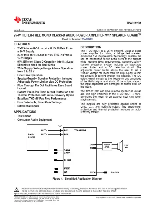
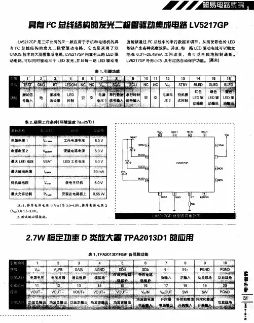
TPA2031D1YZFR,TPA2031D1YZFT,TPA2013D1RGPRG4,TPA2013D1YZHR,TPA2013D1YZHR, 规格书,Datasheet 资料
- 格式:pdf
- 大小:1.07 MB
- 文档页数:30
FEATURESAPPLICATIONSDESCRIPTIONGPIO2.7-W CONSTANT OUTPUT POWER CLASS-D AUDIO AMPLIFIER WITH INTEGRATEDBOOST CONVERTER•Cell Phones •High Efficiency Integrated Boost Converter (Over 90%Efficiency)•PDA •GPS• 2.2-W into an 8-ΩLoad from a 3.6-V Supply •Portable Electronics• 2.7-W into an 4-ΩLoad from a 3.6-V Supply •Operates from 1.8V to 5.5V•Efficient Class-D Prolongs Battery LifeThe TPA2013D1is a high efficiency Class-D audio •Independent Shutdown for Boost Converter power amplifier with an integrated boost converter.It and Class-D Amplifierdrives up to 2.7W (10%THD+N)into a 4Ωspeaker.•Differential Inputs Reduce RF Common Noise With 85%typical efficiency,the TPA2013D1helps extend battery life when playing audio.•Built-in INPUT Low Pass Filter Decreases RF and Out of Band Noise SensitivityThe built-in boost converter generates the voltage rail •Synchronized Boost and Class-D Eliminates for the Class-D amplifier.This provides a louder Beat Frequenciesaudio output than a stand-alone amplifier connected directly to the battery.It also maintains a consistent •Thermal and Short-Circuit Protectionloudness,regardless of battery voltage.Additionally,•Available in 2.275mm x 2.275mm 16-ball the boost converter can be used to supply external WCSP and 4mm x 4mm 20-Lead QFN devices.PackagesThe TPA2013D1has an integrated low pass filter to •3Selectable Gain Settings of 2V/V,6V/V,and improve RF rejection and reduce out-of-band noise,10V/Vincreasing the signal to noise ratio (SNR).A built-in PLL synchronizes the boost converter and Class-D switching frequencies,thus eliminating beat frequencies and improving audio quality.All outputs are fully protected against shorts to ground,power supply,and output-to-output shorts.Please be aware that an important notice concerning availability,standard warranty,and use in critical applications of Texas Instruments semiconductor products and disclaimers thereto appears at the end of this data sheet.PRODUCTION DATA information is current as of publication date.Copyright ©2007,Texas Instruments IncorporatedProducts conform to specifications per the terms of the Texas Instruments standard warranty.Production processing does not necessarily include testing of all parameters.V CC FB S W S W V C C O U TV C C I NS D bI N +I N –P G N DP G N DSDdV DD P G N DRGP (QFN) Package(Top View)TPA2013D1RGPGAIN AGND VOUT–VOUT–VOUT+VOUT+VOUT+YZH (WCSP) Package(Top View)TPA2013D1YZHTPA2013D1SLOS520–AUGUST 2007These devices have limited built-in ESD protection.The leads should be shorted together or the device placed in conductive foam during storage or handling to prevent electrostatic damage to the MOS gates.BOOST CONVERTER TERMINAL FUNCTIONSTERMINALI/O DESCRIPTIONNAME QFN WCSP IN+8D2I Positive audio input IN–7D3I Negative audio input VOUT+13,14,15B1O Positive audio output VOUT–11,12C1O Negative audio outputSDb 6D4I Shutdown terminal for the Boost Converter SDd 5C3I Shutdown terminal for the Class D Amplifier SW 18,19A3–Boost and rectifying switch inputV CC OUT 17A2–Boost converter output -connect to V CC IN GAIN 3B2I Gain selection pinV CC IN 16A1–Class-D audio power amplifier voltage supply -connect to V CC OUT V CC FB 2B3I Voltage feedback V DD 1B4–Supply voltageAGND 4C4–Analog ground -connect all GND pins together PGND 9,10,20D1,C2,A4–Power ground -connect all GND pins togetherThermal Solder the thermal pad on the bottom of the QFN package to the GND plane of the PCB.Die PadN/APPadIt is required for mechanical stability and will enhance thermal performance.2Submit Documentation FeedbackCopyright ©2007,Texas Instruments IncorporatedProduct Folder Link(s):TPA2013D1AGNDIN+IN–SDb V DDSWV OUTCC V FBCC V INCC VOUT+VOUT–PGNDSDdGAINTPA2013D1SLOS520–AUGUST 2007Functional Block DiagramTable 1.BOOST CONVERTER MODE CONDITIONCASE OUTPUT CURRENTMODE OF OPERATIONV DD <V CC Low Continuous (fixed frequency)V DD <V CC High Continuous (fixed frequency)V DD ≥V CC Low Discontinuous (variable frequency)V DD ≥V CCHighDiscontinuous (variable frequency)Table 2.DEVICE CONFIGURATIONBoost Class D SDb SDd CommentsConverter Amplifier low low OFF OFF Device is in shutdown mode Iq ≤1μABoost converter is off.Class-D Audio Power Amplifier (APA)can be driven by an low high OFF ON external pass transistor connected to the battery.high low ON OFF Class-D APA is off.Boost Converter is on and can be used to drive an external device.Boost converter and Class-D APA are on.Normal operation.Boost converter can be highhighONONused to drive an external device in parallel to the Class-D APA within the limits of the boost converter output current.Copyright ©2007,Texas Instruments Incorporated Submit Documentation Feedback3Product Folder Link(s):TPA2013D1ABSOLUTE MAXIMUM RATINGSDISSIPATION RATINGSAVAILABLE OPTIONSRECOMMENDED OPERATING CONDITIONSTPA2013D1SLOS520–AUGUST 2007over operating free-air temperature range (unless otherwise noted)(1)VALUE UNIT V DD Supply voltage–0.3to 6V V I Input voltage,Vi:SDb,SDd,IN+,IN–,V CC FB –0.3to V DD +0.3V Continuous total power dissipation See Dissipation Rating TableT A Operating free-air temperature range –40to 85°C T J Operating junction temperature range –40to 150°C T stg Storage temperature range–65to 150°C(1)Stresses beyond those listed under absolute maximum ratings may cause permanent damage to the device.These are stress ratings only,and functional operations of the device at these or any other conditions beyond those indicated under recommended operating conditions is not implied.Exposure to absolute-maximum-rated conditions for extended periods may affect device reliability.PACKAGE T A ≤25°C DERATING FACTOR (1)T A =70°C T A =85°C 16ball WCSP 1.5W 12.4mW/°C 1W 0.8W 20pin QFN2.5W20.1mW/°C1.6W1.3W(1)Derating factor measured with JEDEC High K board.T APACKAGED DEVICES (1)PART NUMBER SYMBOL 16-ball,2.275mm ×2.275mm WCSPTPA2013D1YZH BTH (±0.05mm tolerance)–40°C TO 85°C 20-pin,4mm ×4mm QFNTPA2013D1RGP (2)BTI(1)For the most current package and ordering information,see the Package Option Addendum at the end of this document,or see the TI website at .(2)The RGP available taped and reeled.To order,add suffix R to the end of the part number for a reel of 3000(e.g.,TPA2013D1RGPR).MINMAX UNIT V DD Supply voltage 1.8 5.5V V IH High-level input voltage SDb,SDd 1.3V V IL Low-level input voltage SDb,SDd0.35V |I IH |High-level input current SDb =SDd =5.8V,V DD =5.5V,V CC =5.5V 1μA |I IL |Low-level input current SDb =SDd =-0.3V,V DD =5.5V,V CC =5.5V20μA T AOperating free-air temperature–4085°C4Submit Documentation FeedbackCopyright ©2007,Texas Instruments IncorporatedProduct Folder Link(s):TPA2013D1DC CHARACTERISTICSTPA2013D1 SLOS520–AUGUST2007T A=25°C(unless otherwise noted)PARAMETER TEST CONDITIONS MIN TYP MAX UNITClass-D audio power amplifierV CC3 5.5V voltage supply range,V CC INSDd=SDb=0V,V DD=1.8V,R L=8Ω0.04 1.5SDd=SDb=0V,V DD=3.6V,R L=8Ω0.04 1.5SDd=SDb=0V,V DD=4.5V,R L=8Ω0.02 1.5I SD Shutdown quiescent currentμASDd=SDb=0.35V,V DD=1.8V,R L=8Ω0.03 1.5SDd=SDb=0.35V,V DD=3.6V,R L=8Ω0.03 1.5SDd=SDb=0.35V,V DD=4.5V,R L=8Ω0.02 1.5Boost converter quiescent SDd=0V,SDb=1.3V,V DD=3.6V,V CC=5.5V,No 1.3I DD mAcurrent Load,No FilterV DD=3.6,V cc=5.5V,No Load,No Filter 4.36 Class D amplifier quiescentI CC mAcurrent VDD=4.5,V cc=5.5V,No Load,No Filter 3.66SDd=SDb=1.3V,V DD=3.6,V cc=5.5V,No Load,No16.523 Boost converter and audio FilterI DD power amplifier quiescent mASDd=SDb=1.3V,V DD=4.5,V cc=5.5V,No Load,No1118.5 current,Class D(1)FilterBoost converter switching500600700kHzfrequencyfClass D switching frequency250300350kHz UVLO Under voltage lockout 1.7V Gain input low level Gain=2V/V(6dB)00.35V GAIN Gain input mid level Gain=6V/V(15.5dB)(floating input)0.70.81V Gain input high level Gain=10V/V(20dB) 1.35VClass D Power on reset ON 2.8V POR Dthreshold(1)I DD is calculated using I DD=(I CC×V CC)/(V DD×η),where I CC is the class D amplifier quiescent current;η=40%,which is the boostconverter efficiency when class D amplifier has no load.To achieve the minimal40%η,it is recommended to use the suggested inductors in table4and to follow the layout guidelines.Copyright©2007,Texas Instruments Incorporated Submit Documentation Feedback5Product Folder Link(s):TPA2013D1BOOST CONVERTER DC CHARACTERISTICSCLASS D AMPLIFIER DC CHARACTERISTICSAC CHARACTERISTICSTPA2013D1SLOS520–AUGUST 2007T A =25°C (unless otherwise noted)PARAMETERTEST CONDITIONSMIN TYPMAX UNIT V CC Output voltage range 3.0 5.5V V FB Feedback voltage490500510mV I OL Output current limit,Boost_max 130015001700mA R ON_PB PMOS switch resistance 220m ΩR ON_NBNMOS resistance 170m ΩNo Load,1.8V <V DD <5.2Line regulation 3mV/V V,V CC =5.5VV DD =3.6V,0<I L <500mA,Load regulation30mV/A V CC =5.5VI LStart up current limit,Boost0.4×I BoostmAT A =25°C (unless otherwise noted)PARAMETERTEST CONDITIONSMIN TYPMAX UNITV in =±100mV,V DD =1.8V,V CC =3V,R L =8Ω0.5 2.2CMRInput common mode rangeV in =±100mV,V DD =2.5V,V CC =3.6V,R L =8Ω0.5 2.8V V in =±100mV,V DD =3.6V,V CC =5.5V,R L =8Ω0.54.7R L =8Ω,V icm =0.5and V icm =V CC –0.8,differential CMRRInput common mode rejection–75dB inputs shortedV CC =3.6V,Av =2V/V,IN+=IN–=V ref ,R L =8Ω16V CC =3.6V,Av =6V/V,IN+=IN–=V ref ,R L =8Ω16Output offset voltage V OOmVClass-DV CC =3.6V,Av =10V/V,IN+=IN–=V ref ,R L =8Ω16V CC =5.5V,Av =2V/V,IN+=IN–=V ref ,R L =8Ω16Gain =2V/V (6dB)32R inInput ImpedanceGain =6V/V (15.5dB)15k ΩGain =10V/V (20dB)9.5OUTP High-side FET On-state 0.36series resistanceR DS(on)OUTP Low-side FET On-state 0.36series resistanceI OUTx =–300mA;V CC =3.6VΩOUTN High-side FET On-state 0.36series resistanceR DS(on)OUTN Low-side FET On-state 0.36series resistance Low GainGAIN ≤0.35V 1.82 2.2V/V A VMid Gain GAIN =0.8V 5.76 6.3V/V High GainGAIN ≥1.35V9.51010.5V/V T A =25°C,V DD =3.6V,R L =8Ω,L =4.7μH (unless otherwise noted)PARAMETERTEST CONDITIONSMINTYP MAXUNIT t START Start up time1.8V ≤V DD ≤5.5V,C IN ≤1μF7.5msTHD+N =1%,V CC =5.5V,V DD =3.6V,85%R L =8Ω,Pout =1.7W,C boost =47μF ηEfficiencyTHD+N =1%,V CC =5.5V,V DD =4.2V,87.5%R L =8Ω,Pout =1.7W Thermal ShutdownThreshold150°C6Submit Documentation FeedbackCopyright ©2007,Texas Instruments IncorporatedProduct Folder Link(s):TPA2013D1CLASS D AMPLIFIER AC CHARACTERISTICSTPA2013D1TPA2013D1SLOS520–AUGUST 2007T A =25°C,V DD =3.6V,R L =8Ω,L =4.7μH (unless otherwise noted)PARAMETERTEST CONDITIONSMINTYP MAXUNIT KSVR Output referred power supply V DD =3.6V,V CC =5.5V,200mV PP ripple,f =217–95dBClass-D rejection ratioHzf =1kHz,P o =1.7W,V CC =5.5V1%f =1kHz,P o =1.2W,V CC =4.5V 1%THD+N Total harmonic distortion +noiseClass-D f =1kHz,P o =2.2W,V CC =5.5V 10%f =1kHz,P o =1W,V CC =5.5V0.1%VnOutput integrated noise floor Av =6dB (2V/V)31Class-DμVrmsOutput integrated noise floor Av =6dB (2V/V)23A-weightedTHD+N =10%,V CC =5.5V,V DD =3.6V ,R L =8Ω 2.2THD+N =1%,V CC =5.5V,V DD =3.6V ,R L =8Ω1.7THD+N =1%,V CC =4.5V,V DD =3.6V ,R L =8Ω 1.2P OMaximum output powerW THD+N =10%,V CC =5.5V,V DD =3.6V ,R L =4Ω 2.7THD+N =1%,V CC =5.5V,V DD =3.6V ,R L =4Ω 2.2THD+N =1%,V CC =4.5V,V DD =3.6V ,R L =4Ω1.9TEST SET-UP FOR GRAPHS(1)C I was shorted for any common-mode input voltage measurement.All other measurements were taken with a 1-μF C I (unless otherwise noted).(2)A 33-μH inductor was placed in series with the load resistor to emulate a small speaker for efficiency measurements.(3)The 30-kHz low-pass filter is required,even if the analyzer has an internal low-pass filter.An RC low-pass filter (100Ω,47-nF)is used on each output for the data sheet graphs.(4)L =4.7μH is used for the boost converter unless otherwise noted.Copyright ©2007,Texas Instruments Incorporated Submit Documentation Feedback7Product Folder Link(s):TPA2013D1TYPICAL CHARACTERISTICSP O − Output Power − W0204060801000.00.51.01.5E f f i c i e n c y − %G001P O − Output Power − W0204060801000.00.51.01.52.0E f f i c i e n c y − %G002P O − Output Power − W0.00.10.20.30.40.50.60.00.51.01.5P D − P o w e r D i s s i p a t i o n − WG003P O − Output Power − W0.00.10.20.30.40.50.60.00.5 1.01.52.0P D − P o w e r D i s s i p a t i o n − WG004P O − Output Power − W0.00.20.40.60.81.00.00.51.01.5I D D − S u p p l y C u r r e n t − AG005P O − Output Power − W0.00.20.40.60.81.01.20.00.5 1.01.52.0I D D − S u p p l y C u r r e n t − AG006TPA2013D1SLOS520–AUGUST 2007EFFICIENCYEFFICIENCYvsvsOUTPUT POWEROUTPUT POWERFigure 1.Figure 2.POWER DISSIPATIONPOWER DISSIPATIONvsvsOUTPUT POWEROUTPUT POWERFigure 3.Figure 4.SUPPLY CURRENTSUPPLY CURRENTvsvsOUTPUT POWEROUTPUT POWERFigure 5.Figure 6.8Submit Documentation FeedbackCopyright ©2007,Texas Instruments IncorporatedProduct Folder Link(s):TPA2013D1V DD − Supply Voltage − V 0.00.51.01.52.02.51.82.2 2.63.0 3.4 3.84.2 4.6P O − O u t p u t P o w e r − WG007V DD − Supply Voltage − V0.00.51.01.52.02.51.82.22.63.03.43.84.24.65.05.4P O − O u t p u tP o w e r − WG008V DD − Supply Voltage − V 0.00.51.01.52.02.51.82.2 2.63.03.43.84.24.6P O − O u t p u t P o w e r − WG009V DD − Supply Voltage − V0.00.51.01.52.02.51.82.22.63.03.43.84.24.65.05.4P O − O u t p u tP o w e r − WG010R L − Load Resistance − Ω0.00.51.01.52.02.53.048121620242832P O − O u t p u t P o w e r − WG011R L − Load Resistance − Ω0.00.51.01.52.02.53.048121620242832PO − O u t p u t P o w e r − WG012TPA2013D1SLOS520–AUGUST 2007TYPICAL CHARACTERISTICS (continued)OUTPUT POWEROUTPUT POWERvsvsSUPPLY VOLTAGESUPPLY VOLTAGEFigure 7.Figure 8.OUTPUT POWEROUTPUT POWERvsvsSUPPLY VOLTAGESUPPLY VOLTAGEFigure 9.Figure 10.OUTPUT POWEROUTPUT POWERvs vs LOADLOADFigure 11.Figure 12.Copyright ©2007,Texas Instruments Incorporated Submit Documentation Feedback9Product Folder Link(s):TPA2013D1P O − Output Power − W0.010.113G0130.010.113P O− Output Power − WG014P O − Output Power − W0.010.115G015T H D +N − %f − Frequency − Hz201001k20k0.10.010.001G016110k T H D +N − %10f − Frequency − Hz0.10.010.001G0171201001k20k10kT H D +N − %10201001k20k10k f − Frequency − Hz0.10.010.001G0181T H D +N − %10TPA2013D1SLOS520–AUGUST 2007TYPICAL CHARACTERISTICS (continued)TOTAL HARMONIC DISTORTION +NOISETOTAL HARMONIC DISTORTION +NOISEvsvsOUTPUT POWEROUTPUT POWERFigure 13.Figure 14.TOTAL HARMONIC DISTORTION +NOISETOTAL HARMONIC DISTORTION +NOISEvsvsOUTPUT POWERFREQUENCYFigure 15.Figure 16.TOTAL HARMONIC DISTORTION +NOISETOTAL HARMONIC DISTORTION +NOISEvsvsFREQUENCYFREQUENCYFigure 17.Figure 18.10Submit Documentation FeedbackCopyright ©2007,Texas Instruments IncorporatedProduct Folder Link(s):TPA2013D1201001k20k10kf − Frequency − Hz0.10.010.001G0191T H D +N − %10201001k20k10k f − Frequency − Hz0.10.010.001G0201T H D +N − %10201001k20k10kf − Frequency − Hz0.10.010.001G0211T H D +N − %10−120−100−80−60−40−200 f − Frequency − HzP S R R − d BG022201001k20k10k −120−100−80−60−40−200 f − Frequency − HzP S R R − d BG023201001k20k10k−120−100−80−60−40−200f − Frequency − HzC M R R − d BG024201001k20k10k TOTAL HARMONIC DISTORTION +NOISETOTAL HARMONIC DISTORTION +NOISEvsvsFREQUENCYFREQUENCYFigure 19.Figure 20.TOTAL HARMONIC DISTORTION +NOISEPOWER SUPPLY REJECTION RATIOvsvsFREQUENCYFREQUENCYFigure 21.Figure 22.POWER SUPPLY REJECTION RATIOCOMMON-MODE REJECTION RATIOvsvsFREQUENCYFREQUENCYFigure 23.Figure 24.−90−80−70−60−50−40−30−20−100 f − Frequency − HzC M R R − d BG025201001k20k10k50556065707580859095100I O − Output Current − A0.010.11B o o s t E f f i c i e n c y − %G02650556065707580859095100I O − Output Current − A0.010.11B o o s t E f f i c i e n c y − %G027V DD − Supply Voltage − V50607080901001.82.22.63.03.43.84.2B o o s t E f f i c i e n c y − %G028V DD − Supply Voltage (Boost) − V0.00.20.40.60.81.01.21.41.82.2 2.63.0 3.4 3.84.2I O M − M a x . C o n t i n u o u s O u t p u t C u r r e n t − AG029t − Time − ms02468101214161820V − V o l t a g e − VG030COMMON-MODE REJECTION RATIOBOOST EFFICIENCYvsvsFREQUENCYOUTPUT CURRENTFigure 25.Figure 26.BOOST EFFICIENCYBOOST EFFICIENCYvsvsOUTPUT CURRENTSUPPLY VOLTAGEFigure 27.Figure 28.MAXIMUM CONTINUOUS OUTPUT CURRENTvsSUPPLY VOLTAGE (BOOST)Start-Up TimeFigure 29.Figure 30.APPLICATION INFORMATIONFULLY DIFFERENTIAL AMPLIFIERThe TPA2013D1is a fully differential amplifier with differential inputs and outputs.The fully differential amplifier consists of a differential amplifier with common-mode feedback.The differential amplifier ensures that the amplifier outputs a differential voltage on the output that is equal to the differential input times the gain.The common-mode feedback ensures that the common-mode voltage at the output is biased around V CC/2regardless of the common-mode voltage at the input.The fully differential TPA2013D1can still be used with a single-ended input;however,the TPA2013D1should be used with differential inputs when in a noisy environment,like a wireless handset,to ensure maximum noise rejection.Advantages of Fully Differential Amplifiers•Input-coupling capacitors not required:–The fully differential amplifier allows the inputs to be biased at voltage other than mid-supply.The inputs of the TPA2013D1can be biased anywhere within the common mode input voltage range listed in the Recommended Operating Conditions table.If the inputs are biased outside of that range,input-coupling capacitors are required.•Midsupply bypass capacitor,C(BYPASS),not required:–The fully differential amplifier does not require a bypass capacitor.Any shift in the midsupply affects both positive and negative channels equally and cancels at the differential output.•Better RF-immunity:–GSM handsets save power by turning on and shutting off the RF transmitter at a rate of217Hz.The transmitted signal is picked-up on input and output traces.The fully differential amplifier cancels the signal better than the typical audio amplifier.BOOST CONVERTERThe TPA2013D1consists of a boost converter and a Class-D amplifier.The boost converter takes a low supply voltage,V DD,and increases it to a higher output voltage,V CC.V CC is the power supply for the Class-D amplifier. The two main passive components necessary for the boost converter are the boost inductor and the boost capacitor.The boost inductor stores current,and the boost capacitor stores charge.As the Class-D amplifier depletes the charge in the boost capacitor,the boost inductor charges it back up with the stored current.The cycle of charge/discharge occurs at a frequency of f boost.The TPA2013D1allows a range of V CC voltages,including setting V CC lower than V DD.Boost TermsThe following is a list of terms and definitions used in the boost equations found later in this document.C Minimum boost capacitance required for a given ripple voltage on V CC.L Boost inductorf boost Switching frequency of the boost converter.I CC Current pulled by the Class-D amplifier from the boost converter.I L Average current through the boost inductor.R1and R2Resistors used to set the boost voltage.V CC Boost voltage.Generated by the boost converter.Voltage supply for the Class-Damplifier.V DD Supply voltage to the IC.ΔI L Ripple current through the inductor.ΔV Ripple voltage on V CC due to capacitance.SETTING THE BOOST VOLTAGECC 0.5(R1+R2)V =R1´æöç÷èø(1)INDUCTOR SELECTION CCL CC DD V I =I V 0.8æö´ç÷´èø(2)DDCC DD L CC V(V V )L =I f V boost ´-D ´´(3)Use Equation 1to determine the value of R1for a given V CC .The maximum recommended value for V CC is 5.5value of the V CC FB pin is 500mV.The current through the resistor divider should be about 100times greater than the current into the V CC FB pin,typically 0.01μA.Based on those two values,the recommended value of R2is 500k Ω.V CC must be greater than 3V and less than or equal to 5.5V.SURFACE MOUNT INDUCTORSWorking inductance decreases as inductor current increases.If the drop in working inductance is severe enough,it may cause the boost converter to become unstable,or cause the TPA2013D1to reach its current limit at a lower output power than expected.Inductor vendors specify currents at which inductor values decrease by a specific percentage.This can vary by 10%to 35%.Inductance is also affected by dc current and temperature.TPA2013D1INDUCTOR EQUATIONSInductor current rating is determined by the requirements of the load.The inductance is determined by two factors:the minimum value required for stability and the maximum ripple current permitted in the e Equation 2to determine the required current rating.Equation 2shows the approximate relationship between the current,I L ,to the load current,and input voltage (I CC ,V CC ,and V DD ,respectively).Insert I CC ,V CC ,and V DD into Equation 2to solve for I L .The inductor must maintain at least 90%of its initial inductance value at this current.The minimum working inductance is 2.2μH.A lower value may cause instability.Ripple current,ΔI L ,is peak-to-peak variation in inductor current.Smaller ripple current reduces core losses in theinductor as well as the potential for e Equation 3to determine the value of the inductor,L.Equation 3shows the relationship between inductance DD CC ,the switching frequency,f boost ,and ΔI L .maximum acceptable ripple current into Equation 3to solve for L.ΔI L is inversely proportional to L.Minimize ΔI L as much as is necessary for a specific application.Increase theinductance to reduce the ripple current.Note that making the inductance too large will prevent the boost converter from responding to fast load changes properly.Typical inductor values for the TPA2013D1are 4.7μH to 6.8μH.Select an inductor with a small dc resistance,DCR.DCR reduces the output power due to the voltage drop across the inductor.CAPACITOR SELECTIONSURFACE MOUNT CAPACITORSTemperature and applied dc voltage influence the actual capacitance of high-K materials.Table3shows the relationship between the different types of high-K materials and their associated tolerances, coefficients,and temperature ranges.Notice that a capacitor made with X5R material can lose up to 15%of its capacitance within its working temperature range.High-K material is very sensitive to applied dc voltage.X5R capacitors can have losses ranging from15to45% of their initial capacitance with only half of their dc rated voltage applied.For example,if5Vdc is applied to a10 V,1μF X5R capacitor,the measured capacitance at that point may show0.85μF,0.55μF,or somewhere in between.Y5V capacitors have losses that can reach or exceed50%to75%of their rated value.In an application,the working capacitance of components made with high-K materials is generally much lower than nominal capacitance.A worst case result with a typical X5R material might be–10%tolerance,–15% temperature effect,and–45%dc voltage effect at50%of the rated voltage.This particular case would result in a working capacitance of42%(0.9×0.85×0.55)of the nominal value.Select high-K ceramic capacitors according to the following rules:e capacitors made of materials with temperature coefficients of X5R,X7R,or better.e capacitors with dc voltage ratings of at least twice the application e minimum10V capacitorsfor the TPA2013D1.3.Choose a capacitance value at least twice the nominal value calculated for the application.Multiply thenominal value by a factor of2for safety.If a10μF capacitor is required,use20μF.The preceding rules and recommendations apply to capacitors used in connection with the TPA2013D1.The TPA2013D1cannot meet its performance specifications if the rules and recommendations are not followed.Table3.Typical tolerance and temperature coefficient of capacitance by materialMaterial COG/NPO X7R X5R Typical Tolerance±5%±10%80/–20% Temperature Coefficient±30ppm±15%22/–82%Temperature Range,°C–55/125°C–55/125°C-30/85°C()CC CC DD boost CCI V V C =2V f V ´-´D ´´(4)()CC CC DD boost CCI V V C =V f V ´-D ´´(5)TPA2013D1CAPACITOR EQUATIONSThe value of the boost capacitor is determined by the minimum value of working capacitance required for stability and the maximum voltage ripple allowed on V CC in the application.The minimum value of working capacitance is 10μF.Do not use any component with a working capacitance less than 10μF.For X5R or X7R ceramic capacitors,Equation 4shows the relationship between the boost capacitance,C,to load current,load voltage,ripple voltage,and switching frequency (I CC ,V CC ,ΔV,V DD ,f boost respectively).Insert the maximum allowed ripple voltage into Equation 4to solve for C.A factor of 2is included to implement the rules and specifications listed earlier.For aluminum or tantalum capacitors,Equation 5shows the relationship between he boost capacitance,C,to load current,load voltage,ripple voltage,and switching frequency (I CC ,V CC ,ΔV,V DD ,f boost respectively).Insert the maximum allowed ripple voltage into Equation 5to solve for C.Solve this equation assuming ESR is zero.Capacitance of aluminum and tantalum capacitors is normally not sensitive to applied voltage so there is no factor of 2included in Equation 5.However,the ESR in aluminum and tantalum capacitors can be significant.Choose an aluminum capacitor with ESR around 30m Ω.For best perfornamce using of tantalum capacitor,use at least a 10V rating.Note that tantalum capacitors must generally be used at voltages of half their ratings or less.。