The physical properties of 5170A NBR
- 格式:pdf
- 大小:42.15 KB
- 文档页数:1

The electronic properties of grapheneA.H.Castro NetoDepartment of Physics,Boston University,590Commonwealth Avenue,Boston,Massachusetts02215,USAF.GuineaInstituto de Ciencia de Materiales de Madrid,CSIC,Cantoblanco,E-28049Madrid,SpainN.M.R.PeresCenter of Physics and Department of Physics,Universidade do Minho,P-4710-057,Braga,PortugalK.S.Novoselov and A.K.GeimDepartment of Physics and Astronomy,University of Manchester,Manchester,M139PL,United Kingdom͑Published14January2009͒This article reviews the basic theoretical aspects of graphene,a one-atom-thick allotrope of carbon, with unusual two-dimensional Dirac-like electronic excitations.The Dirac electrons can be controlled by application of external electric and magneticfields,or by altering sample geometry and/or topology.The Dirac electrons behave in unusual ways in tunneling,confinement,and the integer quantum Hall effect.The electronic properties of graphene stacks are discussed and vary with stacking order and number of layers.Edge͑surface͒states in graphene depend on the edge termination͑zigzag or armchair͒and affect the physical properties of nanoribbons.Different types of disorder modify the Dirac equation leading to unusual spectroscopic and transport properties.The effects of electron-electron and electron-phonon interactions in single layer and multilayer graphene are also presented.DOI:10.1103/RevModPhys.81.109PACS number͑s͒:81.05.Uw,73.20.Ϫr,03.65.Pm,82.45.MpCONTENTSI.Introduction110II.Elementary Electronic Properties of Graphene112A.Single layer:Tight-binding approach1121.Cyclotron mass1132.Density of states114B.Dirac fermions1141.Chiral tunneling and Klein paradox1152.Confinement and Zitterbewegung117C.Bilayer graphene:Tight-binding approach118D.Epitaxial graphene119E.Graphene stacks1201.Electronic structure of bulk graphite121F.Surface states in graphene122G.Surface states in graphene stacks124H.The spectrum of graphene nanoribbons1241.Zigzag nanoribbons1252.Armchair nanoribbons126I.Dirac fermions in a magneticfield126J.The anomalous integer quantum Hall effect128 K.Tight-binding model in a magneticfield128 ndau levels in graphene stacks130 M.Diamagnetism130 N.Spin-orbit coupling131 III.Flexural Phonons,Elasticity,and Crumpling132 IV.Disorder in Graphene134A.Ripples135B.Topological lattice defects136C.Impurity states137D.Localized states near edges,cracks,and voids137E.Self-doping138F.Vector potential and gaugefield disorder1391.Gaugefield induced by curvature1402.Elastic strain1403.Random gaugefields141G.Coupling to magnetic impurities141H.Weak and strong localization142I.Transport near the Dirac point143J.Boltzmann equation description of dc transport indoped graphene144 K.Magnetotransport and universal conductivity1451.The full self-consistent Born approximation͑FSBA͒146 V.Many-Body Effects148A.Electron-phonon interactions148B.Electron-electron interactions1501.Screening in graphene stacks152C.Short-range interactions1521.Bilayer graphene:Exchange1532.Bilayer graphene:Short-range interactions154D.Interactions in high magneticfields154VI.Conclusions154 Acknowledgments155 References155REVIEWS OF MODERN PHYSICS,VOLUME81,JANUARY–MARCH20090034-6861/2009/81͑1͒/109͑54͒©2009The American Physical Society109I.INTRODUCTIONCarbon is the materia prima for life and the basis of all organic chemistry.Because of the flexibility of its bond-ing,carbon-based systems show an unlimited number of different structures with an equally large variety of physical properties.These physical properties are,in great part,the result of the dimensionality of these structures.Among systems with only carbon atoms,graphene—a two-dimensional ͑2D ͒allotrope of carbon—plays an important role since it is the basis for the understanding of the electronic properties in other allotropes.Graphene is made out of carbon atoms ar-ranged on a honeycomb structure made out of hexagons ͑see Fig.1͒,and can be thought of as composed of ben-zene rings stripped out from their hydrogen atoms ͑Pauling,1972͒.Fullerenes ͑Andreoni,2000͒are mol-ecules where carbon atoms are arranged spherically,and hence,from the physical point of view,are zero-dimensional objects with discrete energy states.Fullerenes can be obtained from graphene with the in-troduction of pentagons ͑that create positive curvature defects ͒,and hence,fullerenes can be thought as wrapped-up graphene.Carbon nanotubes ͑Saito et al.,1998;Charlier et al.,2007͒are obtained by rolling graphene along a given direction and reconnecting the carbon bonds.Hence carbon nanotubes have only hexa-gons and can be thought of as one-dimensional ͑1D ͒ob-jects.Graphite,a three dimensional ͑3D ͒allotrope of carbon,became widely known after the invention of the pencil in 1564͑Petroski,1989͒,and its usefulness as an instrument for writing comes from the fact that graphite is made out of stacks of graphene layers that are weakly coupled by van der Waals forces.Hence,when one presses a pencil against a sheet of paper,one is actually producing graphene stacks and,somewhere among them,there could be individual graphene layers.Al-though graphene is the mother for all these different allotropes and has been presumably produced every time someone writes with a pencil,it was only isolated 440years after its invention ͑Novoselov et al.,2004͒.The reason is that,first,no one actually expected graphene to exist in the free state and,second,even with the ben-efit of hindsight,no experimental tools existed to search for one-atom-thick flakes among the pencil debris cov-ering macroscopic areas ͑Geim and MacDonald,2007͒.Graphene was eventually spotted due to the subtle op-tical effect it creates on top of a chosen SiO 2substrate ͑Novoselov et al.,2004͒that allows its observation with an ordinary optical microscope ͑Abergel et al.,2007;Blake et al.,2007;Casiraghi et al.,2007͒.Hence,graphene is relatively straightforward to make,but not so easy to find.The structural flexibility of graphene is reflected in its electronic properties.The sp 2hybridization between one s orbital and two p orbitals leads to a trigonal planar structure with a formation of a bond between carbon atoms that are separated by 1.42Å.The band is re-sponsible for the robustness of the lattice structure in all allotropes.Due to the Pauli principle,these bands have a filled shell and,hence,form a deep valence band.The unaffected p orbital,which is perpendicular to the pla-nar structure,can bind covalently with neighboring car-bon atoms,leading to the formation of a band.Since each p orbital has one extra electron,the band is half filled.Half-filled bands in transition elements have played an important role in the physics of strongly correlated systems since,due to their strong tight-binding charac-ter,the Coulomb energies are large,leading to strong collective effects,magnetism,and insulating behavior due to correlation gaps or Mottness ͑Phillips,2006͒.In fact,Linus Pauling proposed in the 1950s that,on the basis of the electronic properties of benzene,graphene should be a resonant valence bond ͑RVB ͒structure ͑Pauling,1972͒.RVB states have become popular in the literature of transition-metal oxides,and particularly in studies of cuprate-oxide superconductors ͑Maple,1998͒.This point of view should be contrasted with contempo-raneous band-structure studies of graphene ͑Wallace,1947͒that found it to be a semimetal with unusual lin-early dispersing electronic excitations called Dirac elec-trons.While most current experimental data in graphene support the band structure point of view,the role of electron-electron interactions in graphene is a subject of intense research.It was P .R.Wallace in 1946who first wrote on the band structure of graphene and showed the unusual semimetallic behavior in this material ͑Wallace,1947͒.At that time,the thought of a purely 2D structure was not reality and Wallace’s studies of graphene served him as a starting point to study graphite,an important mate-rial for nuclear reactors in the post–World War II era.During the following years,the study of graphite culmi-nated with the Slonczewski-Weiss-McClure ͑SWM ͒band structure of graphite,which provided a description of the electronic properties in this material ͑McClure,1957;Slonczewski and Weiss,1958͒and was successful in de-scribing the experimental data ͑Boyle and Nozières 1958;McClure,1958;Spry and Scherer,1960;Soule et al.,1964;Williamson et al.,1965;Dillon et al.,1977͒.From 1957to 1968,the assignment of the electron and hole states within the SWM model were oppositetoFIG.1.͑Color online ͒Graphene ͑top left ͒is a honeycomb lattice of carbon atoms.Graphite ͑top right ͒can be viewed as a stack of graphene layers.Carbon nanotubes are rolled-up cylinders of graphene ͑bottom left ͒.Fullerenes ͑C 60͒are mol-ecules consisting of wrapped graphene by the introduction of pentagons on the hexagonal lattice.From Castro Neto et al.,2006a .110Castro Neto et al.:The electronic properties of grapheneRev.Mod.Phys.,V ol.81,No.1,January–March 2009what is accepted today.In1968,Schroeder et al.͑Schroeder et al.,1968͒established the currently ac-cepted location of electron and hole pockets͑McClure, 1971͒.The SWM model has been revisited in recent years because of its inability to describe the van der Waals–like interactions between graphene planes,a problem that requires the understanding of many-body effects that go beyond the band-structure description ͑Rydberg et al.,2003͒.These issues,however,do not arise in the context of a single graphene crystal but they show up when graphene layers are stacked on top of each other,as in the case,for instance,of the bilayer graphene.Stacking can change the electronic properties considerably and the layering structure can be used in order to control the electronic properties.One of the most interesting aspects of the graphene problem is that its low-energy excitations are massless, chiral,Dirac fermions.In neutral graphene,the chemical potential crosses exactly the Dirac point.This particular dispersion,that is only valid at low energies,mimics the physics of quantum electrodynamics͑QED͒for massless fermions except for the fact that in graphene the Dirac fermions move with a speed v F,which is300times smaller than the speed of light c.Hence,many of the unusual properties of QED can show up in graphene but at much smaller speeds͑Castro Neto et al.,2006a; Katsnelson et al.,2006;Katsnelson and Novoselov, 2007͒.Dirac fermions behave in unusual ways when compared to ordinary electrons if subjected to magnetic fields,leading to new physical phenomena͑Gusynin and Sharapov,2005;Peres,Guinea,and Castro Neto,2006a͒such as the anomalous integer quantum Hall effect ͑IQHE͒measured experimentally͑Novoselov,Geim, Morozov,et al.,2005a;Zhang et al.,2005͒.Besides being qualitatively different from the IQHE observed in Si and GaAlAs͑heterostructures͒devices͑Stone,1992͒, the IQHE in graphene can be observed at room tem-perature because of the large cyclotron energies for “relativistic”electrons͑Novoselov et al.,2007͒.In fact, the anomalous IQHE is the trademark of Dirac fermion behavior.Another interesting feature of Dirac fermions is their insensitivity to external electrostatic potentials due to the so-called Klein paradox,that is,the fact that Dirac fermions can be transmitted with probability1through a classically forbidden region͑Calogeracos and Dombey, 1999;Itzykson and Zuber,2006͒.In fact,Dirac fermions behave in an unusual way in the presence of confining potentials,leading to the phenomenon of Zitter-bewegung,or jittery motion of the wave function͑Itzyk-son and Zuber,2006͒.In graphene,these electrostatic potentials can be easily generated by disorder.Since dis-order is unavoidable in any material,there has been a great deal of interest in trying to understand how disor-der affects the physics of electrons in graphene and its transport properties.In fact,under certain conditions, Dirac fermions are immune to localization effects ob-served in ordinary electrons͑Lee and Ramakrishnan, 1985͒and it has been established experimentally that electrons can propagate without scattering over large distances of the order of micrometers in graphene͑No-voselov et al.,2004͒.The sources of disorder in graphene are many and can vary from ordinary effects commonly found in semiconductors,such as ionized impurities in the Si substrate,to adatoms and various molecules ad-sorbed in the graphene surface,to more unusual defects such as ripples associated with the soft structure of graphene͑Meyer,Geim,Katsnelson,Novoselov,Booth, et al.,2007a͒.In fact,graphene is unique in the sense that it shares properties of soft membranes͑Nelson et al.,2004͒and at the same time it behaves in a metallic way,so that the Dirac fermions propagate on a locally curved space.Here analogies with problems of quantum gravity become apparent͑Fauser et al.,2007͒.The soft-ness of graphene is related with the fact that it has out-of-plane vibrational modes͑phonons͒that cannot be found in3D solids.Theseflexural modes,responsible for the bending properties of graphene,also account for the lack of long range structural order in soft mem-branes leading to the phenomenon of crumpling͑Nelson et al.,2004͒.Nevertheless,the presence of a substrate or scaffolds that hold graphene in place can stabilize a cer-tain degree of order in graphene but leaves behind the so-called ripples͑which can be viewed as frozenflexural modes͒.It was realized early on that graphene should also present unusual mesoscopic effects͑Peres,Castro Neto, and Guinea,2006a;Katsnelson,2007a͒.These effects have their origin in the boundary conditions required for the wave functions in mesoscopic samples with various types of edges graphene can have͑Nakada et al.,1996; Wakabayashi et al.,1999;Peres,Guinea,and Castro Neto,2006a;Akhmerov and Beenakker,2008͒.The most studied edges,zigzag and armchair,have drastically different electronic properties.Zigzag edges can sustain edge͑surface͒states and resonances that are not present in the armchair case.Moreover,when coupled to con-ducting leads,the boundary conditions for a graphene ribbon strongly affect its conductance,and the chiral Dirac nature of fermions in graphene can be used for applications where one can control the valleyflavor of the electrons besides its charge,the so-called valleytron-ics͑Rycerz et al.,2007͒.Furthermore,when supercon-ducting contacts are attached to graphene,they lead to the development of supercurrentflow and Andreev pro-cesses characteristic of the superconducting proximity effect͑Heersche et al.,2007͒.The fact that Cooper pairs can propagate so well in graphene attests to the robust electronic coherence in this material.In fact,quantum interference phenomena such as weak localization,uni-versal conductancefluctuations͑Morozov et al.,2006͒, and the Aharonov-Bohm effect in graphene rings have already been observed experimentally͑Recher et al., 2007;Russo,2007͒.The ballistic electronic propagation in graphene can be used forfield-effect devices such as p-n͑Cheianov and Fal’ko,2006;Cheianov,Fal’ko,and Altshuler,2007;Huard et al.,2007;Lemme et al.,2007; Tworzydlo et al.,2007;Williams et al.,2007;Fogler, Glazman,Novikov,et al.,2008;Zhang and Fogler,2008͒and p-n-p͑Ossipov et al.,2007͒junctions,and as“neu-111Castro Neto et al.:The electronic properties of graphene Rev.Mod.Phys.,V ol.81,No.1,January–March2009trino”billiards ͑Berry and Modragon,1987;Miao et al.,2007͒.It has also been suggested that Coulomb interac-tions are considerably enhanced in smaller geometries,such as graphene quantum dots ͑Milton Pereira et al.,2007͒,leading to unusual Coulomb blockade effects ͑Geim and Novoselov,2007͒and perhaps to magnetic phenomena such as the Kondo effect.The transport properties of graphene allow for their use in a plethora of applications ranging from single molecule detection ͑Schedin et al.,2007;Wehling et al.,2008͒to spin injec-tion ͑Cho et al.,2007;Hill et al.,2007;Ohishi et al.,2007;Tombros et al.,2007͒.Because of its unusual structural and electronic flex-ibility,graphene can be tailored chemically and/or struc-turally in many different ways:deposition of metal at-oms ͑Calandra and Mauri,2007;Uchoa et al.,2008͒or molecules ͑Schedin et al.,2007;Leenaerts et al.,2008;Wehling et al.,2008͒on top;intercalation ͓as done in graphite intercalated compounds ͑Dresselhaus et al.,1983;Tanuma and Kamimura,1985;Dresselhaus and Dresselhaus,2002͔͒;incorporation of nitrogen and/or boron in its structure ͑Martins et al.,2007;Peres,Klironomos,Tsai,et al.,2007͓͒in analogy with what has been done in nanotubes ͑Stephan et al.,1994͔͒;and using different substrates that modify the electronic structure ͑Calizo et al.,2007;Giovannetti et al.,2007;Varchon et al.,2007;Zhou et al.,2007;Das et al.,2008;Faugeras et al.,2008͒.The control of graphene properties can be extended in new directions allowing for the creation of graphene-based systems with magnetic and supercon-ducting properties ͑Uchoa and Castro Neto,2007͒that are unique in their 2D properties.Although the graphene field is still in its infancy,the scientific and technological possibilities of this new material seem to be unlimited.The understanding and control of this ma-terial’s properties can open doors for a new frontier in electronics.As the current status of the experiment and potential applications have recently been reviewed ͑Geim and Novoselov,2007͒,in this paper we concen-trate on the theory and more technical aspects of elec-tronic properties with this exciting new material.II.ELEMENTARY ELECTRONIC PROPERTIES OF GRAPHENEA.Single layer:Tight-binding approachGraphene is made out of carbon atoms arranged in hexagonal structure,as shown in Fig.2.The structure can be seen as a triangular lattice with a basis of two atoms per unit cell.The lattice vectors can be written asa 1=a 2͑3,ͱ3͒,a 2=a2͑3,−ͱ3͒,͑1͒where a Ϸ1.42Åis the carbon-carbon distance.Thereciprocal-lattice vectors are given byb 1=23a͑1,ͱ3͒,b 2=23a͑1,−ͱ3͒.͑2͒Of particular importance for the physics of graphene are the two points K and K Јat the corners of the graphene Brillouin zone ͑BZ ͒.These are named Dirac points for reasons that will become clear later.Their positions in momentum space are given byK =ͩ23a ,23ͱ3aͪ,K Ј=ͩ23a ,−23ͱ3aͪ.͑3͒The three nearest-neighbor vectors in real space are given by␦1=a 2͑1,ͱ3͒␦2=a 2͑1,−ͱ3͒␦3=−a ͑1,0͒͑4͒while the six second-nearest neighbors are located at ␦1Ј=±a 1,␦2Ј=±a 2,␦3Ј=±͑a 2−a 1͒.The tight-binding Hamiltonian for electrons in graphene considering that electrons can hop to both nearest-and next-nearest-neighbor atoms has the form ͑we use units such that ប=1͒H =−t͚͗i ,j ͘,͑a ,i †b ,j +H.c.͒−t Ј͚͗͗i ,j ͘͘,͑a ,i †a ,j +b ,i †b ,j +H.c.͒,͑5͒where a i ,͑a i ,†͒annihilates ͑creates ͒an electron with spin ͑=↑,↓͒on site R i on sublattice A ͑an equiva-lent definition is used for sublattice B ͒,t ͑Ϸ2.8eV ͒is the nearest-neighbor hopping energy ͑hopping between dif-ferent sublattices ͒,and t Јis the next nearest-neighbor hopping energy 1͑hopping in the same sublattice ͒.The energy bands derived from this Hamiltonian have the form ͑Wallace,1947͒E ±͑k ͒=±t ͱ3+f ͑k ͒−t Јf ͑k ͒,1The value of t Јis not well known but ab initio calculations ͑Reich et al.,2002͒find 0.02t Շt ЈՇ0.2t depending on the tight-binding parametrization.These calculations also include the effect of a third-nearest-neighbors hopping,which has a value of around 0.07eV.A tight-binding fit to cyclotron resonance experiments ͑Deacon et al.,2007͒finds t ЈϷ0.1eV.FIG.2.͑Color online ͒Honeycomb lattice and its Brillouin zone.Left:lattice structure of graphene,made out of two in-terpenetrating triangular lattices ͑a 1and a 2are the lattice unit vectors,and ␦i ,i =1,2,3are the nearest-neighbor vectors ͒.Right:corresponding Brillouin zone.The Dirac cones are lo-cated at the K and K Јpoints.112Castro Neto et al.:The electronic properties of grapheneRev.Mod.Phys.,V ol.81,No.1,January–March 2009f ͑k ͒=2cos ͑ͱ3k y a ͒+4cosͩͱ32k y a ͪcosͩ32k x a ͪ,͑6͒where the plus sign applies to the upper ͑*͒and the minus sign the lower ͑͒band.It is clear from Eq.͑6͒that the spectrum is symmetric around zero energy if t Ј=0.For finite values of t Ј,the electron-hole symmetry is broken and the and *bands become asymmetric.In Fig.3,we show the full band structure of graphene with both t and t Ј.In the same figure,we also show a zoom in of the band structure close to one of the Dirac points ͑at the K or K Јpoint in the BZ ͒.This dispersion can be obtained by expanding the full band structure,Eq.͑6͒,close to the K ͑or K Ј͒vector,Eq.͑3͒,as k =K +q ,with ͉q ͉Ӷ͉K ͉͑Wallace,1947͒,E ±͑q ͒Ϸ±vF ͉q ͉+O ͓͑q /K ͒2͔,͑7͒where q is the momentum measured relatively to the Dirac points and v F is the Fermi velocity,given by v F =3ta /2,with a value v F Ӎ1ϫ106m/s.This result was first obtained by Wallace ͑1947͒.The most striking difference between this result and the usual case,⑀͑q ͒=q 2/͑2m ͒,where m is the electron mass,is that the Fermi velocity in Eq.͑7͒does not de-pend on the energy or momentum:in the usual case we have v =k /m =ͱ2E /m and hence the velocity changes substantially with energy.The expansion of the spectrum around the Dirac point including t Јup to second order in q /K is given byE ±͑q ͒Ӎ3t Ј±vF ͉q ͉−ͩ9t Јa 24±3ta 28sin ͑3q ͉͒ͪq ͉2,͑8͒whereq =arctanͩq x q yͪ͑9͒is the angle in momentum space.Hence,the presence of t Јshifts in energy the position of the Dirac point and breaks electron-hole symmetry.Note that up to order ͑q /K ͒2the dispersion depends on the direction in mo-mentum space and has a threefold symmetry.This is the so-called trigonal warping of the electronic spectrum ͑Ando et al.,1998,Dresselhaus and Dresselhaus,2002͒.1.Cyclotron massThe energy dispersion ͑7͒resembles the energy of ul-trarelativistic particles;these particles are quantum me-chanically described by the massless Dirac equation ͑see Sec.II.B for more on this analogy ͒.An immediate con-sequence of this massless Dirac-like dispersion is a cy-clotron mass that depends on the electronic density as its square root ͑Novoselov,Geim,Morozov,et al.,2005;Zhang et al.,2005͒.The cyclotron mass is defined,within the semiclassical approximation ͑Ashcroft and Mermin,1976͒,asm *=12ͫץA ͑E ͒ץEͬE =E F,͑10͒with A ͑E ͒the area in k space enclosed by the orbit andgiven byA ͑E ͒=q ͑E ͒2=E 2v F2.͑11͒Using Eq.͑11͒in Eq.͑10͒,one obtainsm *=E Fv F2=k Fv F.͑12͒The electronic density n is related to the Fermi momen-tum k F as k F2/=n ͑with contributions from the two Dirac points K and K Јand spin included ͒,which leads tom *=ͱv Fͱn .͑13͒Fitting Eq.͑13͒to the experimental data ͑see Fig.4͒provides an estimation for the Fermi velocity andtheFIG.3.͑Color online ͒Electronic dispersion in the honeycomb lattice.Left:energy spectrum ͑in units of t ͒for finite values of t and t Ј,with t =2.7eV and t Ј=−0.2t .Right:zoom in of the energy bands close to one of the Diracpoints.FIG.4.͑Color online ͒Cyclotron mass of charge carriers in graphene as a function of their concentration n .Positive and negative n correspond to electrons and holes,respectively.Symbols are the experimental data extracted from the tem-perature dependence of the SdH oscillations;solid curves are the best fit by Eq.͑13͒.m 0is the free-electron mass.Adapted from Novoselov,Geim,Morozov,et al.,2005.113Castro Neto et al.:The electronic properties of grapheneRev.Mod.Phys.,V ol.81,No.1,January–March 2009hopping parameter as v F Ϸ106ms −1and t Ϸ3eV,respec-tively.Experimental observation of the ͱn dependence on the cyclotron mass provides evidence for the exis-tence of massless Dirac quasiparticles in graphene ͑No-voselov,Geim,Morozov,et al.,2005;Zhang et al.,2005;Deacon et al.,2007;Jiang,Henriksen,Tung,et al.,2007͒—the usual parabolic ͑Schrödinger ͒dispersion im-plies a constant cyclotron mass.2.Density of statesThe density of states per unit cell,derived from Eq.͑5͒,is given in Fig.5for both t Ј=0and t Ј 0,showing in both cases semimetallic behavior ͑Wallace,1947;Bena and Kivelson,2005͒.For t Ј=0,it is possible to derive an analytical expression for the density of states per unit cell,which has the form ͑Hobson and Nierenberg,1953͒͑E ͒=42͉E ͉t 21ͱZ 0F ͩ2,ͱZ 1Z 0ͪ,Z 0=Άͩ1+ͯE t ͯͪ2−͓͑E /t ͒2−1͔24,−t ഛE ഛt4ͯE t ͯ,−3t ഛE ഛ−t ∨t ഛE ഛ3t ,Z 1=Ά4ͯE t ͯ,−t ഛE ഛtͩ1+ͯE tͯͪ2−͓͑E /t ͒2−1͔24,−3t ഛE ഛ−t ∨t ഛE ഛ3t ,͑14͒where F ͑/2,x ͒is the complete elliptic integral of thefirst kind.Close to the Dirac point,the dispersion is ap-proximated by Eq.͑7͒and the density of states per unit cell is given by ͑with a degeneracy of 4included ͒͑E ͒=2A c ͉E ͉v F2,͑15͒where A c is the unit cell area given by A c =3ͱ3a 2/2.It is worth noting that the density of states for graphene is different from the density of states of carbon nanotubes ͑Saito et al.,1992a ,1992b ͒.The latter shows 1/ͱE singu-larities due to the 1D nature of their electronic spec-trum,which occurs due to the quantization of the mo-mentum in the direction perpendicular to the tube axis.From this perspective,graphene nanoribbons,which also have momentum quantization perpendicular to the ribbon length,have properties similar to carbon nano-tubes.B.Dirac fermionsWe consider the Hamiltonian ͑5͒with t Ј=0and theFourier transform of the electron operators,a n =1ͱN c͚ke −i k ·R na ͑k ͒,͑16͒where N c is the number of unit ing this transfor-mation,we write the field a n as a sum of two terms,coming from expanding the Fourier sum around K Јand K .This produces an approximation for the representa-tion of the field a n as a sum of two new fields,written asa n Ӎe −i K ·R n a 1,n +e −i K Ј·R n a 2,n ,b n Ӎe −i K ·R n b 1,n +e −i K Ј·R n b 2,n ,͑17͒ρ(ε)ε/tρ(ε)ε/tFIG.5.Density of states per unit cell as a function of energy ͑in units of t ͒computed from the energy dispersion ͑5͒,t Ј=0.2t ͑top ͒and t Ј=0͑bottom ͒.Also shown is a zoom-in of the density of states close to the neutrality point of one electron per site.For the case t Ј=0,the electron-hole nature of the spectrum is apparent and the density of states close to the neutrality point can be approximated by ͑⑀͒ϰ͉⑀͉.114Castro Neto et al.:The electronic properties of grapheneRev.Mod.Phys.,V ol.81,No.1,January–March 2009where the index i =1͑i =2͒refers to the K ͑K Ј͒point.These new fields,a i ,n and b i ,n ,are assumed to vary slowly over the unit cell.The procedure for deriving a theory that is valid close to the Dirac point con-sists in using this representation in the tight-binding Hamiltonian and expanding the opera-tors up to a linear order in ␦.In the derivation,one uses the fact that ͚␦e ±i K ·␦=͚␦e ±i K Ј·␦=0.After some straightforward algebra,we arrive at ͑Semenoff,1984͒H Ӎ−t͵dxdy ⌿ˆ1†͑r ͒ͫͩ3a ͑1−i ͱ3͒/4−3a ͑1+i ͱ3͒/4ͪץx +ͩ3a ͑−i −ͱ3͒/4−3a ͑i −ͱ3͒/4ͪץy ͬ⌿ˆ1͑r ͒+⌿ˆ2†͑r ͒ͫͩ3a ͑1+i ͱ3͒/4−3a ͑1−i ͱ3͒/4ͪץx +ͩ3a ͑i −ͱ3͒/4−3a ͑−i −ͱ3͒/4ͪץy ͬ⌿ˆ2͑r ͒=−i v F͵dxdy ͓⌿ˆ1†͑r ͒·ٌ⌿ˆ1͑r ͒+⌿ˆ2†͑r ͒*·ٌ⌿ˆ2͑r ͔͒,͑18͒with Pauli matrices =͑x ,y ͒,*=͑x ,−y ͒,and ⌿ˆi†=͑a i †,b i †͒͑i =1,2͒.It is clear that the effective Hamil-tonian ͑18͒is made of two copies of the massless Dirac-like Hamiltonian,one holding for p around K and the other for p around K Ј.Note that,in first quantized lan-guage,the two-component electron wave function ͑r ͒,close to the K point,obeys the 2D Dirac equation,−i v F ·ٌ͑r ͒=E ͑r ͒.͑19͒The wave function,in momentum space,for the mo-mentum around K has the form±,K ͑k ͒=1ͱ2ͩe −i k /2±e i k /2ͪ͑20͒for H K =v F ·k ,where the Ϯsigns correspond to the eigenenergies E =±v F k ,that is,for the *and bands,respectively,and k is given by Eq.͑9͒.The wave func-tion for the momentum around K Јhas the form±,K Ј͑k ͒=1ͱ2ͩe i k /2±e −i k /2ͪ͑21͒for H K Ј=v F *·k .Note that the wave functions at K and K Јare related by time-reversal symmetry:if we set the origin of coordinates in momentum space in the M point of the BZ ͑see Fig.2͒,time reversal becomes equivalent to a reflection along the k x axis,that is,͑k x ,k y ͒→͑k x ,−k y ͒.Also note that if the phase is rotated by 2,the wave function changes sign indicating a phase of ͑in the literature this is commonly called a Berry’s phase ͒.This change of phase by under rotation is char-acteristic of spinors.In fact,the wave function is a two-component spinor.A relevant quantity used to characterize the eigen-functions is their helicity defined as the projection of the momentum operator along the ͑pseudo ͒spin direction.The quantum-mechanical operator for the helicity has the formhˆ=12·p ͉p ͉.͑22͒It is clear from the definition of h ˆthat the states K͑r ͒and K Ј͑r ͒are also eigenstates of h ˆ,h ˆK ͑r ͒=±12K͑r ͒,͑23͒and an equivalent equation for K Ј͑r ͒with inverted sign.Therefore,electrons ͑holes ͒have a positive ͑negative ͒helicity.Equation ͑23͒implies that has its two eigen-values either in the direction of ͑⇑͒or against ͑⇓͒the momentum p .This property says that the states of the system close to the Dirac point have well defined chiral-ity or helicity.Note that chirality is not defined in regard to the real spin of the electron ͑that has not yet ap-peared in the problem ͒but to a pseudospin variable as-sociated with the two components of the wave function.The helicity values are good quantum numbers as long as the Hamiltonian ͑18͒is valid.Therefore,the existence of helicity quantum numbers holds only as an asymptotic property,which is well defined close to the Dirac points K and K Ј.Either at larger energies or due to the presence of a finite t Ј,the helicity stops being a good quantum number.1.Chiral tunneling and Klein paradoxIn this section,we address the scattering of chiral elec-trons in two dimensions by a square barrier ͑Katsnelson et al.,2006;Katsnelson,2007b ͒.The one-dimensional scattering of chiral electrons was discussed earlier in the context on nanotubes ͑Ando et al.,1998;McEuen et al.,1999͒.We start by noting that by a gauge transformation the wave function ͑20͒can be written as115Castro Neto et al.:The electronic properties of grapheneRev.Mod.Phys.,V ol.81,No.1,January–March 2009。
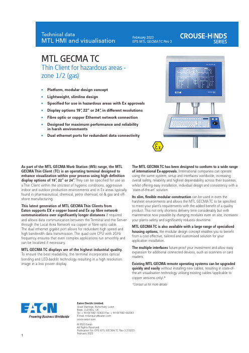
1Eaton Electric Limited,Great Marlings, Butterfield, Luton Beds, LU2 8DL, UK.Tel: + 44 (0)1582 723633 Fax: + 44 (0)1582 422283E-mail:********************© 2023 EatonAll Rights ReservedPublication No. EPS MTL GECMA TC Rev 3 210223February 2023As part of the MTL GECMA Work Station (WS) range, the MTL GECMA Thin Client (TC) is an operating terminal designed to enhance visualization within your process using high definition display options of 19”, 22” or 24”. They can be specified for use as a Thin Client within the strictest of hygienic conditions, aggressive indoor and outdoor production environments and in Ex areas typically found in pharmaceutical, chemical, petro chemical, oil & gas and off-shore manufacturing.This latest generation of MTL GECMA Thin Clients from Eaton supports EX e copper based and Ex op fibre network communications over significantly longer distances if required and allows data communication between the Terminal and the Server through the Local Area Network via copper or fibre optic cable. The dual ethernet gigabit port allows for redundant high speed and high bandwidth data transmission. The quad core CPU with 2GHz frequency ensures that even complex applications run smoothly and can be localized if necessary.MTL GECMA TC displays are of the highest industrial quality. To ensure the best readability, the terminal incorporates optical bonding and LED-backlit technology resulting in a high resolution image in a low power display.MTL GECMA TCThin Client for hazardous areas -zone 1/2 (gas)The MTL GECMA TC has been designed to conform to a wide range of international Ex-approvals. International companies can operate using the same system, setup and interfaces worldwide, increasing overall safety, reliability and highest dependability across their business, whilst offering easy installation, individual design and consistency with a ‘state-of-the-art’ solution.Its slim, flexible modular construction can be used in even theharshest environments and allows the MTL GECMA TC to be specified to meet your plant’s requirements with the added benefit of a quality product. This not only shortens delivery time considerably but withmaintenance now possible by changing modules even on site, increases your plants safety and significantly reduces downtime.MTL GECMA TC is also available with a large range of specialised housing options, the modular design concept enables you to benefit from a cost effective, tailored and customised solution for your application installation.The multiple interfaces future-proof your investment and allow easy expansion for additional connected devices, such as scanners or card readers.Existing MTL GECMA remote operating systems can be upgraded quickly and easily without installing new cables, resulting in state-of-the-art visualisation technology utilising existing cables (applicable tocopper versions only).**Contact us for more details• Platform, modular design concept • Lightweight, slimline design• Specified for use in hazardous areas with Ex approvals • Display options 19”, 22” or 24”, in different resolutions • Fibre optic or copper Ethernet network connection • Designed for maximum performance and reliability in harsh environments• Dual ethernet ports for redundant data connectivitySPECIFICATIONELECTRICALMECHANICALENVIRONMENTALCERTIFICATIONFor the latest certification information visit /certificates 2The given data is only intended as a productdescription and should not be regarded as a legal warranty of properties or guarantee. In the interest of further technical developments, we reserve the right to make design changes.Eaton Electric Limited,Great Marlings, Butterfield, Luton Beds, LU2 8DL, UK.Tel: + 44 (0)1582 723633 Fax: + 44 (0)1582 422283E-mail:********************© 2023 EatonAll Rights ReservedPublication No. EPS MTL GECMA TC Rev 3 210222February 2023EUROPE (EMEA): +44 (0)1582 723633 ********************THE AMERICAS: +1 800 835 7075*********************ASIA-PACIFIC:+65 6645 9864 / 9865***********************318-36 100-230 8-36 V DC //00-230 V ACThin ClientOPERATING PRINCIPLEMODULE OVERVIEWFurther enclosure options on request*Please contact your local sales office for these optionsENCLOSURE OPTIONSWall mounting*Floor mounting (standard)Ceilingmounting*。


RoHSHow to OrderdesignationNote 1) Fluid varies depending on the applicable fittings.Note 2) When using a liquid fluid, the surge pressure must not exceed the maximum operating pressure. If the surge pressureexceeds the maximum operating pressure, it will result in damage to fittings and tubes. Furthermore, abnormaltemperature rise caused by adiabatic compression may result in the tube bursting.Note 3) Do not use this product in a manner in which the tube is not fixed. Observe the lesser value of the maximum operatingpressure between the tube and fitting. A material change over a long duration or due to high-temperature may causeleakage. Perform periodic maintenance and replace with a new product immediately when abnormalities are detected.(Refer to “Maintenance” in the Series TLM/TILM Specific Product Precautions.) Refer to “Handling Precautions for SMCProducts” (M-E03-3) for Fittings and Tubing Precautions and “Fluoropolymer Piping Equipment” (CAT.ES70-39) forFluoropolymer Fittings Precautions.Note 4) Minimum bending radius is measured as shown left as representative values.• Use a tube above the recommended minimum bending radius.• The tube may be bent if used under the recommended minimum bending radius. Therefore, refer to the refraction valueand make sure that the tube is not bent or flattened.• Please note that the refraction value is not warranted because of the value when 2R is measured by the method in theright figure if the tube is bent or flattened, etc.SpecificationsFluid: Air, Water, Inert gas Fittings: One-touch fittings KQ2, KJ, KQG2, Insert fittings KFG2Fluid: Refer to “Applicable F I uid List.”Fittings: Fluoropolymer fittings LQ1, LQ2, LQ3260 CPFA (Tetrafluoroethylene perfluoroalkoxy vinyl ether copolymer)Refer to the max. operating pressure curve.20121062520352060309560220160400290500360 Max. operating temperatureMaterialRecommended radiusRefraction valueMin. bendingradius (mm) Note 4)Max. operating pressure (MPa)How to measure theminimum bending radiusFixedendAt a temperature of 20 C, bend thetubing into a U shape. Fix one endand gradually move the other endcloser. Measure 2R at the pointwhere the outside diameter’s rate ofchange is 5%.Fluid Note 1) 2) 3) andapplicable fittings Note 1) 2) 3)the tubing length differs dependingon each size.Max. Operating PressureFluoropolymer Tubing (PFA)Inch SizeSeries TILMCourtesyofCMA/Flodyne/Hydradyne▪MotionControl▪Hydraulic▪Pneumatic▪Electrical▪Mechanical▪(8)426-548▪www.cmafh.comNote) “Chemically inert” means – not to cause any chemical reaction.Chemicals in the list below are chemically inert Note), to PFA material. Possible physical effects may occur such as penetration and swelling due to temperature, pressure and chemical concentration.To use PFA tube in a chemical environment, tests should be performed with the same environment to ensure no problem occurs with operating environment.Series TLM/TILMApplicable Fluid ListChemical resistance of Fluoropolymer PFA materialAcetateAcetic anhydride Acetone Acetylene Acrylonitrile Aluminum acetate Aluminum nitrate Aluminum bromide Aluminum chloride Aluminum fluoride Aluminum sulfate Ammonia gas Ammonium carbonate Ammonium chloride Ammonium hydroxide Ammonium nitrate Ammonium nitrite Ammonium persulfate Ammonium phosphate Ammonium sulfate Amyl acetate Amyl alcohol Amyl borate Amyl naphthalene Aniline Aniline dye Animal oil (Lard oil)Aqua regia Arsenic acid Asphalt Barium chloride Barium hydroxide Barium sulfate Barium sulfide BeerBeet sugar liquors Benzaldehyde BenzineBenzene (Benzol)Benzyl alcohol Benzyl benzoate Benzyl chloride Borax Boric acid Bromine Bunker oil Butane Butter Butyl acetate Butyl acrylateButyl alcohol (Butanol)Butyl stearate Calcium acetate Calcium bisulfite Calcium chloride Calcium hydroxide Calcium hypochlorite Calcium nitrate Calcium sulfide Carbon dioxide Carbon disulfide Carbonic acid Castor oilCaustic soda (30%)Cellosolve Chlorosulfonic acid Chlorotoluene Chromic acid Citric acid Coconut oil Copper cyanide Copper sulfate Corn oil Cottonseed oil Creosote oil Cresol Cupric chloride Cyclohexane CyclohexanolCyclohexanone (Anon)Dibutyl phthalate Dichlorobenzene Diethyl sebacate Diethylene glycol Diisopropyl keton Dioctyl phthalate Dioctyl sebacate Dipentene (Limonene) Diphenyl Diphenyl oxide Epichlorohydrin Ethanolamine Ethyl acetate Ethyl acetoacetate Ethyl acrylate Ethyl alcohol Ethyl benzene Ethyl cellulose Ethyl chloride Ethyl oxalate Ethyl silicateEthylene chlorohydrinEthylene dicloride Ethylene glycol Ethylene oxide Ethylenediamine Fatty acid Ferric chloride Ferric nitrate Ferric sulfate Fluorboric acid Fluorobenzene Fluosilicic acid Formaldehyde Formic acid Furfural Gasoline Gelatine Glauber's salt Glucose Glue Glycerine Grease Hexaldehyde Hexane Hexyl alcohol Hydrobromic acid Hydrochloric acid Hydrocyanic acid Hydrofluoric acid (49%)Hydrofluoric acid anhydrous Hydrogen peroxide (30%)Hydrogen sulfide Hydroquinone Hypochlorous acid Isobutyl alcohol Isooctane Isopropyl acetate Isopropyl alcohol Isopropyl ether Kerosene Lead acetate Lead nitrate Lead sulfamate Linolenic acid Linseed oil Liquid ammoniaLPG (Liquefied petroleum gas)Lubricating oil Magnesium chloride Magnesium hydroxide Magnesium sulfate Maleic acidMalic acid Mercaptan Mercuric chloride Mercury Methyl acetate Methyl alcohol Methyl chloride Methyl ethyl ketone Methyl isobutyl ketone Methyl methacrylate Methylene dichloride Mineral oilMonochloroacetic acid Monochlorobenzene Monoethanolamine Naphtha Naphthalene Naphthenic acid Natrium peroxide Natural gas Nickel acetate Nickel chloride Nickel sulfate Nitric acid (60%)Nitrobenzene Nitroethane Nitromethane Nitropropane Octyl alcohol Oxalic acid Oxygen Ozone Palmitic acid Perchlorate Perchloroethylene Petroleum PhenolPhosphoric acid (75%)Picric acid PiperidinePotassium chloride Potassium dichromate Potassium hydroxide Potassium nitrate Potassium permanganate Potassium sulfate Propyl acetate Propyl alcohol Propylene Pyridine PyrroleSalicylic acid Silicate ester Silicone grease Silicone oil Silver nitrate Sodium bicarbonate Sodium bisulfate Sodium bisulfiteSodium hypochlorite (5%)Sodium metaphosphate Sodium nitrate Sodium perborate Sodium phosphate Sodium sulfite Sodium thiosulfate Soybean oil Stannic chloride Stearic acid Styrene Sucrose solution Sulfur Sulfur chloride Sulfuric acid (98%)Sulfurous acid gas Tannic acid Tartaric acid Terpineol Tetrachloroethane Tetraethyl lead Tetrahydrofuran Tetralin Thionyl chloride TriacetinTributoxy ethyl phosphate Tributyl phosphate Trichloroethylene Tricresyl phosphate Triethanolamine Tung oil Turpentine oil Vegetable oil Vinegar Water Whiskey Xylene Zeolite Zinc acetate Zinc chloride Zinc sulfide3C o u r t e s y o f C M A /F l o d y n e /H y d r a d y n e ▪ M o t i o n C o n t r o l ▪ H y d r a u l i c ▪ P n e u m a t i c ▪ E l e c t r i c a l ▪ M e c h a n i c a l ▪ (800) 426-5480 ▪ w w w .c m a f h .c o mSelection Air SupplyWarningWarning1.Check the specifications.Products represented in this catalog are designed only for use in compressed air systems (including vacuum).Do not operate at pressures or temperatures, etc., beyond the range of specifications, as this can cause damage or malfunction. (Refer to the specifications.)2.When using the product for medical careThis product is designed for use with compressed air system applications for medical care purposes. Do not use in contact with human bodily fluids, body tissues or transfer applications to a human living body.Caution1.Do not use in locations where the connecting threads and tubing connection will slide or rotate.The connecting threads and tubing connection will come apart under these conditions.e tubing at or above the minimum bending radius. Using below the minimum bending radius can cause breakage or flattening of the tubing.3. Never use the tubing for anything flammable, explosive or toxic such as gas, fuel gas, or cooling mediums, etc.Because the contents may penetrate outward.e the fittings applicable to the tubing size.MountingCaution1.Check the model number, size, etc. before installing.The TLM and TILM series do not have the model number displayed on the product due to the resin material used. If tubing without a model label is mixed with other tubing which also does not have a model label, it is impossible to identify the model. Please avoid mixing the products with other models while it is being used and/or stored. Also, check tubing for damage, gouges, cracks, etc.2. When tubing is connected, consider factors such as changes in the tubing length due to pressure, and allow sufficient leeway.3. Do not apply unnecessary forces such as twisting, pulling, moment loads, etc. on fittings or tubing.This will cause damage to fittings and will crush, burst or release tubing.4.Mount so that tubing is not damaged due to tangling and abrasion.This can cause flattening, bursting or disconnection of tubing, etc.PipingCaution1.Preparation before pipingBefore piping is connected, it should be thoroughly blown out with air (flushing) or washed to remove chips, cutting oil and other debris from inside the pipe. Not allowing chips of the piping thread or the seal material to go in.1.In case of excessive condensationExcessive condensation in a compressed air system may cause pneumatic equipment to malfunction. Installation of an air dryer, water droplet separator before filter is recommended.2.Drain flushingIf condensation in the drain bowl is not emptied on a regular basis, the bowl will overflow and allow the condensation to enter the compressed air lines.It causes a malfunction of pneumatic devices.If the drain bowl is difficult to check and remove, installation of a drain bowl with an auto drain option is recommended. For compressed air quality, refer to SMC’s “Air Preperation Equipment Model Selection Guide.”MaintenanceCaution1. Perform periodic inspections to check the following problems and replace tubing, if necessary.a) Cracks, gouges, wearing, corrosion b) Air leakagec) Twists or crushing of tubingd) Hardening, deterioration, softening of tubing2.Do not repair or patch the replaced tubing or fittings for reuse.3. When using insert or miniature fittings over a long period, some leakage may occur due to age deterioration of the materials. If any leakage is detected, correct the problem by additional tightening.If tightening becomes ineffective, replace the fittings with a new product immediately.Operating EnvironmentWarning1.Do not use in locations having an explosive atmosphere.2.Do not operate in locations where vibration or impact occurs.3.In locations near heat sources, block off radiant heat.Series TLM/TILMSpecific Product PrecautionsBe sure to read before handling. Refer to back cover for Safety Instructions, “Handling Precautions for SMC Products” (M-E03-3) for Fittings and Tubing Precautions and “Fluoropolymer Piping Equipment” (CAT.ES70-39) for Fluoropolymer Fittings Precautions.4C o u r t e s y o f C M A /F l o d y n e /H y d r a d y n e ▪ M o t i o n C o n t r o l ▪ H y d r a u l i c ▪ P n e u m a t i c ▪ E l e c t r i c a l ▪ M e c h a n i c a l ▪ (800) 426-5480 ▪ w w w .c m a f h .c o mand any obligation on the part of the manufacturer.Limited warranty and Disclaimer/Compliance RequirementsThe product used is subject to the following “Limited warranty and Disclaimer” and “Compliance Requirements”.Read and accept them before using the product.Limited warranty and Disclaimer1. The warranty period of the product is 1 year in service or 1.5 years after the product is delivered.∗2)Also, the product may have specified durability, running distance or replacement parts. Please consult your nearest sales branch.2. For any failure or damage reported within the warranty period which is clearly our responsibility, a replacement product or necessary parts will be provided.This limited warranty applies only to our product independently, and not to any other damage incurred due to the failure of the product.3. Prior to using SMC products, please read and understand the warranty terms and disclaimers noted in the specified catalog for the particular products.∗2) Vacuum pads are excluded from this 1 year warranty.A vacuum pad is a consumable part, so it is warranted for a year after it is delivered.Also, even within the warranty period, the wear of a product due to the use of the vacuum pad or failure due to the deterioration of rubber material are not covered by the limited warranty.Compliance Requirements1. The use of SMC products with production equipment for the manufacture of weapons of mass destruction (WMD) or any other weapon is strictly prohibited.2. The exports of SMC products or technology from one country to another are governed by the relevant security laws and regulations of the countries involved in the transaction. Prior to the shipment of a SMC product to another country, assure that all local rules governing that export are known and followed.These safety instructions are intended to prevent hazardous situations and/or equipment damage. These instructions indicate the level of potential hazard with the labels of “Caution,” “Warning” or “Danger .” They are all important notes for safety and must be followed in addition to International Standards (ISO/IEC)∗1), and other safety regulations.∗1)ISO 4414: Pneumatic fluid power – General rules relating to systems.ISO 4413: Hydraulic fluid power – General rules relating to systems.IEC 60204-1: Safety of machinery – Electrical equipment of machines.(Part 1: General requirements)ISO 10218-1: Manipulating industrial robots - Safety.etc.C o u r t e s y o f C M A /F l o d y n e /H y d r a d y n e ▪ M o t i o n C o n t r o l ▪ H y d r a u l i c ▪ P n e u m a t i c ▪ E l e c t r i c a l ▪ M e c h a n i c a l ▪ (800) 426-5480 ▪ w w w .c m a f h .c o m。

Doc No.: 003006-120117Revision Date: 2017-12-01 SECTION 1. - - - - - - - - - - - - - PRODUCT IDENTIFICATION - - - - - - - - - - - - - - - - - - - - - - - -TheraTest Laboratories, Inc.1120 N. DuPage Ave.Lombard, IL 60148General information telephone number: 800-441-0771Emergency telephone number: 800-441-0771Product Name & Catalog No.: EL-ANA Profiles Anti-dsDNA Kit (Cat. No. 104-201)Intended Use: EL-ANA Profiles Anti-dsDNA Kit (Cat. No. 104-201) is an in vitro diagnostic test for the detection and measurement of autoantibodies directed against the following autoantigens: double-stranded DNA (dsDNA). This test system is intended as an aid in diagnosis of systemic lupus erythematosus,Sjögren’s syndrome, progressive systemic sclerosis (scleroderma), drug-induced lupus and polymyositis. SECTION 2. - - - - - - - - - - - - - HAZARDS IDENTIFICATION - - - - - - - - - - - - - - - - - - - - - - - -Emergency OverviewOSHA HazardsNo known OSHA hazardsOther hazards which do not result in classificationNot a dangerous substance or mixture according to the Globally Harmonized System (GHS).GHS ClassificationN/AGHS Label elements, including precautionary statementsPictogram: NoneSignal word: NoneHazard StatementsNonePrecautionary statementsNonePotential Health EffectsInhalation: May be harmful if inhaled. May cause respiratory tract irritation.Skin: May be harmful if absorbed through the skin. May cause skin irritation. Eyes: May cause eye irritation. Ingestion: May be harmful if swallowed.Target Organs: None identified.Human Source Material: Treat as potentially infectious.Serum used in the preparation of this product has been tested by FDA approved methods and found non- reactive for the presence of Hepatitis B surface antigen (HBsAg), antibody to human immunodeficiency virus (HIV) and Hepatitis C virus (HCV). No known test method can offer complete assurance that Hepatitis B virus, HIV, HCV, or other infectious agents are absent. Handle these controls and all patient samples at Biosafety Level 2 as recommended in the Biosafety in Microbiological and Biomedical Laboratories, Centers for Disease Control and Prevention/National Institutes of Health, Fifth Edition, 2007.NOTE: Physical and health hazard information for this component has not been determined. Any physical and health information noted is based on evaluation of data for pure ingredients and concentration of ingredients as packaged.NFPA: HEALTH = 0, FIRE = 0, REACTIVITY = 0HMIS: HEALTH = 0, FLAMMABILITY = 0, PHYSICAL HAZARDS = 0SECTION 3. - - - - - - - COMPOSITION/INFORMATION ON INGREDIENTS - - - - - - - - - - - - -No ingredients are hazardous according to OSHA criteriaKit componentsNOTE: PN = Part NumberPN 3900, 3800 Polystyrene microwells ELISA plates coated with antigenPN 3803, ANA dsDNA ELISA Negative Control, vial containing 0.35ml of human serum, buffer and preservatives≤0.02% Sodium Azide, and ≤0.1% of 2-Methyl-4-isothiazolin-3-onePN 3824, ANA dsDNA ELISA Positive Control, vial containing 0.35ml of human serum, buffer and preservatives≤0.02% Sodium Azide, and ≤0.1% of 2-Methyl-4-isothiazolin-3-onePN 3905, ANA ELISA dsDNA calibrator 2 vials, containing 1.5ml of buffer, protein, diluted human serum, buffer and preservatives ≤0.02% Sodium Azide, and ≤0.1% of 2-Methyl-4-isothiazolin-3-onePN 3750, ANA Specimen Diluent: 1 bottle containing 100ml of phosphate buffered saline, protein, ≤0.05% Polysorbate 20 and preservative ≤0.1% of 2-Methyl-4-isothiazolin-3-onePN 3754, 10X Wash Concentrate: 1 bottle of concentrate containing 100 ml phosphate buffered saline, ≤0.5% Polysorbate 20 and preservative ≤0.1% of 2-Methyl-4-isothiazolin-3-onePN 24322, ANA IgG Enzyme conjugate: goat anti-human IgG, conjugated w/horseradish peroxidase, 1 bottle containing 27ml of buffer, protein, and ≤0.1% of 2-Methyl-4-isothiazolin-3-onePN 15879, Chromogen: 1 bottle containing 27ml of TMB (3,3’,5,5’-tetramethylbenzidine) (>99%),PN 24321, Stop Reagent, 1 bottle containing 27ml of ≤2M Phosphoric AcidSECTION 4. - - - - - - - - - - - - - - - FIRST-AID MEASURES - - - - - - - - - - - - - - - - - - - - - - - - - -Eye: Rinse immediately with plenty of clean running water for at least 20 minutes, separating the eyelid. Skin Contact: Wash off thoroughly with plenty of clean running water. Remove and wash contaminated clothing. Ingestion: Obtain immediate medical attention.Inhalation: Remove from exposure. If breathing is difficult, obtain medical attention if necessary.IN CASE OF ACCIDENT OR IF YOU DO NOT FEEL WELL, IMMEDIATELY SEEK MEDICAL ADVICE. SECTION 5. - - - - - - - - - - - - - FIRE FIGHTING MEASURES - - - - - - - - - - - - - - - - - - - - - - - -Non-flammable preparation.Extinguishing media: Use media in adaption to materials stored in the immediate neighborhood, such as dry chemical.Special firefighting procedures: Wear self-contained breathing apparatus and protective clothing to prevent contact with skin and eyes.SECTION 6. - - - - - - - - - - ACCIDENTAL RELEASE MEASURES - - - - - - - - - - - - - - - - - - - - -After spillage: Wipe up spills with inert absorbent materials and place in a suitable container. Use personal protective equipment (PPE), such as gloves, safety glasses/goggles to prevent exposure.SECTION 7. - - - - - - - - - - - - - - - HANDLING AND STORAGE - - - - - - - - - - - - - - - - - - - - - - -Handling: Normal precautions for handling chemicals must be observed. Wash affected area after handling. Storage: Keep containers tightly closed when not in use. Store in a dry, well ventilated storage area (2-8°C).Protect from physical damage.SECTION 8. - - - - - - - EXPOSURE CONTROLS/PERSONAL PROTECTION - - - - - - - - - - - - -Contains no substances with occupational exposure limit values.Respiratory protection: Where risk assessment shows air purifying respirators are appropriate use a full face respirator with multi-purpose combination (US) or type ABEK (EN 14387) respirator cartridges as a back up to engineering controls. If the respirator is the sole means of protection, use a full-face supplied air respirator. Use respirators and components tested and approved under appropriate government standards such as NIOSH (US) or CEN (EU).Eye protection: Use equipment for eye protection tested and approved under appropriate government standards such as NIOSH (US or EN 166 (EU).Hand protection: Handle with gloves. Gloves must be inspected prior to use. Use proper glove removal technique (without touching glove’s outer surface) to avoid skin contact with this product. Dispose of contaminated gloves after use in accordance with applicable laws and good laboratory practices. Wash and dry hands.Skin and body protection: Impervious clothing. The type of protective equipment must be selected according to the concentration and amount of the dangerous substance at the specific workplace. Hygiene measures: Handle in accordance with good industrial hygiene and safety practice. Wash hands before breaks and at the end of the workday.Recommend the use of safety pipette device.SECTION 9. - - - - - - - - - PHYSICAL AND CHEMICAL PROPERTIES - - - - - - - - - - - - - - - - - -Appearance:Microtiter plate: solid polystyrene plasticConjugate: (IgG) green, LiquidsANA specimen Diluent: yellow liquidPositive Control: pale yellow liquidNegative Control: pale yellow liquidCalibrator: pale yellow liquidWash Concentrate: clear colorless liquidTMB: pale yellow liquid (possibly exhibiting a slight blue tinge)Stop Solution: clear colorless liquidOdor: Solutions are odorlessBoiling point: N/AMelting point: N/AFlash point: N/AIgnition temperature: N/AExplosion limits: N/AVapor pressure: N/ADensity: N/AViscosity: N/ASolubility in water: Solutions are solubleSECTION 10. - - - - - - - - - - - - STABILITY AND REACTIVITY - - - - - - - - - - - - - - - - - - - - - - -Stability: Stable under ordinary conditions of use and storage.Hazardous Polymerization: Will not occur.Conditions and materials to avoid: N/AHazardous reactions: N/AHazardous decomposition products: N/ASECTION 11. - - - - - - - - - - TOXICOLOGICAL INFORMATION - - - - - - - - - - - - - - - - - - - - - -Acute toxicityOral LD50No data available Inhalation LC50 No data available Dermal LD50 No data availableOther information on acute toxicityNo data availableSkin corrosion/irritation No data available Serious eye damage/eye irritationNo data availableRespiratory or skin sensitization No data availableGerm cell mutagenicity No data available CarcinogenicityIARCNo component of this product present at levels greater than or equal to 0.1% is identified as probable, possible or confirmed human carcinogen by IARC.NTPNo component of this product present at levels greater than or equal to 0.1% is identified as known or anticipated carcinogen by NTP.OSHANo component of this product present at levels greater than or equal to 0.1% is identified as carcinogen or potential carcinogen by OSHA.Reproductive toxicity No data available Teratogenicity No data availableSpecific target organ toxicity – single exposure (Globally Harmonized System)No data availableSpecific target organ toxicity – repeated exposure (Globally Harmonized System) No data available Aspiration hazard No data availablePotential health effects InhalationMay be harmful if inhaled. Causes respiratory tract irritation.IngestionHarmful if swallowed.SkinHarmful if absorbed by the skin. Causes skin irritationEyesCauses eye irritationSigns and Symptoms of ExposureProlonged or repeated exposure can cause: central nervous system depression, nausea, headache, vomiting.To the best of our knowledge, the chemical, physical, and toxicological properties have not been fully investigated.Synergistic effectsNo data available Additional InformationRTECS: Not availableSECTION 12. - - - - - - - - - - - - - ECOLOGICAL INFORMATION - - - - - - - - - - - - - - - - - - - - - -ToxicityNo data available. Persistence and degradabilityNo data available. Bioaccumulative potential No data available. Mobility in soilNo data available.PBT and vPvB Assessment No data available.Other adverse effectsAn environmental hazard cannot be excluded in the event of unprofessional handling or disposal. Toxic to aquatic life.SECTION 13. - - - - - - - - - - - - DISPOSAL CONSIDERATIONS - - - - - - - - - - - - - - - - - - - - - - -Observe all Governmental environmental regulations for waste disposal. Chemical waste generators must determine if a discarded chemical is classified as a hazardous waste. Contact a licensed professional waste disposal service for disposal of unused product.Some reagents in this kit contain Sodium Azide as a preservative. Sodium Azide has been reported to form lead or Copper Azide in laboratory plumbing which may explode on percussion. Use proper disposal procedures.ProductOffer surplus and non-recyclable solutions to a licensed company. Contaminated packagingDisposed of as an unused product.Remains of biological samples, reagents and controls should be collected in a suitable container for this purpose and autoclaved 1 hour at 121ºC.SECTION 14. - - - - - - - - - - - - - TRANSPORT INFORMATION - - - - - - - - - - - - - - - - - - - - - - -DOT (US)Not dangerous goods. IMDGNot dangerous goods IATANot dangerous goods.SECTION 15. - - - - - - - - - - - - - REGULATORY INFORMATION - - - - - - - - - - - - - - - - - - - - - -According to 1999/45/EC Directive and 91/155/EEC Directive and following modifications.OSHA Hazards:Target Organ Effect: Harmful by ingestion. IrritantTSCA Status:Not on TSCA Inventory.Antibody, liquid CAS# None, EINECS# NoneDSL StatusThis product contains the following components that are not on the Canadian DSL nor NDSL lists. Antibody, liquid CAS# None, EINECS# NoneSARA 302 Components:The following components are subject to the reporting requirements of SARA Title III, Section 302. Sodium azide, CAS# 26628-22-8, EINECS# 247-852-1Phosphoric acid, CAS# 7664-38-2, EINECS# 231-633-2SARA 313 Components:The following components are subject to the reporting requirements of SARA Title III, Section 313. Phosphoric acid, CAS# 7664-38-2, EINECS# 231-633-2SARA 311/312 Hazards:Acute Health Hazard, Chronic Health HazardMassachusetts Right To Know Components: Sodium azide, CAS# 26628-22-8, EINECS# 247-852-1 Chloramphenicol, CAS# 56-75-7, EINECS# 200-287-4Phosphoric acid, CAS# 7664-38-2, EINECS# 231-633-2Pennsylvania Right To Know Components:3,3’,5,5’-tetramethylbenzidine, CAS# 54827-17-7, EINECS# 259-364-6Water, CAS# 7732-18-5, EINECS# 231-791-2Sodium azide, CAS# 26628-22-8, EINECS# 247-852-1Tween 20, CAS# 9005-64-5, EINECS# NoneChloramphenicol, CAS# 56-75-7, EINECS# 200-287-4Phosphoric acid, CAS# 7664-38-2, EINECS# 231-633-2New Jersey Right To Know Components:3,3’,5,5’-tetramethylbenzidine, CAS# 54827-17-7, EINECS# 259-364-6Water, CAS# 7732-18-5, EINECS# 231-791-2Tween 20, CAS# 9005-64-5, EINECS# NoneChloramphenicol, CAS# 56-75-7, EINECS# 200-287-4Phosphoric acid, CAS# 7664-38-2, EINECS# 231-633-2California Prop. 65 Components:This product does not contain any chemicals known to State of California to cause cancer, birth, or any other reproductive defects.SECTION 16. - - - - - - - - - - - - - - - OTHER INFORMATION - - - - - - - - - - - - - - - - - - - - - - - - -Each donor unit used in the preparation of the controls of this kit was tested by an approved method for the presence of the antibodies to HIV and HCV as well as for HBsAg and found to be negative.WARNING: Because no test method can offer complete assurance that HIV, HCV, HBsAg or other infectious agents are absent, the controls of this kit should be handled carefully using Universal Precautions.TheraTest Laboratories, Inc. provides the information contained herein in good faith but makes no representation as to its comprehensiveness or accuracy. This document is intended only as a guide to the appropriate precautionary handling of the material by properly trained personnel using this product.Individuals receiving the information must exercise their independent judgment in determining its appropriateness for a particular purpose. TheraTest Laboratories, Inc. makes no representations or warranties, either expressed or implied, including without limitation any warranties of merchantability, fitness for a particular purpose with the respect to the information set forth herein or the product to which the information refers. Accordingly, TheraTest Laboratories, Inc. will not be liable for any claims, losses or damages resulting from use of or reliance upon this information.。

AC/DC Co nverterRAC05-K/PD3/H5 Watt2‘‘ x 1‘‘Single OutputREACHcompliantRoHS 2+compliant10 from 10IEC/EN62368-1 compliant UL61010-1 certified (4)CSA C22.2 No. 61010-1 certified (4)IEC/EN61010-1 certified IEC/EN61204-3 compliant EN55032 compliant EN55014-1 compliant EN55014-2 compliant EN55024 compliant EN61000 compliant CB ReportSelection GuidePart Input Output Output Efficiency Max. CapacitiveNumber Voltage Range Voltage Current typ (1)(2)[VAC] [VDC] [mA] [%] [µF]RAC05-05SK/PD3/H 90-3185 1000 73 10000 RAC05-12SK/PD3/H 90-318 12 420 74 1200On RequestRAC05-15SK/PD3/H 90-31815330741000Notes:Note1: Efficiency is tested at 277VAC and full load at +25°C ambient Note2: Max Cap Load is tested at nominal input and full resistive loadModel NumberingOrdering Examples:RAC05-05SK/PD3/H 5Vout Single Output RAC05-12SK/PD3/H 12VoutSingle OutputS inglenom. Output PowerOutput VoltageRAC05-__ _K/PD3/H5003727BASIC CHARACTERISTICSParameterConditionMin.Typ.Max.Nominal Input Voltage 50/60Hz 100VAC 277VAC Operating Range (3)47-63Hz 90VAC277VAC318VAC Absolute Maximum Input Voltage (4)528VAC Input Current 100VAC 277VAC 110mA 60mAInrush Currentcold start at +25°C20ANo load Power Consumption 500mWMinimum Load0%Specifications (measured @ Ta= 25°C, 277VAC, full load and after warm-up unless otherwise stated)E470721DescriptionThe RAC05-K/PD3/H series of 5 watt AC/DC are IE C61010 safety rated to PD3 and OVCIII by UL for 100-277VAC nominal input lines (-10/+15%). The modules support an operating temperature range from -40°C to +85°C in harsh environments with a possible excessive increase in the input conditions up to 400Vac / 480Vac, permanently without damage. Fully protected outputs as well as EMC class A and B compliance without external components for floating installations. All these features make them an ideal fit for integration into smart grid, renewable energy, smart metering and IoT applications.3Notes:Note3: Refer to …Line Derating“Note4: UL61010-1 valid for Input Range 90-318VAC onlySpecifications (measured @ Ta= 25°C, 277VAC, full load and after warm-up unless otherwise stated)Specifications (measured @ Ta= 25°C, 277VAC, full load and after warm-up unless otherwise stated)PROTECTIONSParameter Type Value Input Fuse (6)external slow blow 350VAC, 2A Limited Power Source (LPS)according to IEC62368-1 CB Report Short Circuit Protection (SCP)below 100m W hiccup, automatic restart Over Voltage Protection (OVP)150% - 195%, hiccup mode Over Voltage Category OVC III Over Current Protection (OCP)150% - 195%, hiccup mode Class of Equipment Class IIENVIRONMENTALParameter Condition ValueOperating Temperature Range@ natural convection 0.1m/s 5Voutfull load-40°C to +70°C refer to …Derating Graph“-40°C to +80°C 12Voutfull load-40°C to +80°C refer to …Derating Graph“-40°C to +85°CMaximum Case Temperature+100°C Temperature Coefficient0.05%/K Thermal Impedance 0.1m/s16K/W Operating Altitude5000m Pollution Degree PD3 Operating Humidity non-condensing5% - 95% RH max.Vibration according to MIL-STD-202G 10-500Hz, 2G 10min./1cycle, period 60min. each along x,y,z axesDesign Lifetime +25°C+60°C105 x 103 hours40 x 103 hoursMTBF according to MIL-HDBK-217F, G.B.+25°C+40°C>1726 x 103 hours>1585 x 103 hoursSpecifications (measured @ Ta= 25°C, 277VAC, full load and after warm-up unless otherwise stated)SAFETY AND CERTIFICATIONSCertificate Type (Safety)Report Number StandardAudio/video, information and communication technology equipment - Safety requirements (LVD)200811140GZU-001IEC62368-1:2014, 2nd EditionEN62368-1:2014 + A11:2017Safety requirements for electrical equipment for measurement, control and laboratory use - Part 1: General requirements E470721UL61010-1CAN/CSA C22.2 No. 61010-1Safety requirements for electrical equipment for measurement, control and laboratory use -Part 1: General requirements190415125GZU-001EN61010-1:2010Safety requirements for electrical equipment for measurement, control and laboratory use -Part 1: General requirements (CB Scheme)IEC61010-1:2010 + A1:2016 3rd Edition EAC RU-AT.03.67361TP TC 004/020, 2011 RoHS2RoHS-2011/65/EU + AM-2015/863 EMC Compliance Condition Standard / CriterionLow-voltage power supplies DC output - Part 3: Electromagnetic compatibilityLCS180508025BE IEC/EN61204-3:2018, Class BElectromagnetic compatibility of multimedia equipment – Emission Requirements (8)EN55032:2015, Class B Electromagnetic compatibility of household appliances, electric tools and similar apparatus- Emission RequirementsEN55014-1:2006+A2:2011 Information technology equipment - Immunity characteristics - Limits and methods ofmeasurementEN55024:2010+A1:2015 Electromagnetic compatibility of household appliances, electric tools and similar apparatus- Immunity RequirementsEN55014-2:2015ESD Electrostatic discharge immunity test Air: ±15, 8, 4, 2kVContact: ±8, 4, 2kVEN61000-4-2: 2009, Criteria ARadiated, radio-frequency, electromagnetic field immunity test 10V/m, 80MHz-1GHz3V/m, 1.5GHz-2GHz1V/m, 2GHz-2.7GHzEN61000-4-3: 2006 + A1:2009, Criteria AFast Transient and Burst ImmunityAC In Port: ±2.0kVDC Out Port: ±2.0kVEN61000-4-4:2012, Criteria ASurge Immunity AC IN Port: L-N ±4.0kVDC Out Port: ±0.5kVEN61000-4-5:2014+A1:2017, Criteria AImmunity to conducted disturbances, induced by radio-frequency fields10Vrms EN61000-4-6:2014, Criteria A Power Magnetic Field Immunity50Hz, 30A/m EN61000-4-8:2010, Criteria ASpecifications (measured @ Ta= 25°C, 277VAC, full load and after warm-up unless otherwise stated)EMC Compliance Condition Standard / CriterionVoltage Dips and InterruptionsDips 100%Dips 60, 30, 20%Interruptions > 95%EN61000-4-11:2004+A1:2017, Criteria BEN61000-4-11:2004+A1:2017, Criteria CEN61000-4-11:2004+A1:2017, Criteria CLimits of Voltage Fluctuations & Flicker EN61000-3-3:2013 Notes:Note8: If output is connected to GND, please contact RECOM tech support for advicePACKAGING INFORMATIONParameter Type Value Packaging Dimension (LxWxH)tube490.0 x 56.0 x 40.0mm Packaging Quantity15pcs Storage Temperature Range-40°C to +85°C Storage Humidity non-condensing20% to 90% RH max.The product information and specifications may be subject to changes even without prior written notice.The product has been designed for various applications; its suitability lies in the responsibility of each customer. The products are not authorized for use in safety-critical applications without RECOM’s explicit written consent. A safety-critical application is an application where a failure may reasonably be expected to endanger or cause。
Instruction LeafletAll possible contingencies which may arise during installation, operation or maintenance, and all details and variations of this equipment do not purport to be covered by these instructions. If further information is desired by purchaser regarding this particular installation, operation or maintenance of this equipment, the local ABB Inc. representative should be contacted.Printed in U.S.A .ABB!Before putting relays into service, remove all blocking which may have been inserted for the purpose of securing the parts during shipment,make sure that all moving parts operate freely,inspect the contacts to see that they are clean and close properly, and operate the relay to check the settings and electrical connections.1.0APPLICATIONThese relays have been specially designed and tested to establish their suitability for Class 1E applic-aitons. Materials have been selected and tested to insure that the relays will perform their intended func-tion for their design life when operated in a normal environment as defined by ANSI standard C37.90-1971, when exposed to radiation levels up to 104rads, and when subjected to seismic events produc-ing a Shock Response Spectrum within the limits of the relay rating.“Class 1E” is the safety classification of the electric equipment and systems in nuclear power generating stations that are essential to emergency shutdown of the reactor, containment isolation, cooling of the reactor, and heat removal from the containment and reactor, or otherwise are essential in preventing sig-nificant release of radioactive material to the environ-ment.The COQ is used to prevent a synchronous machinefrom being damaged due to negative sequence fault currents.2.0CONSTRUCTION & OPERATIONThe COQ consists of an induction disc overcurrent unit, a negative sequence filter, and an indicating contactor switch (ICS) (figures 1 and 2).2.1OVERCURRENT UNITThis is an induction-disc type unit operated by nega-tive sequence quantities supplied to an electromag-net in the rear of the relay. A voltage is induced in the secondary coil of this electromagnet by transformer action of the main coil. Both coils are located on the center leg of the electromagnet. Current flow is from the secondary coil to coils on the outer legs of the electromagnet. The reaction between the outer leg coil fluxes and the main coil flux creates an operating torque on a spiral shaped aluminum disc mounted on a vertical shaft.2.2INDICATING CONTACTOR SWITCH (ICS)The dc indicating contactor switch is a small clapper type device. A magnetic armature, to which leafspring mounted contacts are attached, is attracted to the magnetic core upon energization of the switch. When the switch closes, the moving contacts bridge two stationary contacts, completing the trip circuit. Also during this operation two fingers on the armature deflect a spring located on the front of the switch,which allows the operation indicator target to drop.The front spring, in addition to holding the target, pro-vides restraint for the armature and thus controls the41-161.21Effective:May 1981NEW INFORMATIONType COQ NegativeSequence Generator RelayFor Class 1E applications41-161.21COQ Negative Sequence Generator Relaypickup value of the switch.3.0CHARACTERISTICS3.1OVERCURRENT UNITThe COQ negative sequence relay is available with the following negative sequence current taps:3 3.25 3.5 3.8 4.2 4.6 5.0These tap values represent the current transformer secondary amperes which correspond to one per unit generator current. At these values of negative sequence current, the moving contact will leave the time dial stop and reach the stationary contacts in a time as determined by the time dial setting and as shown by figure 3. For example, with a time dial set-ting of “4” the relay will close its contacts in 30 sec-onds with the above tap currents applied to the relay. As shown by the curves of figure 4, the relay’s char-acteristic is defined by a generator characteristic of I22T = K. The relay characteristic is such that it coin-cides with the generator characteristic at 1 per unit negative sequence current but at higher values of negative sequence current, the relay characteristic is substantially parallel and slightly less than the gener-ator characteristic. In this manner, a suitable margin of safety is obtained between the two characteristics.Figure 4 defines the relay characteristics for two gen-erators – one with a permissible constant of “30” and the other with a constant of “90”. The time dial set-tings for these constants are “4” and “11” respec-tively. Similar protection for other generators with I22T constants between “30” and “90” is obtained by settings of the time dial. Figure 5 shows the neces-sary time dial settings for various I22T constants. By referring to this figure, the time dial can be set so that the relay protects different generators whose I22T constants range from “30” to “90”.Figure 6 demonstrates the use of a tap setting lower than the full load current of the machine to accommo-date I22T limits of 7 and 10 while still providing wide contact spacing. For this figure a tap setting of 3 is used with a machine full load current of 4.Typical time-current curves of the relay are shown in figure 3. Minimum pickup is approximately 0.6 of the tap value current. See table 1 for burdens and ther-mal ratings.Table 1:OVERCURRENT UNIT BURDEN AND THERMAL RATINGINPUT CONDITION PHASE CONTINUOUSRATINGAMPSONE SECONDRA TINGAMPSWA TTS A T4 AMPSVOLT AMPSA T 5 AMPSCIRCUIT IMPEDANCEZ∠θ(R+jX)THREE PHASE ABC5551001001008.31.32.98.33.84.70.33–0°0.15–110°0.19–52°0.33+j 0.000.05+j 0.140.11+j 0.15PHASE-TO-PHASE FAULT CONDITIONPHASE TO PHASE A-BB-CC-A5551001001006.13.410.26.58.011.50.26–-161.7°0.32–65°0.46–-152°-0.24+j 0.080.13+j 0.29-0.41+j 0.22 PHASE-TO-NEUTRAL FAULT CONDITIONPHASETO NEUTRAL A-NB-NC-N5551001001005.13.54.85.23.85.50.321–8.7°0.51–24.3°0.22–29.0°0.20+j 0.030.14+j 0.060.19+j 0.112COQ Negative Sequence Generator Relay41-161.213.2TRIP CIRCUITThe main contacts will safely close 30 amperes at 250 volts dc and the seal-in contacts of the indicating contactor switch will safely carry this current long enough to trip a circuit breaker.The indicating instantaneous trip contacts will safely close 30 amperes at 250 volts dc, and will carry this current long enough to trip a breaker3.3TRIP CIRCUIT CONSTANTSIndicating Contactor Switch Coil4.0SETTING CALCULATIONSDetermine from the machine manufacturer the per-missible I22T constant. From figure 5 find the required time dial setting.Depending upon which curve was used in establish-ing the time dial setting, determine the tap value.For I22T producing an intersection on the upper curve, use a tap setting equal to or less than machine full load. For example, a conventionally cooled tur-bine generator may have a limit of I22T = 30. Where I2 is negative sequence current expressed in terms of per unit stator current at rated KVA and T is in sec-onds. This produces an intersection on the upper curve of figure 5 showing a time dial setting of 4. If the machine full load current (based upon the cooling conditions at which I22T is stated) is 4.4 amperes, use a tap setting of 4.2 amperes.For I22T producing an inter section on the lower curve, use a tap setting equal to or lower than 3/4 of machine full load current. For example an inner-cooled turbine generator may have a limit of I22T = 10. This produces an intersection on the lower curve of figure 5 showing a time dial setting of 2.5. If the machine full load current (based upon the cooling conditions at which I22T is stated) is 4 amperes, use a tap setting of 3 amperes.This approach gives a conservative, protective char-acteristic.5.0SETTING THE RELAY5.1OVERCURRENT UNITInsert the tap screw in the appropriate tap deter-mined under “SETTING CALCULATIONS”.Adjust the time dial setting to the value determined under “SETTING CALCULATIONS”.5.2INDICATING CONTACTOR SWITCH (ICS) There are no settings to make on the indicating con-tactor switch (ICS).6.0INSTALLATIONThe relays should be mounted on switchboard pan-els or their equivalent in a location free from dirt, moisture, excessive vibration and heat. Mount the relay vertically by means of the four mounting holes on the flange for the semi-flush type FT case. The mounting screws may be utilized for grounding the relay. External toothed washers are provided for use in the locations shown on the outline and drilling plan to facilitate making a good electrical connection between the relay case, its mounting screws and the relay panel. Ground wires should be affixed to the mounting screws as required for poorly grounded or insulating panels. Other electrical connections may be made directly to the terminals by means of screws for steel panel mounting.For detail information on the FT case refer to I.L. 41-076 for semi-flush mounting.7.0ADJUSTMENTS & MAINTENANCE The proper adjustments to insure correct operation of this relay have been made at the factory. Upon receipt of the relay no customer adjustments, other than those covered under “SETTINGS” should be required.7.1PERFORMANCE CHECKThe following check is recommended to insure that the relay is in proper working order:1.Apply approximately 5 amperes, 3 phase posi-tive sequences current on 3 amp tap and seeAmpere PickupOhms dc Resistance0.28.51.00.372.00.10341-161.21COQ Negative Sequence Generator Relaythat relay does not operate.2.Set relay at #11 time dial and jumper terminals 2,6 and 8. Set tap 3 and apply 26.0 amperes intoterminal 3 and out of terminal 7. (See figure 7).Time of operation with relay in the case should be 3.2 seconds ±±8%.3.Repeat test with relay on 5.0 tap and 43.3amperes through terminals 7 and 9. Time of operation should be 3.2 seconds ±8%.7.2INDICATING CONTACTOR SWITCH (ICS) Close the main relay contacts and pass sufficient dc current through the trip circuit to close the contacts of the ICS. This value of current should not be greater than the particular ICS nameplate rating. The indica-tor target should drop freely.Repeat above except pass 85% of ICS nameplate rating current. Contacts should not pickup and target should not drop.7.3ROUTINE MAINTENANCEAll the relays should be inspected and the time of operation should be checked once a year or at such time intervals as may be dictated by experience to the suitable to the particular application. Phantom loads should not be used in testing induction-type relays because of the resulting distorted current wave form which produces a error in timing.All contacts should be cleaned periodically. A contact burnisher Style #182A836H01 is recommended for this purpose. The use of abrasive material for clean-ing contacts is not recommended, because of the danger of embedding small particles in the face of the soft silver and thus impairing the contact.7.4OVERCURRENT UNITApply a single phase current of 8.66 times tap value (5 per unit negative sequence current) using the test circuit of figure 7. Check that time of operation is in accordance with figure 3.8.0CALIBRATIONUse the following procedure for calibrating the relay if the relay has been taken apart for repairs or the adjustments disturbed. This procedure should not be used until it is apparent that the relay is not in proper working order. (See “PERFORMANCE CHECK”).8.1FILTERTo adjust the filter resistor tap for no response to positive-sequence current, remove the relay from case and proceed as follows:a.Jumper switch jaws 2 and 6b.Remove overcurrent unit, tap screwc.Pass 10 amperes into switch jaw 3 and outswitch jaw 7.d.With a 0-15 volt high input resistance type volt-meter (2000 ohm/volt or more), measure and record voltage between switch jaw 3 and the tap plate.e.Now measure the voltage across the resistor,between terminals 2 and 3. Adjust top filter resis-tor position until this voltage is 1.73 times the reading of (d) above.8.2OVERCURRENT UNITNOTE:A spring shield covers the reset spring of the overcurrent unit. To remove thespring shield, requires that the dampingmagnet be removed first. The screw con-nection holding the lead to the movingcontact should be removed next. The sec-ond screw holding the moving contactassembly should then be loosened notremoved. (Caution: this screw terminatesinto a nut held captive beneath themolded block. If screw is removed, diffi-culty will be experienced in the re-assem-bly of the moving contact assembly.)Slide the spring shield outward andremove from relay. Tighten the screwholding the moving contact assembly tothe molded block.Turn time dial until stationary contact is deflected against the back stop. Adjust, if necessary, so that “0” mark on time dial coincides with index. Then, with time dial at “0” wind up spring until about 5 1/2 con-volutions show. From this preliminary setting, and using 3 tap and time dial setting of “11”, adjust the permanent magnet until the relay operates in 8.2 seconds with 15.6 amperes single phase or 3 per unit between terminals 3 and 7 per figure 7. This adjustment is made by means of the damping mag-net screw.4COQ Negative Sequence Generator Relay41-161.21Next adjust the spring tension until the relay will close contacts in 90 seconds with 5.2 amperes single phase (tap value or one per unit negative sequence current) applied between terminals 3 and 7. This adjustment is made by means of the spiral spring adjuster. All spring convolutions must be free. A final check must be made with the spring shield properly mounted over the spring.8.3INDICATING CONTACTOR SWITCH (ICS0 Initially adjust unit on the pedestal so that armature fingers do not touch t he yoke in the reset position (viewed from top of switch between cover and frame). This can be done by loosening the mounting screw in the molded pedestal and moving the ICS in the downward position.a.Contact Wipe – Adjust the stationary contact sothat both stationary contacts make with the mov-ing contacts simultaneously and wipe 1/64” to 3/ 64” when the armature is against the core.b.Target – Manually raise the moving contacts andcheck to see that the target drops at the same time as the contacts make or up to 1/16” ahead.The cover may be removed and the tab holding the target reformed slightly if necessary. How-ever, care should be exercised so that the targetwill not drop with a slight jar.c.Pickup – The unit should pickup at 98% ratingand not pickup at 85% of rating. If necessary, the cover leaf springs may be adjusted. To lower the pickup current use a tweezer or similar tool and squeeze each leaf spring approximate equal by applying the tweezer between the leaf spring and the front surface of the cover at the bottom of the lower window.If the pickup is low, the front cover must be removed and the leaf spring bent outward equally.9.0RENEWAL PARTSRepair work can be done most satisfactorily at the factory. However, interchangeable parts can be fur-nished to the customers who are equipped for doing repair work. When ordering parts, always give the complete nameplate data. Check with the factory to determine what effect any field repairs might have on factory certification of this relay.541-161.21COQ Negative Sequence Generator RelayFigure 1.Type COQ Relay (without case).6COQ Negative Sequence Generator Relay41-161.213530A03Figure 2.Internal Schematic of the COQ Relay in the FT-21 Case.741-161.21COQ Negative Sequence Generator RelayFigure 3.Relay Time - Current Curve.8COQ Negative Sequence Generator Relay41-161.21Figure parison of Relay and Generator Characteristics – Time versusNegative Sequence Current, For an I22T Factor From 30 to 90°.941-161.21COQ Negative Sequence Generator RelayFigure 5.Required COQ Time Dial Setting versus Generator Constant.10COQ Negative Sequence Generator Relay41-161.21Figure parison of Relay and Generator Characteristics, Timeversus Negative Sequence Current, for an I22T Factor from 7 to 10°.1141-161.21COQ Negative Sequence Generator Relay3531A63Figure 7.Diagram of Test Connections for the COQ Relay.12COQ Negative Sequence Generator Relay41-161.21183A485Figure 8.External Schematic of the COQ Relay.13COQ Negative Sequence Generator Relay41-161.21Reserved for notes15ABB Inc.4300 Coral Ridge DriveCoral Springs, Florida 33065 Telephone: +1 954-752-6700 Fax: +1 954-345-5329 /substation automation I L 4 1 -1 6 1 . 2 1 -R e v i s i o n M a y 1 9 8 1ABB。
英文电子专业词汇(新手必备)1 backplane 背板2 Band gap voltage reference 带隙电压参考3 bench top supply 工作台电源4 Block Diagram 方块图5 Bode Plot 波特图6 Bootstrap 自举7 Bottom FET Bottom FET8 bucket capacitor 桶形电容9 chassis 机架10 Combi-sense Combi-sense11 constant current source 恒流源12 Core Saturation 铁芯饱和13 crossover frequency 交叉频率14 current ripple 纹波电流15 Cycle by Cycle 逐周期16 cycle skipping 周期跳步17 Dead Time 死区时间18 DIE Temperature 核心温度19 Disable 非使能,无效,禁用,关断20 dominant pole 主极点21 Enable 使能,有效,启用22 ESD Rating ESD额定值23 Evaluation Board 评估板24 Exceeding the specifications below may result in permanent damage to the device, or device malfunction. Operation outside of the parameters specified in the Electrical Characteristics section is not implied. 超过下面的规格使用可能引起永久的设备损害或设备故障。
建议不要工作在电特性表规定的参数范围以外。
25 Failing edge 下降沿26 figure of merit 品质因数27 float charge voltage 浮充电压28 flyback power stage 反驰式功率级29 forward voltage drop 前向压降30 free-running 自由运行31 Freewheel diode 续流二极管32 Full load 满负载33 gate drive 栅极驱动34 gate drive stage 栅极驱动级35 gerber plot Gerber 图36 ground plane 接地层37 Henry 电感单位:亨利38 Human Body Model 人体模式39 Hysteresis 滞回40 inrush current 涌入电流41 Inverting 反相42 jittery 抖动43 Junction 结点44 Kelvin connection 开尔文连接45 Lead Frame 引脚框架46 Lead Free 无铅47 level-shift 电平移动48 Line regulation 电源调整率49 load regulation 负载调整率50 Lot Number 批号51 Low Dropout 低压差52 Miller 密勒53 node 节点54 Non-Inverting 非反相55 novel 新颖的56 off state 关断状态57 Operating supply voltage 电源工作电压58 out drive stage 输出驱动级59 Out of Phase 异相60 Part Number 产品型号61 pass transistor pass transistor62 P-channel MOSFET P沟道MOSFET63 Phase margin 相位裕度64 Phase Node 开关节点65 portable electronics 便携式电子设备66 power down 掉电67 Power Good 电源正常68 Power Groud 功率地69 Power Save Mode 节电模式70 Power up 上电71 pull down 下拉72 pull up 上拉73 Pulse by Pulse 逐脉冲(Pulse by Pulse)74 push pull converter 推挽转换器75 ramp down 斜降76 ramp up 斜升77 redundant diode 冗余二极管78 resistive divider 电阻分压器79 ringing 振铃80 ripple current 纹波电流81 rising edge 上升沿82 sense resistor 检测电阻83 Sequenced Power Supplys 序列电源84 shoot-through 直通,同时导通85 stray inductances. 杂散电感86 sub-circuit 子电路87 substrate 基板88 Telecom 电信89 Thermal Information 热性能信息90 thermal slug 散热片91 Threshold 阈值92 timing resistor 振荡电阻93 Top FET Top FET94 Trace 线路,走线,引线95 Transfer function 传递函数96 Trip Point 跳变点97 turns ratio 匝数比,=Np / Ns。
ASME问答说明:2007年5月,在上海工程公司,由上海压力容器与管道专业委员会主办了一次“ASME研讨会”,与会人员向来作报告的美国专家提出了很多问题,经他们回去研究讨论后,给予了答复。
如果对所作答复仍有异议,请直接与美国专家联系,联系方式在会议所发资料上可以找到。
问题及其答复REPLIES TOThe questions from the attendance问题1-1:在锅炉材料性能验收时,高温持久性能如何检验,因为锅炉设计中,高温持久性能是决定许用应力的主要指标?(SSEC)Question1-1:How to examine the high temperature strength limit of material in accepting the material used for constructing boiler in view of that the high temperature strength limit is the key parameter to determine the allowable stress in boiler design?Answer:Tensile testing should be in accordance with the ASME material specification (SA-XXX or SB-XXX). The construction Codes do not provide additional tensile testing requirements.答复:拉伸试验需要根据ASME规范中材料规范(SA-XXX或SB-XXX)来确定,在建造规范中没有提出附加的拉伸试验要求。
问题1-2:按规范设计所使用的材料其冲击功值及冲击试验温度是如何给定的?如使用SA-516 Gr.70板,设备的设计温度分别为-30℃、-20℃、200℃,这时采购此材料时须提材料采购规范,那么采购规范应如何给出冲击值及冲击试验温度?(SSEC)Q1-2:How to specify the impact energy and impact test temperature of the material in the Code? When using SA516Gr.70,the design temperature of the item respectively is -30℃,-10℃and 200℃,according to the QC procedure ,it is necessary to prepare the purchasing specification, how to specify the impact energy and impact test temperature in the purchasing specification?Answer:Follow the guidelines provided in the referenced general specification SA-20 section 4 Ordering Information para.4.1.6 on impact test requirements. Impact testing requirements are covered in the construction Codes. E.g. SC VIII Fig. UCS-66 provides impact test exemptions.答复:根据SA-20通用要求中的第4节,订货要求,其中的第4.1.6段,有对冲击试验的要求。
7867RWF55...Compact universalcontrollersThe RWF55 is used mainly for controlling the temperature or pressure in oil- orgas-fired heating plants.If the relevant parameters are set, the RWF55 can be switched to cooling modeand then controls in reverse operation.The RWF55 and this Data Sheet are intended for use by OEMs which integrate thecontrollers in their products!UseThe RWF55 is used either as a 3-position controller without angular positioningfeedback or a continuous controller with analog output depending on the setting. Anexternal switch can be used to change to a 2-position controller for controlling 2-stageburners. The integrated thermostat function switches the burner on and off.LED symbols on the front indicate the following operating states:- Burner release- Control pulses OPEN or CLOSED for driving the burner’s air damper when using amodulating burner control, or stage I / stage II when using 2-stage burner control- 2-stage operation- Position of programmable contact «K6»- Activation of a ramp function- Communication via USB, Modbus or ProfibusDuring operation, the digital displays above the keys shows the setpoint (green), theactual value (red) and – when making parameter settings – the relevant parameters.Building Technologies Division CC1N7867en2/14Supplementary documentationUser Manual RWF55 ............................................................................................. U 7867 Environmental Declaration RWF55 ........................................................................ E7867Warning notesTo avoid injury to persons, damage to property or the environment, the following warning notes must be observed!Do not open, interfere with or modify the unit!∙ All activities (mounting, installation and service work, etc.) must be performed byqualified staff∙ Before making any wiring changes in the connection area, completely isolate theplant from mains supply (all-polar disconnection). Ensure that the plant cannot be inadvertently switched on again and that it is indeed dead. If not observed, there is a risk of electric shock hazard∙ Ensure protection against electric shock hazard by providing adequate protectionfor the connection terminals∙ When selecting the cable material, during installation and when creating theelectrical connections, observe the regulations of VDE 0100 Erection of power installations with rated voltages below AC 1000 V and the relevant national regulations∙ Disconnect the device from the mains supply if there is a risk of touching live partswhile work is carried out∙ Each time work has been carried out (mounting, installation, service work, etc.),check to ensure that wiring is in an orderly state∙ Fall or shock can adversely affect the safety functions. Such units must not be putinto operation, even if they do not exhibit any damage.Caution!The safety, warning and technical notes given in the User Manual on the RWF55 (U7867) apply fully to the present document also!Mounting notesEnsure that the relevant national safety regulations are complied with.Standards and certificatesConformity to EEC directives- Electromagnetic compatibility EMC (immunity)- Low-voltage directive, to DIN EN 60730-12004/108/EC2006/95/ECISO 9001: 2008 Cert. 00739 ISO 14001: 2004 Cert. 38233∙For service purposes, the controller can be slid out of its housing. This canhowever lead to damage of the housing∙The electrical connections are made via the fixing terminals on the rear of thehousingDisposal notesThe unit contains electrical and electronic components and must not be disposed of Array together with domestic waste.Local and currently valid legislation must be observed.Type summaryCompact universal controller RWF55.50A9- Fullversionoutput- 3-position- Analogoutput- RS-485- Housing-Fixing material and seal- UserManual- SinglepackCompact universal controller RWF55.60A9- Fullversionoutput- 3-position- Analogoutput- RS-485- Profibus-DP- Housing-Fixing material and sealManual- User- SinglepackPackaging variants (20 pieces, without User Manual) RWF55.51A9RWF55.61A9PC software ACS4113/144/14For resistance thermometers, thermal elements or standard signals with 2nd order digital filters (configurable).Sampling time 250 msType Measuring range Measuringaccuracy aImpact of ambient temperature Pt100 DIN EN 60751 -200...+850 °C (-328...+1562 °F)≤0,05% 50 ppm/KPt1000 DIN EN 60751 -200...+850 °C (-328...+1562 °F)≤0,05% 50 ppm/KLG-Ni1000 -50...+160 °C (-58...+320 °F)≤0,05% 50 ppm/K0...135 Ω ≤0,05% 50 ppm/K a Accuracies relate to the maximum measuring range.Line resistance Max. 30 Ω per line with 3-wire circuit Line balancing Not required with 3-wire circuits.With 2-wire circuits, line balancing can be performed by making an actual value correctionTypeMeasuring rangeMeasuring accuracy a Impact of ambient temperature Fe-CuNi J DIN EN 60584 -200...+1200 °C (-328...+2192 °F) ≤0,25% ≤100 ppm/K NiCr-Ni KDIN EN 60584 -200...+1372 °C (-328...+2502 °F) ≤0,25% ≤100 ppm/K Cu-CuNi T DIN EN 60584 -200...+400 °C (-328...+752 °F) ≤0,25% ≤100 ppm/K NiCrSi-NiSi N DIN EN 60584 -100...+1300 °C (-148...+2372 °F) ≤0,25% ≤100 ppm/K Pt-RhPt SDIN EN 60584 -50...+1768 °C (-58...+3214 °F) ≤0,25% ≤100 ppm/K Pt-RhPt R DIN EN 60584 -50...+1768 °C (-58...+3214 °F) ≤0,25% ≤100 ppm/K Pt-RhPt B DIN EN 60584 0...1820 °C (32...3308 °F)≤0,25%≤100 ppm/Ka Accuracies relate to the maximum measuring range.Cold-function temperature InternalAnalog input InP1 (actual value)Resistance thermometerThermal elements5/14Measuring rangeMeasuring accuracy a Impact of ambient temperatureVoltage DC 0...5 V ≤0,2% 200 ppm/K Input resistance R E >2 M Ω Voltage DC 0...10 V ≤0,1% 100 ppm/K Input resistance R E >2 M Ω Voltage DC 1...5 V ≤0,2% 200 ppm/K Input resistance R E >2 M Ω Current 0...20 mA ≤0,1% 100 ppm/K Voltage drop ≤2 V Current 4...20 mA ≤0,1% 100 ppm/K Voltage drop ≤2 V a Accuracies relate to the maximum measuring range.Resistance measurement 0...1 k Ω or standard signals without linearization.Sampling time 750 msResistance (2-wire circuit) 0...1 k Ω linear≤0.05% 50 ppm/KMeasuring range Measuring accuracy aImpact of ambienttemperature Voltage DC 0...5 V ≤0,2% 200 ppm/K Input resistance R E >2 M Ω Voltage DC 0...10 V ≤0,1% 100 ppm/K Input resistance R E >2 M Ω Voltage DC 1...5 V ≤0,2%200 ppm/K Input resistance R E >2 M Ω Current 0...20 mA ≤0,1% 100 ppm/K Voltage drop ≤2 V Current 4...20 mA ≤0,1% 100 ppm/K Voltage drop ≤2 V a Accuracies relate to the maximum measuring range.For resistance thermometers in 2-wire circuit, with fixed filter time constant.Sampling time 6 sType Measuring range Measuring accuracy aImpact of ambienttemperature Pt1000 DIN EN 60751 -200...+850 °C (-328...+1562 °F)≤0,05% 50 ppm/KLG-Ni1000 -50...+160 °C (-58...+320 °F)≤0,05% 50 ppm/Ka Accuracies relate to the maximum measuring range. Standard signalsAnalog input InP2 (external setpoint, setpoint shifting) Resistance thermometerStandard signalsAnalog input InP3 (outside temperature)Resistance thermometer6/14Potentialfree contact for the following functions, depending on the configuration: ‐ No function ‐ Setpoint shifting ‐ Setpoint changeover ‐ Alarm inputPotentialfree contact for operating mode changeover:Burner modulating, if contacts D2 and DG are open LED operating mode, 2-stage, does not light up on the frontBurner 2-stage, if contacts D2 and DGare closed LED operating mode, 2-stage, lights up on the frontIn the event of error, the outputs assume defined states (configurable).Measuring transducer Measured value crossed limit Sensor/line has short-circuit Sensor/line interrupted Resistance thermometer● ● ● Thermal elements ● --- ● Voltage DC 1...5 V ● ● ● DC 0...5 V (●) --- --- DC 0...10 V (●) --- --- CurrentDC 4...20 mA ● ● ●DC 0...20 mA(●) --- ---● = detected(●) = detected only if measuring range is exceeded --- = not detectedBinary input D1Binary input D2Monitoring the measuring circuit7/14Galvanic separation between supply voltage, analog inputs, and controller outputs.Relay K1 (NO contact) 1P, 1N (burner release) Contact rating Max. 2 A at AC 240 V at cos φ >0.6 Contact life 250,000 switching cycles at high-fire Contact protection Varistor Power supply for transducer G+, G- DC 24 V ±10%/max. 30 mA, short-circuit-proofThe following relay data are those specified by the supplier.Relay K2, KQ (controlling element OPEN) Contact rating Max. 2 A at AC 450 V and cos φ >0.6 Contact life 200.000 switching cycles at high-fire Contact protection RC combination Relay K3, KQ (controlling element CLOSE) Contact rating Max. 2 A at AC 240 V at cos φ >0.6 Contact life 200.000 switching cycles at high-fire Contact protection RC unit Relay K6 (NO contact), 6P, 6N (multifunctional relay) Contact rating Max. 2 A at AC 240 V at cos φ >0.6 Contact life 200.000 switching cycles at high-fireContact protectionVaristorRelay data are those specified by the supplier.Analog output A+, A- Voltage DC 0...10 V short-circuit-proof Load resistance R Load ≥500 Ω Accuracy ≤0.25%, ±50 ppm/K Current 0...20 mA/4...20 mA Load resistance R Last ≤500 Ω Accuracy ≤0.25%, ±50 ppm/KBaudrate 4800 Baud9600 Baud 19200 Baud 38400 BaudProtocol Modbus Unit address 1 (99)Only present with RWF55.6!Controller outputs OutPInterface RS-485Profibus interface8/14Type of controller3-position controller and continuous controller Controller structure P/PI/PD/PID Sampling time 250 msPower supply (switching network section) AC 110...240 V +10/-15% 48...63 HzElectrical safetyTo DIN EN 60730, part 1 Overvoltage category III Degree of contamination 2Safety class I With internal separation from SELV electrical circuits SELV voltage Max. 30 V Power consumption Max. 20 VA Data backupEEPROMElectrical connection At the rear via screw terminals - Cross-sectional area 0.25...1.5 mm² fine-wired - Stranded wire with- Ferrules to DIN 46228- Pin-type cable socket to DIN 46231 - Crimp-type cable socket in fork-form for M3 thread (dimensions to DIN 46237) With UL applications Use of the cable lug or ferrules to UL486A-B (UL listed or recognized) Tightening torque0.5 NmElectromagnetic compatibility DIN EN 61326-1 Emitted interference Class BImmunity Meeting industrial requirementsType of housingMade of Makrolon for control panel mounting to DIN IEC 61554 (use in indoor)Color Light-grey RAL7035 Mounting depth 122 mm Mounting position Optional Degree of protection To DIN EN 60529Front side IP66 Rear IP20Weight (Fully equipped) - RWF55.5 Approx. 329 g - RWF55.6 Approx. 342 gControllerElectrical dataHousing9/14Storage DIN IEC 60721-3-1 Climatic conditions Class 1K3 Mechanical conditions Class 1M2 Temperature range -40...70 °CHumidity <95% r.h. Transport DIN IEC 60721-3-2 Climatic conditions Class 2K2Mechanical conditions Class 2M2 Temperature range -40...70 °CHumidity <95% r.h.Operation DIN IEC 60721-3-3 Climatic conditions Class 3K3 Mechanical conditions Class 3M3 Temperature range -20...50°CHumidity <95% r.h. Installation altitude Max. 2000 m above sea levelAttention!Condensation, formation of ice and ingress of water are not permitted!Height of numerals- Upper display 10 mm - Lower display 7 mmColor- Upper display Red - Lower display GreenDigits4 (including 0, 1 or 2 decimal places, configurable) Range of display -1999 (9999)Environmental conditionsSegment displayFunctionThe following functions are included in the RWF55:- Digital PID controller with a 3-position and analog output of the calculated outputlevel- The controller can be switched to a 2-position controller for controlling 2-stageburners- Automatic thermostat (or pressure controller) function in low-fire operation- Shift controller for weather-dependent setpoint shifting- Minimum limiter and maximum limiter for the boiler temperature or boiler pressure- Temperature controller to DIN EN 14597- Potential-free configurable contact- Manual operating mode- Self-setting function- Parameterization and visualization via USB interface and PC software ACS411- Communication via serial Modbus interface or optional Profibus interface- Ramp functions (cold start/thermal shock protection)- Heating/coolingBlock structure10/1411/14Function of the controller when used for burner control Low-fire operation means that only small amounts of energy are drawn from the boiler. With the relay 1 burner release, the 2-position controller controls the set setpoint by switching the burner on and off like a thermostat. An adjustable switching differential ensures that the burner’s switching frequency can be selected to help protect the material.High-fire operation means that large amounts of energy are drawn from the boiler with the burner running continuously. The RWF55 controls the required output using the 3-position or analog output.Using a potential-free contact, the RWF55 can be switched from the modulating mode to 2-stage operation.In the case setpoint shifting is configured, the current setpoint is shifted by anadjustable amount. Configuration of setpoint changeover provides changeover between 2 setpoints adjusted on the RWF55. If analog input 2 is configured for an externalsetpoint , changeover is provided between the setpoint adjusted on the RWF55 and an external setpoint.Potential-free contact K6 can be assigned a number of functions.Example: Limit value supervisionThe RWF55 is operated and programmed with 4 buttons on the front of the unit. During operation and programming, the 7-segment displays show the parameter value and parameter name.The RWF55 can be configured so that weather-compensated setpoint shifting is activated when an LG-Ni1000 outside sensor or a Pt1000 is connected.Attention!Each RWF55 must have its own separate outside sensor (no parallel connection).Low-fire operationHigh-fire operationBinary input 1 (changeover of operating mode) Binary input 2 (setpoint shifting or setpoint changeover)Multifunctional relayOperationWeather-compensated setpoint shifting12/14Function of the controller when used for burner control (cont’d)To acquire the actual value, the following sensors can be connected to the RWF55:Measuring range Resistance thermometerPt100 DIN EN 60751 -200...+850 °C (-328...+1562 °F) in 2-wire or Pt1000 DIN EN 60751 -200...+850 °C (-328...+1562 °F) 3-wire technology LG-Ni1000-50...+160 °C (-58...+320 °F)0...135 ΩThermal element Fe-CuNi J DIN EN 60584 -200...+1200 °C (-328...+2192 °F) NiCr-Ni K DIN EN 60584 -200...+1372 °C (-328...+2502 °F) Cu-CuNi T DIN EN 60584 -200...+400 °C (-328...+752 °F) NiCrSi-NiSi N DIN EN 60584 -100...+1300 °C (-148...+2372 °F) Pt-RhPt S DIN EN 60584 -50...+1768 °C (-58...+3214 °F) Pt-RhPt R DIN EN 60584 -50...+1768 °C (-58...+3214 °F)Pt-RhPt B DIN EN 60584 0...1820 °C (32...3308 °F) Linearized standard signals DC 0...5 V ≤0,2% DC 0...10 V ≤0,1% DC 1...5 V ≤0,2% 0...20 mA ≤0,1%4...20 mA≤0,1%The power provided for the measuring transducers is DC 24 V ±10% / max. 30 mA.The setpoint of the controller can be influenced by a signal at analog input 2. The influence can be scaled.Alternatively, the input can be used as a feedback input of the actuator position and this feedback of position can be read via RS-485 interface.The following detectors are used as signal:Measuring range Resistance thermometer 0...1 k Ω linear in 2-wire technologyLinearized standard signals DC 0...5 V ≤0,2% DC 0...10 V ≤0,1% DC 1...5 V ≤0,2% 0...20 mA ≤0,1%4...20 mA≤0,1%For detection of the outside temperature, the following detectors can be connected to the RWF55:Measuring range Resistance thermometer Pt1000 DIN EN 60751 -200...+850 °C (-328...+1562 °F) in 2-wire technologyLG-Ni1000-50...+160 °C (-58...+320 °F)Analog input 1Analog input 2 (external setpoint, setpoint shifting)Analog input 3 (outsidetemperature)13/14Connection diagram A n a l o gA n a l o g i n p u t 2A n a l o g i n p u t 3a l 7867a 24e /0513The RWF55 contains these components 1N Relay K1: NO-contact 1P Relay K1: Pole 6N Relay K6: NO-contact 6PRelay K6: PoleDGND Functional earth Ix Current input K2 Relay: Controlling element OPEN K3Relay: Controlling element CLOSEDKQ Common pole P Pole RxD/TxD-P (B) Receive / Send data - Plus, B-lead RxD/TxD-N (A) Receive / Send data - N, A-lead RxD/TxD + Receive / Send data - PlusRxD/TxD - Receive / Send data - Minus S NO-contactUx Power supply input VP (+5V)Supply voltage - PlusRWF55Legend14/14DimensionsDimensions in mm2013 Siemens AG Infrastructure & Cities Sector Building Technologies Division Subject to change!。