EM TEST产品-IEC
- 格式:pdf
- 大小:2.64 MB
- 文档页数:30

静电敏感产品分类标准一、静电放电(ESD)静电放电(ESD)是指两个具有不同静电电位的物体之间,由于直接接触或静电感应而引起的电荷转移现象。
静电放电对电子器件产生的危害主要是由于高电压和低电流的放电过程,可能导致器件的物理损坏、性能下降或功能丧失。
二、电磁场(EFT/Burst)电磁场(EFT/Burst)是指由电磁源产生的交变电磁场,对电子器件产生的影响可能包括干扰信号、改变电压和电流波形等。
这种干扰可能会影响电子设备的正常运行,甚至导致潜在的损坏。
三、快速瞬变脉冲群(FTG/Surge)快速瞬变脉冲群(FTG/Surge)是指由电源开关、继电器等开关设备触点断开或接通时产生的快速瞬变脉冲,对电子器件产生的影响可能包括干扰信号、改变电压和电流波形等。
这种干扰可能会影响电子设备的正常运行,甚至导致潜在的损坏。
四、浪涌(Surge)浪涌是指由于雷击、电容器放电等原因产生的持续时间较长的瞬态电压或电流。
这种瞬态电压或电流可能会对电子设备产生干扰或损坏。
五、射频电磁场辐射(RF EMR)射频电磁场辐射(RF EMR)是指无线通信设备、雷达等产生的电磁场辐射。
这种辐射可能会对电子设备产生干扰或损坏。
六、传导发射(CE)传导发射(CE)是指电子设备通过电源线、信号线等传导路径向外发射电磁信号的现象。
这种发射可能会对其他电子设备产生干扰或损坏。
七、电压暂降和短时中断(Voltage Sag & Interruption)电压暂降和短时中断是指电源电压在短时间内大幅下降或中断的现象,这种事件可能会对电子设备产生影响,导致功能异常或损坏。
八、持续过电压(OVP)持续过电压是指电源电压长时间超过正常范围,这种过电压可能会导致电子设备的损坏或性能下降。
九、地电位钳制(Electrostatic Induction)地电位钳制是指由于静电感应而引起的地电位变化,这种变化可能会对电子设备的正常运行产生影响,甚至导致潜在的损坏。
© EMC TEST SYSTEMS, L.P. – SEPTEMBER 2002 REV C – PN 399239Model 3148 & 93148Log-Periodic DipoleArray AntennaMANUAL1981MODEL 3148 LOG-PERIODIC DIPOLE ARRAY ANTENNA© EMC TEST SYSTEMS, L.P. – SEPTEMBER 2002 REV C – PN 399239EMC Test Systems, L.P. reserves the right to make changes to any products herein to improve functioning, design, or for any other reason. Nothing contained herein shall constitute EMC Test Systems, L.P. assuming any liability whatsoever arising out of the application or use of any product or circuit described herein. EMC Test Systems, L.P. does not convey any license under its patent rights or the rights of others. © Copyright 2002 by EMC Test Systems, L.P. All Rights Reserved. No part of this document may be copied by any means without written permission from EMC Test Systems, L.P.E-MAIL & INTERNET ************************USA1301 Arrow Point Dr., Cedar Park, TX 78613P.O. Box 80589, Austin, TX 78708-0589Tel 512.531.6400 Fax 512.531.6500 FINLAND Euroshield OY Mekaanikontie 127510, Eura, FinlandTel 358.2.838.3300Fax 358.2.865.1233 SINGAPORE Lindgren RF Enclosures Asia-Pacific 87 Beach Road #06-02 Chye Sing Building Singapore 189695Tel 65.536.7078 Fax 65.536.7093MODEL 3148 LOG-PERIODIC DIPOLE ARRAY ANTENNA © EMC TEST SYSTEMS, L.P. – SEPTEMBER 2002REV C – PN 399239Table of ContentsINTRODUCTION (1)STANDARD CONFIGURATION (2)OPTIONS (2)MOUNTING INSTRUCTIONS.............................................................................................................3 A NTENNA S UPPORTS .. (3)EMISSIONS AND IMMUNITY (4)APPLICATION (5)TYPICAL DATA (7)SPECIFICATIONS..............................................................................................................................10 E LECTRICAL .......................................................................................................................................10 P HYSICAL . (10)MAINTENANCE (10)WARRANTY (11)MODEL 3148 LOG-PERIODIC DIPOLE ARRAY ANTENNA © EMC TEST SYSTEMS, L.P. – SEPTEMBER 2002REV C – PN 399239MODEL 3148 LOG-PERIODIC DIPOLE ARRAY ANTENNA Introduction © EMC TEST SYSTEMS, L.P. – SEPTEMBER 20021REV C – PN 399239 INTRODUCTIONThe ETS-Lindgren Model 3148 Log Periodic Dipole Array is alinearly polarized, broadband antenna designed to operate over thefrequency range of 200 MHz to 2 GHz. The choice of scalingfactors, the various diameters of each element, and the center-tocenter spacing of the booms are such that excellent VSWRcharacteristics are obtained throughout the operating frequencyrange (See Model 3148 VSWR data in the “Typical Data” sectionof this manual). The precise design of the feed and positioning ofthe elements on the boom yield optimum phase relationship. Thiscauses the active region, at any given frequency, to propagate RFenergy towards the smaller elements leaving the elements behind itelectrically dead.The Model 3148 antenna fully satisfies CISPR-16 cross-polarization rejection requirement, and has better than 20 dB cross-polarization rejection below 1000 MHz. The constant gain of theantenna yields an antenna factor which varies linearly withfrequency as shown in the “Typical Data” section of this manual.The variation is smooth; therefore, accurate interpolation ofperformance between specified frequency points is simple.The Model 3148 Log-Periodic antenna is constructed oflightweight, corrosion-resistant aluminum, providing years oftrouble-free indoor and outdoor service.The antenna is provided with an integral mount and the necessaryattachments to mount the antenna to either a tripod (with a ¼-20threaded mount) or an ETS-Lindgren antenna mast. Individualantenna calibration data is included with each antenna.The Model 93148 is a non-characterized version of the Model3148. Should calibration/characterization be desired please contactour calibration department.Standard Configuration MODEL 3148 LOG-PERIODIC DIPOLE ARRAY ANTENNA STANDARD CONFIGURATION• Antenna• Manual• Individually calibrated at 1m per SAE ARP 958 and 3 and 10m per ANSI C63.5. Actual antenna factors and a signedCertificate of Calibration Conformance included. OPTIONSSupport Rod: Antenna mount with insert configured to acceptEMCO or other tripods with standard ¼ in x 20 threads.Tripods: ETS-Lindgren offers two nonmetallic, non-reflectivetripods for use at both indoor and outdoor EMC test sites.The Model 4-TR, constructed of linen phenolic and delrin, isdesigned with an adjustable center post for precise heightadjustments. Maximum height for the 4-TR is 2.0 m (80.0 in),while minimum height is 94 cm (37.0 in). This tripod can supportup to an 11.8 kg (26.0 lb) load.The 7-TR tripod has several different configurations, includingoptions for manual or pneumatic polarization. This tripod providesincreased stability for physically large antennas. Its unique designallows for quick assembly/disassembly and convenient storage.Quick height adjustment and locking wheels provide ease of useduring testing. This tripod can support up to a 13.5 kg (30.0 lb)load. For the 7-TR series, maximum height is 2.17 m (85.8 in),with a minimum height of .8 m (31.8 in). The 7-TR is constructedof PVC and fiberglass components.2 © EMC TEST SYSTEMS, L.P. – SEPTEMBER 2002REV C – PN 399239MODEL 3148 LOG-PERIODIC DIPOLE ARRAY ANTENNA Mounting Instructions © EMC TEST SYSTEMS, L.P. – SEPTEMBER 20023REV C – PN 399239 MOUNTING INSTRUCTIONSThe Model 3148 Antenna consists of the following:1 ea. Log Periodic Dipole Array Antenna1 ea. Log Periodic Antenna Adaptor1 ea. Thread Insert for the AdaptorANTENNA SUPPORTSThe bottom side of the antenna adaptor has a 7/8 in. by 14 threadedreceptacle for mounting the adaptor on a tower or tripod, if this isnot the desired receptacle size, thread the 1/4 in. by 20 thread insertinto the adaptor. Take care not to cross thread this connection aspermanent damage to the adaptor and insert could occur.Next attach the antenna adaptor to the tower or tripod that will beused for testing. This can be accomplished by threading themounting knob or threaded connector into the adaptor.To mount the 3148 antenna, slide the adapter between theshoulders of the mounting bracket on the antenna. One side of themounting bracket is fitted with a hex nut that in conjunction withEmissions and Immunity MODEL 3148 LOG-PERIODIC DIPOLE ARRAY ANTENNA4© EMC TEST SYSTEMS, L.P. – SEPTEMBER 2002 REV C – PN 399239the knob provided will secure the assembly together. Thread theknob through the mounting bracket and adapter so that the knobthreads through the hex nut last. Carefully tighten the knob tosecure the antenna in place.EMISSIONS AND IMMUNITYThe picture and diagrams below illustrate the convenient label thatpinpoints the antenna’s centerline and tip, serving as a reminder ofwhere to perform measurements.MODEL 3148 LOG-PERIODIC DIPOLE ARRAY ANTENNA Application © EMC TEST SYSTEMS, L.P. – SEPTEMBER 20025REV C – PN 399239 APPLICATIONInstall the Model 3148 on an ETS-Lindgren tripod or antenna mastadapter. Connect an N-type coaxial cable from the antennaconnector to a generator (immunity) or receiver (emissions). Bothhorizontal and vertical polarization are easily accomplished whenthe Model 3148 is mounted on a tower or tripod. Contact with anymetallic or non-metallic structure can capacitively load the antennawhich may cause inconsistent results. Therefore, care must betaken to ensure that no part of the dipole elements are in contactwith the tripod or tower, particularly in vertically-polarized tests.Where possible, run the feed cable straight at least 1 meter or moreback from the Model 3148 before dropping vertically.For emissions measurements, electric field strength in db[V/m] isobtained fromE(dBV/m)=V(dBV)+AF(dB1/m)+α(dB),Where V is the receiver or spectrum analyzer voltage reading, AFis antenna factor (see attached calibration data), and α is cable lossin dB, if cable losses are non-negligible. For immunity testing, theelectric field strength generated at a distance d can beapproximated byd pg m V E 30)/(=,where d is in meters, g is the numeric gain (10 G[dB]/10, see attachedcalibration data), and P is antenna net input power in watts. Anestimate of the power required in free space condition for any fieldstrength E can be obtained from the forward power graphs in the“Typical Data” section, which shows power required in watts togenerate 1 V/m. For any other field strength not shown, multiplythe power in watts by the desired E -field squared, orP(E V/m) = E 2 P(1 V/m).Application MODEL 3148 LOG-PERIODIC DIPOLE ARRAY ANTENNAActual transmitted field strength should be verified using anETS-Lindgren Model HI-6005 Electric Field Probe or equivalent.For IEC/EN 31000-4-3 type testing, the antenna tip can be placedat any distance between 1 and 3 meters from the EUT as long asthe front face plane is illuminated according to the –0, +6 dBuniform field specifications. It is usually necessary to place RFabsorbing material between the EUT and antenna to suppressground plane reflection to ensure the field uniformly, or conductthe immunity test in a fully-lined anechoic room. In general, closerdistances require less power to create a given field strength.6 © EMC TEST SYSTEMS, L.P. – SEPTEMBER 2002REV C – PN 399239TYPICAL DATA8 © EMC TEST SYSTEMS, L.P. – SEPTEMBER 2002SPECIFICATIONSELECTRICALFrequency Range 200 MHz – 2 GHzVSWR Ratio 1.2:1 average2.0:1 maximumMaximum Continuous Power 1 kWPeak Power 1.3 kWInput Impedance (Nominal) 50 ohmsSymmetry +/- 0.5 dBCross-Polarization rejection Better than 20 dB below 1000MHzConnector Type N femalePHYSICALHeight 6.4 cm (2.5 in )Width 85.6 cm (33.7 in)Depth (length) 73.7 cm (29.0 in)Weight 2.0 kg (4.5 lb) MAINTENANCETo ensure reliable and repeatable long-term performance, annualrecalibration of your antennas by ETS-Lindgren’s experiencedtechnicians is recommended. Our staff can recalibrate almost anytype or brand of antenna. Please call to receive a service ordernumber prior to sending an antenna to us for calibration.For more information about our calibration services or to place anorder for antenna calibration visit our calibration website at/.10 © EMC TEST SYSTEMS, L.P. – SEPTEMBER 2002WARRANTYEMC Test Systems, L.P., hereinafter referred to as the Seller, warrants that standard EMCO products are free from defect in materials and workmanship for a period of two (2) years from date of shipment. Standard EMCO Products include the following:v Antennas, Loops, Hornsv GTEM cells, TEM cells, Helmholtz Coilsv LISNs, PLISNs, Rejection cavities & Networksv Towers, Turntables, Tripods & Controllersv Field Probes, Current Probes, Injection ProbesIf the Buyer notifies the Seller of a defect within the warranty period, the Seller will, at the Seller’s option, either repair and/or replace those products that prove to be defective.There will be no charge for warranty services performed at the location the Seller designates. The Buyer must, however, prepay inbound shipping costs and any duties or taxes. The Seller will pay outbound shipping cost for a carrier of the Seller’s choice, exclusive of any duties or taxes. If the Seller determines that warranty service can only be performed at the Buyer’s location, the Buyer will not be charged for the Seller’s travel related costs.This warranty does not apply to:v Normal wear and tear of materialsv Consumable items such as fuses, batteries, etc.v Products that have been improperly installed, maintained or usedv Products which have been operated outside the specificationsv Products which have been modified without authorizationv Calibration of products, unless necessitated by defectsTHIS WARRANTY IS EXCLUSIVE. NO OTHER WARRANTY, WRITTEN OR ORAL, IS EXPRESSED OR IMPLIED, INCLUDING BUT NOT LMITED TO, THE IMPLIED WARRANTIES OF MERCHANTABILITY AND FITNESS FOR A PARTICULAR PURPOSE. THE REMEDIES PROVIDED BY THIS WARRANTY ARE THE BUYER’S SOLE AND EXCLUSIVE REMEDIES. IN NO EVENT IS THE SELLER LIABLE FOR ANY DAMAGES WHATSOEVER, INCLUDING BUT NOT LIMITED TO, DIRECT, INDIRECT, SPECIAL, INCIDENTAL, OR CONSEQUENTIAL DAMAGES, WHETHER BASED ON CONTRACT, TORT, OR ANY OTHER LEGAL THEORY. Note: Please contact the Seller’s sales department for a Return Materials Authorization (RMA) number before shipping equipment to us.。
瞬态干扰及振荡波抗扰度波试验电磁兼容试验保证电气设备在受到各种传导、辐射电磁骚扰的影响时,能够按规定的性能继续运行。
一、电磁兼容环境(GB/T 14285)发电厂和变电所的电磁环境继电保护和安全自动装置应满足有关电磁兼容标准,使其能承受所在发电厂和变电所内下列电磁干扰引起的后果:a)高压回路中操作隔离开关及断路器引起的电气暂态现象;b)高压回路中绝缘击穿或避雷器和火花间隙放电引起的电气暂态现象;c)高压装置产生的工频电场和磁场;d)接地系统中的短路电流引起的电位抬升;e)雷电引起的电气暂态现象;f)由于低压设备开合操作引起的快速瞬变干扰;g)静电放电;h)由于设施内部或外部的无线电发射装置产生的高频场;i)由于设施内部其它电气或电子设备产生的高频传导和辐射骚扰;j)由供电线路传来的低频传导骚扰;二、电磁骚扰的分类电磁环境是非常复杂的,可以用四类现象来描述所有的电磁骚扰。
(DL/Z 713—2000)各类电磁骚扰现象的特性有关抗扰度的技术要求是根据端口类型给出的。
1、端口定义保护和安全自动装置与外部电磁环境的特定界面接口称为端口,端口分为六类, 见图1,具体定义如下。
a)电源端口被试装置的交流或直流辅助激励量输入口b)输入端口用于对被试装置激励或控制,以实现其功能的端口,例如电流、电压互感器、状态、模拟量输入等。
c)输出端口用于输出被试装置所产生的预定变化(如触点、光耦、模拟输出等)的端口。
d)通信端口采用低功率信号并与被试装置固定连接的通信和/或控制系统的端口e)外壳端口电磁场可能辐射或冲击通过的被试装置的物理边界。
液晶、面板、机箱外壳f)功能接地端口被试装置上的除了以电气安全为目的之外的与大地连接的端口。
电源模块机壳地、电流、电压互感器的屏蔽地及机箱地对应于功能接地端口。
这种端口的定义将量度继电器和保护装置作为一个系统,不考虑系统内部的具体构成,仅仅考察电磁骚扰施加于各个端口时,对量度继电器和保护装置的影响2、端口规定试验三、几种瞬态干扰的比较静电放电、快速瞬变脉冲群、IMHz衰减振荡波、浪涌等试验属于瞬态脉冲干扰试验,对于数字电路的影响最为严重,同时有效地抑制这些瞬态脉冲干扰也是比较困难的。
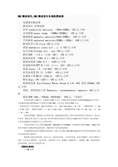
EMC测试项目,EMC测试项目各项收费标准电磁兼容测试费测试项目收费标准传导conduction emission (9kHz-30MHz) 450元/小时功率辐射power clamp (30MHz-300MHz) 450元/小时磁场辐射magnetic emission(9kHz-30MHz) 400元/小时空间辐射radiated emission(30MHz—18GHz) 600元/小时断续传导干扰click 400元/小时谐波harmonics class a,b ,c,d 400元/小时电压闪烁flicker plt 。
pst 400元/小时静电ESD (±0.1—±16。
5kV) 400元/小时辐射抗扰度(1GHz以下) 800元/小时辐射抗扰度(1GHz以上) 1000元/小时快速脉冲群EFT/B (±0。
1-±4。
4kV) 400元/小时浪涌surge (0。
1-6.6kV) 400元/小时传导抗扰度CS(0。
1-30V) 400元/小时抗磁场干扰MS(0—120A/m) 400元/小时断电Dips(0%—100%) 400元/小时振荡波浪涌 Oscillatory Waves Surge 0.1-6。
6kV 波形100kHz 400元/小时谐波、谐间波抗干扰 Harmonic、interharmonic immunity 400元/小时磁场EFM 10Hz—400kHz (EN50366) 500元/一份报告实验室创建于2002年,总面积达2000平方米。
屏蔽室和半电波暗室从德国Frankonia公司进口、全部测试仪器由德国R&S公司和瑞士的EM TEST 公司引进,总投资3500万元.实验室由以下几部分组成:10m半电波暗室一间(24m×18m×9m-L × W × H)、屏蔽控制间一个(8m × 3.5m × 3m)、屏蔽放大器间一个(4m × 3.5m x×3m)、屏蔽测试间两个(8m × 5。
emc静电测试标准EMC(电磁兼容性)静电测试标准是评估电子产品或系统在静电放电(ESD)环境中的性能和可靠性的重要标准。
静电放电是指两个不同电位的物体相互接触或摩擦时,瞬间产生大量电荷的现象。
这些电荷可能会对电子设备产生干扰或损坏,因此进行静电测试是确保设备在真实环境中的稳定性和可靠性必不可少的环节。
一、静电放电模型在EMC静电测试中,通常采用人体模型(HBM)、机器模型(MM)和地模型(GM)三种静电放电模型来模拟不同情况下的静电放电。
1.人体模型(HBM):模拟人类带电体与电子设备之间的放电。
在测试中,使用人体模型来模拟操作员、维修人员或其他与设备交互的人可能引起的静电放电。
2.机器模型(MM):模拟机器或设备之间的放电。
例如,两个不同电位的电路板或电子部件之间的摩擦会产生静电放电。
机器模型用于评估设备在生产线或机器之间的静电放电风险。
3.地模型(GM):模拟设备内部不同电路或组件之间的放电。
地模型主要用于评估设备内部不同部分之间的静电放电风险。
二、静电放电测试标准1.国际电工委员会(IEC):IEC 61000-4-2是最常用的静电放电测试标准之一。
该标准规定了电子产品或系统在进行电磁兼容性测试时应遵循的静电放电抗扰度要求。
它包括三个等级的测试:Level 1、Level 2和Level 3,分别对应不同的电荷量等级。
2.美国联邦航空管理局(FAA):FAA对航空设备的电磁兼容性有特殊要求,其中涉及静电放电测试。
FAA要求设备必须能够承受特定的静电放电等级,以确保其在飞机和其他航空器上的正常运行。
3.其他国家和地区标准:除了IEC和FAA,许多国家和地区都有自己的静电放电测试标准和要求。
例如,中国、欧洲电信标准协会(ETSI)和日本电信标准协会(JTS)等都制定了相应的静电放电测试标准。
三、静电放电测试方法在进行静电放电测试时,通常采用以下步骤:1.确定测试设备和条件:选择适当的测试设备,如静电发生器、示波器、电压表等,并设定适当的测试条件,如测试环境湿度、温度、气压等。
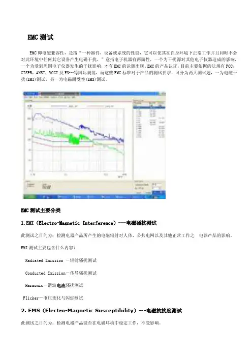
EMC测试EMC即电磁兼容性,是指“一种器件、设备或系统的性能,它可以使其在自身环境下正常工作并且同时不会对此环境中任何其它设备产生电磁干扰。
”意指电子机器有两面性,一个为干扰源对其他电子仪器造成的影响,一个为受到周围电子仪器发生的干扰影响,才有EMC的论题出现。
EMC的产品认证,目前主要依据的法规有FCC,CISPR,ANSI,VCCI及EN┅等国际规范,而这些EMC标准对于产品的测试要求,可分为两大测试题,一为电磁干扰(EMI)测试,另一为电磁耐受性(EMS)测试。
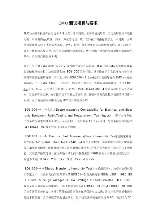
EMC测试主要分类1.EMI(Electro-Magnetic Inte rf erence)---电磁骚扰测试此测试之目的为:检测电器产品所产生的电磁辐射对人体、公共电网以及其他正常工作之电器产品的影响。
EMI测试主要包含什么内容?Radiated Emission -辐射骚扰测试Conducted Emission-传导骚扰测试Harmonic-谐波电流骚扰测试Flicker-电压变化与闪烁测试2. EMS(Electro-Magnetic Susceptibility)---电磁抗扰度测试此测试之目的为:检测电器产品能否在电磁环境中稳定工作,不受影响。
EMS测试主要包含什么内容?ESD-静电抗扰度测试RS-射频电磁场辐射抗扰度测试CS-射频场感应的传导骚扰抗扰度测试DIP-电压暂降,短时中断和电压变化抗扰度测试SURGE-浪涌(冲击)抗扰度测试EFT-电快速瞬变脉冲群抗扰度测试PFMF-工频磁场抗扰度测试杂散定义:指用标准测试信号调制时在除载频和由于正常调制和切换瞬态引起的边带及邻道以外离散频率上的辐射(既远端辐射)。
杂散辐射按其来源可分为传导型和辐射型两种。
传导杂散:指在天线的接头处50欧姆负载上测得的任意离散信号的电平功率。
辐射杂散:测试设备的机壳、结构及互连电缆引起的杂散骚扰。
测试条件首选在电波暗室内进行,或是在户外进行。

EMC测试1静电放电测试(ESD)2群脉冲测试(EFT)3雷击浪涌测试(Surge )EMC测试(IEC 61000系列标准)1静电放电测试(ESD测试)【接触放电】施打方式(Contact Discharge):包含直接接触(Direct Discharge)与间接(耦合)接触(Indirect Discharge)两种方式:直接接触放电方式(Direct Discharge):针对待测物上所有导电表面作测试,Discharge Tip请使用尖头,测试点在待测物本体上,放电枪直接在待测物上放电。
间接(耦合)放电方式(Indirect Discharge):针对待测物水平面(HCP)与垂直面(VCP)作间接(耦合)放电测试,Discharge Tip 请使用尖头,测试点在待测物本体上,放电枪直接在待测物上放电。
水平间接(耦合)接触放电:Horizontal Coupling将待测物置于塑料垫上,距HCP 10cm前,对HCP执行水平间接(耦合)接触放电,静电是以水平面间接耦合方式,传导至待测物。
EUT 四面都需要做测试。
垂直间接(耦合)接触放电:Vertical Coupling将待测物置于塑料垫上,距VCP 前10cm, 对VCP边线线中心点作垂直间接(耦合)接触放电,静电是以垂直面间接耦合方式,传导至待测物。
EUT 四面都需要做测试。
【空间(空气)放电】施打方式(Air Discharge):针对放电枪无法直接、间接接触(Contact)放电的表面或缝隙,则执行Air Discharge。
于电压到达要求值时将Discharge按钮按下,将Discharge Tip(使用圆头)迅速接近测试点(不得破坏待测物),接触后离开,放开按钮,等待电压指示再次达到要求值时,再以相同方式操作,反复执行直到测试完成。
方法:1.按以下参数逐步设置好“静电放电测试仪器”工作步骤:直接接触放电:±4KV(测试金属部位、可接触的金属部件);水平间接(耦合)接触放电:±4KV垂直间接(耦合)接触放电:±4KV空间(空气)放电:±8KV测试电压极性:先打正电压,再打负电压。
EMC的定义http://www.emtest.deEMC就是指:“某个电子或相关产品工作时将与其所处的环境紧密结合为一个整体,这个电子或相关产品不会产生影响到其他产品的电磁干扰。
”换句话说,EMC是用来处理电子产品噪声发射或抑制的。
电磁干扰就是类似雷达发射和抑制的引导干扰。
电磁兼容的概念并不难以理解,难点在于其细节。
让我们稍微深入的对其细节加以解释。
对于EMC的一些专家来说,希望你能谅解我们一些“不科学”的简化。
EMC当然不包括电磁波在生物领域的一些应用。
这是一个涵盖“EMCE”(“E”表示环境)的更广阔的领域,而这并不是今天的话题,同时也非EM TEST涉及的领域。
EMC的历史让我们回顾一下EMC的历史,EMC古老的可能有些让你不可思议。
我们都伴随着自己的历史而生存着,EMC同样如此。
你或许包括许多EMC专家在内,也许并不了解这些来龙去脉。
我们将为你简要介绍一下EMC在欧洲的历史。
接下来的叙述并不十分详细,但这已经或以展示为什么我们今天的EMC世界会是这个样子。
欧洲的通信新纪元始于1892年,当时德国国会投票产生了“关于德国境内的电信法律”。
这是世界第一部关于电磁干扰的法律,同时揭开了电子技术领哉的新纪元。
这部法律同时规定了电磁干扰存在时必须遵循的流程。
那时的人们已经发现线缆之间存在着相互干扰。
这些干扰在电报和电话通信中都不同程度的存在着。
德国电子电报学会于1893年成立,是今天VDE的前身,西门子就是这个组织的创始人之一。
在110年之前,EMC并不是一个大问题,但这种状况在1920年12月22日傍晚发生了改变。
在那个晚上,König Wusterhausen,柏林东南部的广播电台播放了德国信件办公室圣诞音乐会的通知,音乐会是个大事,观众包括住在König Wusterhausen附近的王宫的国王Hermann Müller,他被汽车经过时收音机产生的电磁干扰声音搞得很不高兴,电磁兼容时刻到来了,后来这被称为EMC。
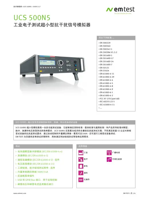
1.静电放电模拟器------------------------------------------------------------------- 3 ESD30N30KV静电放电模拟器------------------------------------------------------------------ 3 DITO静电放电模拟器 ---------------------------------------------------------------------------- 52.汽车瞬变脉冲传导抗干扰信号模拟器 --------------------------------------- 7 UCS200N汽车用电子设备抗扰度测试设备 ------------------------------------------------ 73.电压变化模拟器------------------------------------------------------------------- 11 VDS200N电压变化模拟器--------------------------------------------------------------------- 114.抛负载模拟器---------------------------------------------------------------------- 14 LD200N抛负载发生器 -------------------------------------------------------------------------- 145.连续波模拟器---------------------------------------------------------------------- 18 CWS500N2连续波模拟器 --------------------------------------------------------------------- 18 CWS500N180W连续波模拟器 --------------------------------------------------------------- 206.车载供电系统波形记录发生模拟器----------------------------------------- 23 AutoWave车载供电系统波形记录发生模拟器 ----------------------------------------- 237.共模传导干扰模拟器 ------------------------------------------------------------ 25 CWS500N4共模传导干扰模拟器0Hz(DC)-150kHz -------------------------------------- 258.抗干扰信号模拟器 --------------------------------------------------------------- 27 UCS500N7工业电子测试超小型抗干扰信号模拟器----------------------------------- 27 UCS500N5工业电子测试超小型抗干扰信号模拟器----------------------------------- 30 NetWave三相电源质量抗扰度模拟器----------------------------------------------------- 33 NETWAVE多功能交、直流源 ---------------------------------------------------------------- 33 EFT500N5电快速瞬变脉冲群模拟器------------------------------------------------------- 35 EFT500N8电快速瞬变脉冲群模拟器------------------------------------------------------- 37 MPG200S5汽车微脉冲模拟器 --------------------------------------------------------------- 39 PFS200N汽车电源故障模拟器 --------------------------------------------------------------- 408.振铃波/阻尼震荡波模拟器 ---------------------------------------------------- 44 OCS500N6阻尼振荡波模拟器---------------------------------------------------------------- 44 9.低频模拟器 ------------------------------------------------------------------------- 46 CWS500N310Hz-250kHz低频模拟器-------------------------------------------------------- 46 10.浪涌模拟器 ----------------------------------------------------------------------- 48 VSS500N12电源浪涌模拟器 ------------------------------------------------------------------ 48 VCS500N10浪涌模拟器 ------------------------------------------------------------------------ 49 TSS500N10通讯浪涌模拟器 ------------------------------------------------------------------ 51 TSS500M4通讯浪涌模拟器 ------------------------------------------------------------------- 52 VCS500N8浪涌模拟器-------------------------------------------------------------------------- 54 TSS500M6B通讯浪涌模拟器 ----------------------------------------------------------------- 55 11.谐波和闪烁分析仪-------------------------------------------------------------- 57 DPA500N谐波和闪烁分析仪 ----------------------------------------------------------------- 57 DPA503谐波和闪烁分析仪 ------------------------------------------------------------------- 59 ACS500N66kVA单相AC电压源-------------------------------------------------------------- 60 ACS50320kVA三相AC电压源---------------------------------------------------------------- 61 AIF503S1三相32A闪烁阻抗 ----------------------------------------------------------------- 621.静电放电模拟器ESD30N30KV静电放电模拟器特点空气放电和接触放电的测试电压最高可达30kV放电频率最高可达20Hz可方便更换的R/C网络和放电头泄放功能可测量温度和湿度交流电源供电和直流供电可用电池供电外部触发功能USB接口支持Windows-Vista操作系统的控制和分析软件OptionalfiberopticlinkbetweenESD30Nandcomputer(USBport)应用ESD30N-依照EN/IEC61000-4-2测试等级产生静电放电脉冲人体与物体之间,或两个不同物体之间的静电放电,可能导致敏感电子设备或控件受到持续的干扰乃至破坏。
EMS主要测试项目1. 静电测试(IEC61000-4-2)主要考虑的参数(主要欧洲要求)静电发生器范围:±0.2KV-±16KV;(包含空气和接触放电)波形:上升沿:0.7ns~1ns 周期:60ns测试点:产品正常工作,人手能摸到的地方,都需要施加静电干扰信号备注:现场测试提供整改元件和技术指导2. 辐射抗干扰度测试(IEC61000-4-3)主要考虑的参数(主要欧洲要求)测试频段:80MHz~1000MHz,调制:1kHz或2Hz的AM正弦波进行80%调幅。
3. 快速脉冲群测试(IEC61000-4-4)主要考虑的参数(主要欧洲要求)测试干扰电压:0.2KV~4.4KV产品工作电压:AC80~230V产品工作电流:输入电流16Amax;干扰脉冲波形:5/50ns脉冲群:15ms脉冲串(5K或100Khz),300ms一个周期备注:现场测试提供整改元件和技术指导4. 雷击浪涌测试(IEC61000-4-5)主要考虑的参数(主要欧洲要求)产品工作电压:AC80~230V产品工作电流:输入电流16Amax;测试电压:0.2KV~4.4KV测试波形:开路电压波形 1.2/50us短路电流波形:8/20us 1分钟一次备注:现场测试提供整改元件和技术指导5. 传导抗干扰测试(IEC61000-4-6)主要考虑的参数(主要欧洲要求)产品工作电压:AC80~230V产品工作电流:输入电流16Amax;测试波形:载波频率:0.15~80MHz调制信号:AM 80% 1KHZ调制电压:1V 3V 10V备注:现场测试提供整改元件和技术指导6. 工频磁场测试(IEC61000-4-8)主要考虑的参数(主要欧洲要求)线圈中心磁场强度:100 A/m;7. 电压跌落测试(IEC61000-4-11)主要考虑的参数(主要欧洲要求)测试电压:只能测试AC 220-240输入产品只能测试AC 220-240输入产品。
电机emc 测试标准
电机EMC(电磁兼容性)测试是为了确保电机和电子设备在电磁环境中能够正常运行而进行的测试。
这种测试确保设备既不会产生过多的电磁干扰,也不容易受到外部电磁干扰的影响。
以下是电机EMC 测试的主要标准:
* IEC 61800-3:
* IEC(国际电工委员会)发布了关于可变速电机驱动器EMC 的标准,如IEC 61800-3。
这些标准通常适用于调速电机和驱动器系统。
* CISPR 11:
* 适用于家用、商用和轻工业环境的辐射和导引EMC 标准。
* CISPR 14-1:
* 关于电气和电子设备的辐射和导引EMC 标准。
* EN 55011:
* 适用于工业、科学和医疗设备的辐射和导引EMC 标准。
* EN 61800-3:
* 进一步详细规定了可变速电机驱动器EMC 测试的要求。
请注意,确切的测试标准可能会根据电机的类型、应用领域和国家/地区而异。
在进行EMC 测试之前,建议查阅最新的标准文件,以确保符合适用的要求。
此外,考虑到不同国家和地区可能采用不同的标准,最好根据产品的市场定位选择相应的标准。