UK 06
- 格式:ppt
- 大小:3.92 MB
- 文档页数:28

Bulletin HY11-5715-577/UKInstallation Manual VS111 SeriesPlug-In Amplifier for Proportional ValvesParker Hannifin GmbHHydraulic Controls Division Gutenbergstr. 3841564 Kaarst, GermanyTel.: +49-181 99 44 43 0Fax: +49-2131-513-230E-mail:******************Copyright 2002, Parker Hannifin GmbHPlug-In AmplifierVS111 Series Installation ManualIA UK VS111.INDD 19.06.06 RH NoteThis document and other information from Parker Hannifin GmbH,its subsidiaries, sales offices and authorized distributors provideproduct or system options for further investigation by users havingtechnical expertise. Before you select or use any product or systemit is important that you analyse all aspects of your application andreview the information concerning the product or system in the cur-rent product catalogue. Due to the variety of operating conditionsand applications for these products or systems, the user, throughhis own analysis and testing, is solely responsible for making thefinal selection of the products and systems and assuring that all performance and safety requirements of the application are met.The products are subject to change by Parker Hannifin GmbH atany time without notice.2Parker Hannifin GmbHHydraulic Controls DivisionPlug-In Amplifier VS111 SeriesInstallation Manual3Parker Hannifin GmbH Hydraulic Controls DivisionIA UK VS111.INDD 19.06.06 RHFeatures • Solenoid drive• Simple mounting direct to the valve • Standard voltage or current signal inputs • Control from PLC also possible• Temperature-independent solenoid current • Solenoid connection acc. EN 175301-803 (2+E)•Installation connection acc. EN 175201-804 (6+E)• Conformity to the European EMC standards (CE)The plug-in amplifier VS111 is used to control proportional pressure, directional control, and flow valves.The amplifier is mounted directly on the propor-tional solenoid and secured by a central screw.It supplies a drive current for one proportional so-lenoid. This current is proportional to the command signal at the amplifier input. In conjunction with a proportional valve this allows an infinite adjustmentof a pressure or flow rate.Block diagram4Parker Hannifin GmbH Hydraulic Controls DivisionPlug-In Amplifier VS111 SeriesInstallation ManualIA UK VS111.INDD 19.06.06 RHValve typeValve amplifierDesign SeriesCodeValve type0 without*1 Proportional flow valve2 Proportional DC valve 8 Proportional pressure valveOrdering CodeSupply voltage range [V] 18...32, ripple < 5%Current consumption [A] 0.8Power consumption (at 24V) [VA] 20Input signal ranges input voltage [V]0...+10 / 0...+15, 100kOhm input current [mA] 0...20 / 4...20, 500Ohm Diagnostic output [V] 0.1 ^ 0.2A Reference output[V] 15 ± 5% / max. 5mA Solenoid output current max. [A] 0.8T emperature drift of output current [%] < ± 2%Adjustment ranges Min [%] 0...50 Max [%] 0...100Ramp time range [s] 0.1...8 Dither amplitude range [%] 0...90Dither frequency [Hz]40 / 80Protection classIP65 mounted condition Ambient temperature range [°C]-20 (60)Connection Installation connector 6 + E, EN 175201-804 Solenoid connector 2 + E, EN 175301-803Installation cross sections min. AWG 17Cable outer dimension [mm] max. 11Cable length [m] max. 50Pre-fuse[A]2.0 lag, DIN 41571CharacteristicsAttention: Installation connector has to be ordered separately (order no. HR 2150 2072).*The versions acc. codes 1...8 will be shipped factory set. The version Code 0 needs to be set to the connected valve's characteristics.EN 50081-2EN 55011EN 50082-2 EN 61000-4-2 EN 61000-4-4EN 61000-4-3EN 61000-4-5EMC =VS1110020Plug-In Amplifier VS111 SeriesInstallation Manual5Parker Hannifin GmbH Hydraulic Controls DivisionIA UK VS111.INDD 19.06.06 RHConnection ExamplesSelection and Adjustment OptionsConnection Arrangement Installation ConnectorCommand value given by external signalCommand value given by potentiometer6Parker Hannifin GmbH Hydraulic Controls DivisionPlug-In Amplifier VS111 SeriesInstallation ManualIA UK VS111.INDD 19.06.06 RHDimensionsAdjustment Instruction Note:For all following adjustments the potentiometer "Dither signal" has to set fully counterclockwise first. The solenoid current measured at the diag-nostic output should be observed (plug-in amplifier connected to the solenoid). Please take notice of the adjustment sequence!1. MIN current setting- C ommand signal zero (0V/0mA) - T urn the potentiometer "MIN current" clockwise, until the required valve adjustment is reached.2. MAX current setting- C ommand signal maximum (10V/15V/20mA) - T urn the potentiometer "MAX current", until the required valve adjustment is reached.Direction to trouble shootingThe required max. current can just keep constant until the condition Max current (A) =Supply voltage (V) 2Vactual solenoid spool resistance (Ohms)*3. Ramp time setting- Adjust the response time by variationof the potentiometers "Ramp up" and "Ramp down", until the required transi-tion behaviour is reached.4. Dither adjustment- Select dither frequency aac. solenoid/ valve type, with jumper B2 = 80 Hz without jumper B2 = 40 Hz- Feed in approx. 40% command signal. - Turn the potentiometer "Dither signal" max. clockwise, until an oscillating is audible within the hydraulic system.will be keeped. This means for example, that if a solenoid spool of 24V/0.8A will be connected to the amplifier, the supply voltage should reach approx. 30V .*the resistance of the spool increases by warming for up to 40%.Plug-In Amplifier VS111 SeriesInstallation Manual7Parker Hannifin GmbH Hydraulic Controls DivisionIA UK VS111.INDD 19.06.06 RHInstallation Guideto Provision of Electromagnetic CompatibilityPower SupplyThe utilized power supply has to comply with the EMC-standards (CE-sign, certificate of conformity).Relays and solenoids operating from the same supply circuit has to be fitted by surge protection ele-ments.Wiring CableThe wiring cable between the control cabinet and the valve has to be shielded. The wiring has to be installed from a 7wire cable that utilizes a common shielding and a cross section of min. AWG17. The capacity should not exceed a value of approx. 130pF/m (wire/wire). The maximum cable length is 50 m. No power current lines may be placed in parallel to the valve's wiring cables. The cable shield has to be connected to the connector pin 2. The earth pin of the connector has to be installed as separate wire within the cable to the cabinet and should there be connected to the Earth Ground potential.Example。

Cherry 系列航空铆钉介绍Cherry Maxibolt 钛合金系列盲铆钉材质:钉体材质,钛合金;钉杆材质,钛合金;锁紧环材质,A-286耐蚀钢,铬镍铁合金头型:100°沉头;平头;130°沉头直径:-04、-05、-06、-08产品系列:CR7770S;CR7771S;CR7772S;CR7773S;CR7774S编号举例:CR7770 S -05 -04 W,说明如下CR7770:铆钉基本编号S:锁紧环安装类型,有S型,U型和’-’型三种-05:铆钉直径,5/32’-04:铆接厚度编码,4/16’W:铆钉的图层方式。
无编码表示无图层;“BE”表示铝图层(NAS4006和BMS10-85标准);“D”表示IVD铝图层;“EE”表示铝图层;“HK”表示Hi Kote图层;“W”表示阳极处理蓝色图层Cherry Maxibolt 钛合金系列盲铆钉详细资料请电话咨询!Cherry Maxibolt系列盲铆钉材质:钉体材质,合金钢;钉杆材质,合金钢;锁紧环材质,耐蚀钢头型:100°沉头;平头直径:-04、-05、-06、-08、-10产品系列:CR7310系列;CR7620系列;CR7311系列;CR7621系列;CR7340系列;CR7650系列;CR7341系列;CR7651系列编号举例:CR7770 S -05 -04 W,说明如下CR7310:铆钉基本编号S:锁紧环安装类型,有S型,U型和’-’型三种-05:铆钉直径,5/32’-04:铆接厚度编码,4/16’W:铆钉的图层方式。
无编码表示无图层;“BE”表示铝图层(NAS4006和BMS10-85标准);“D”表示IVD铝图层;“EE”表示铝图层;“HK”表示Hi Kote图层;“W”表示阳极处理蓝色图层Cherry Maxibolt系列盲铆钉详细资料请电话咨询!Cherry Max系列盲铆钉材质:5056铝钉体/铝合金钉杆(50KSI抗剪切力);5056铝钉体/耐蚀钢钉杆(50KSI抗剪切力);monel 钉体/耐蚀钢钉杆(75KSI抗剪切力);镍合金600钉体/Inconel X-750钉杆(75KSI抗剪切力)头型:MS20470标准圆头;MS20426标准100°沉头;NAS1907标准100°沉头;平角沉头;120°沉头直径:-04、-05、-06、-08产品系列:CR3212、CR3213、CR3214、CR3222、CR3222TU、CR3223、CR3223TU、CR4223、CR3242、CR3242A-4-02.5、CR3242BT-4-02、CR3243、CR3245、CR3246、CR3252、CR3252TU、CR3253、CR3253HS、CR3253TU、CR3255、CR3280、CR3281、CR3522、CR3522TU、CR3523、CR3523HC-5、CR3523TU、CR3524、CR3552、CR3552、TUCR3553、CR3553-5-02.5、CR3553-5-03.5、CR3553TU、CR3555、CR3556、CR3822、CR3823、CR3852、CR3853编号举例:CR3 24 2 -6 -04 W,说明如下CR3:铆钉基本编号24:铆钉类型和材质2:头型,偶数表示平头;奇数表示沉头-6:铆钉直径,5/32’-04:铆接厚度编码,4/16’W:铆钉的图层方式。
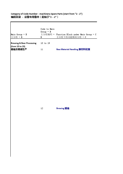
Category of Code Number - machinery Spare Parts (start from "2 - 2")编码目录-设备专用备件(起始于“2-2”)13Fermentation 发酵14Filtration 过滤15Yeast Handling 酵母处理16Bright Beer Tank 清酒罐17Utility Installations for B&P/Packaging 酿造/包装车间公用设施22Canning Line 听装线23PET Bottling Line PET瓶装线24Asceptic Filling Line 无菌灌装线25Kegging Line 桶装线32CO2 Recovery Plant/N2 Generation Plant 二氧化碳回收单元/N2发生器33Compressed Air Plant 压缩空气单元34Steam/High Temperature Hot Water Boiler Plant 蒸汽/高温热水锅炉单元35Electricity Supply 供电系统36Raw Water Treatment Plant/Water Puming Station 天然水处理单元/水泵站37Waste Water Treatment Plant 污水处理单元42验室设备MachineSerial Number 机器设备系列号Line Capacity 生产线能力Weak Wort & Trub Tanks 弱麦汁及热凝固物贮罐14 Wort Pre-Heater 麦汁预热器15 Wort Chiller 冷麦计薄板换热器16 Wort Pumps 麦汁泵17 CIP System CIP清洗系统18 Wort Aeration Unit 麦汁冲氧装置19 Spent Grain Silo & its Assessories 麦糟罐及其附属设施20 2nd Steam Recovery System 二次蒸气回收系统21 Automation Control Unit 糖化自控及计量系统 (例如,中央控制操作系统SCADA)22 Main Distribution & ControlSwitchboard/Control Components (Sensing, Counting & Measuring) 主要配电及开关切换/控制组件电柜(含自控:传感器,计数和测量)90 Others 其它951Fermentation Tanks WithFlowplate/Matrix Valve 发酵罐及接管板/阀阵系统01 Beer Cooler 倒罐冷却设备02 Sampling Pipework System 取样管道系统03 CIP Sytem CIP清洁系统04 Automation Control Unit 酿造自控系统(例如,中央控制操作系统SCADA)05 Main Distribution & ControlSwitchboard/Control Components(Sensing, Counting & Measuring) 主要配电及开关切换/控制组件电柜(含自控:传感器,计数和测量)90 Others 其它951Beer Treatment Coolers 倒罐设备01Kieselguhr Filter 硅藻土过滤机02Spent Kieselguhr System 废硅藻土处理装置03Filter Cooler Beer Cooler 激冷设备/啤酒薄板冷却器04Beer Centrifuge 啤酒离心机05High Gravity De-Brewing System 高浓稀释设备06Water De-aeration Plant 脫氧水系统07Steriled Water Plant 无菌水系统08Beer Buffer Tanks 啤酒缓冲罐09Dosing Units for Additives 添加剂添加设备10CO2 Dosing/Aeration Units 二氧化碳添加/冲氧装置11 Beer Recovery Equipments (First & Last Running/FOB) 啤酒回收装置12 CIP System CIP清洁装置13 Automation Control Unit 自控及计量系统(例如,中央控制操作系统SCADA)14 Main Distribution & ControlSwitchboard/Control Components (Sensing, Counting & Measuring) 主要配电及开关切换/控制组件电柜(含自控:传感器,计数和测量)90 Others 其它951Yeast Storage Tanks Including Harvest & Pitching Devices 酵母贮存系统(含酵母回收/添加装置)01 CIP for Yeast Storage Tanks 酵母贮存系统的CIP清洁装置02 Yeast Propagator 酵母扩培系统03 Spent Yeast Handling 废酵母处理设备04 Main Distribution & ControlSwitchboard/Control Components (Sensing, Counting & Measuring) 主要配电及开关切换/控制组件电柜(含自控:传感器,计数和测量)90 Others 其它951Bright Beer Tanks With Flowplat/Matrix Valve 清酒罐及接管扳阀阵系统01 Constant Pressure Beer Pump 清酒恆压泵装置02 Automation Control Unit 自控及计量系统03 Others 其它951Compressed Air Supply 供压缩空气装置01N2 Supply 供氮气装置02CO2 Supply 供CO2装置03Steam/HTHW Supply 供蒸汽/高温热水装置04Cooling Supply 制冷装置05Beer/Yeast/Water Pipework 啤酒/酵母/水供给管道装置06Sampling Devices 取样装置07Others 其它95Crown Cork Crusher 瓶盖粉碎机26Main Distribution & ControlSwitchboard/Control Components(Sensing, Counting & Measuring) 主要配电及开关切换/控制组件电柜(含自控:传感器,计数和测量)90CIP System CIP 清洁系统27Others 其他951Beer Buffer Tank 啤酒缓冲罐00Beer Cooler/Beer Pump/GAF Filter 啤酒薄板冷却器/酒泵/袋式捕捉器01Depalletizer 卸垛机02Can Rinses 冲罐机03Can Filler 易拉罐灌装机04Can Seamer 易拉罐封盖机05Tunnel Pasteurizer/Bottle Warmmer 隧道式巴氏杀菌机/暖瓶机06Fill Height Monitor/Full Crate or CartonMonitor 液位测检仪/滿箱测检机07High Pressure Air blowing Sysem 高压吹气装置08Carton/Tray Packers 纸箱装箱机09Shrink Wrapper 膜包机10Palletizer 码垛机11Date Coder 喷码机12Conveyor & Elevator System/Combiner &Channelizer/Lubrication System 输送带及垂直升降系统/合併和分行/润滑系统13Can Crushher 易拉罐压榨机14Main Distribution & ControlSwitchboard/Control Components(Sensing, Counting & Measuring) 主要配电及开关切换/控制组件电柜(含自控:传感器,计数和测量)90CIP System CIP 清洁系统15Others 其他951Beer Buffer Tank 啤酒缓冲罐00Beer/Water Membance Filtration Systems啤酒/水膜过滤系统01Water TreatmentSystem/Steriled WaterPlant 水处理系统/无菌水处理设备02Steriled Plant Room Facilities 无菌间设施03Beer Cooler/Beer Pump/GAF Filter 啤酒薄板冷却器/酒泵/袋式捕捉器04Blow Moulder 吹瓶机05Bottle Rinser 冲瓶机06Crown Cork/Cap Delivery System withDeinfection Unit 带杀菌单元的皇冠盖/易拉罐盖输送系统07Decapper 旋盖机08PET Bottle Filler PET瓶灌装机09Bottle Capper/Crowner 瓶子压盖机10Tunnel Pasteurizer/Bottle Warmmer 隧道式巴氏杀菌机/暖瓶机11High Pressure Air blowing Sysem 高压吹气装置12Fill Height Monitor/Full Crate or CartonMonitor 液位测检仪/滿箱测检机13Labeler 贴标机14Carton Packers 纸箱装箱机15Shrink Wrapper 膜包机16Palletizer 码垛机17Date Coder 喷码机18Conveyor & Elevator System/Combiner &Channelizer/Lubrication System 输送带及垂直升降系统/合併和分行/润滑系统19Main Distribution & ControlSwitchboard/Control Components(Sensing, Counting & Measuring) 主要配电及开关切换/控制组件电柜(含自控:传感器,计数和测量)90CIP System CIP 清洁系统20Others 其他951Beer Buffer Tank 啤酒缓冲罐00Steam Generator/CL2 Generator/OzoneGenerator 蒸汽发生器/CL2发生器/臭氧发生器01Beer/Water Membance Filtration Systems啤酒/水膜过滤系统02Water TreatmentSystem/Steriled WaterPlant 水处理系统/无菌水处理设备03CIP System CIP 清洁系统04Steriled Plant Room Facilities 无菌间设施05Beer Cooler/Beer Pump/GAF Filter 啤酒薄板冷却器/酒泵/袋式捕捉器06Bulk Glass Depalletizer 散瓶卸垛机07Crate Depalletizer 塑箱卸垛机08Crate Washer 洗箱机09Bottle Pre-Washer 预洗瓶洗瓶机10Bottle Washer 洗瓶机11Empty Bottle Inspector 空瓶验瓶机12Crown Cork/Cap Feeding System withDeinfection Unit 带杀菌单元的皇冠盖/易拉罐盖输送系统13Decapper 旋盖机14Bottle Rinser 冲瓶机15Bottle Filler 玻璃瓶灌装机16Bottle Capper/Crowner 瓶子压盖机17Tunnel Pasteurizer/Bottle Warmmer 隧道式巴氏杀菌机/暖瓶机18Fill Height Monitor/Full Crate or CartonMonitor 液位测检仪/滿箱测检机19High Pressure Air blowing Sysem 高压吹气装置20Crate Unpacker/Packer 塑料箱卸箱/装箱机21Labeler 贴标机22PSL Labeler 压敏标(塑料)贴标机30Carton Packers 塑料箱/纸箱装箱机23Shrink Wrapper 膜包机24Palletizer 码垛机25Date Coder 喷码机26Conveyor & Elevator System/Combiner &Channelizer/Lubrication System 输送带及垂直升降系统/合併和分行/润滑系统27Spent Caustic Recovery system/BeerRecovery System/Water Recovery System残醎回收/残酒回收/溢水回收28Main Distribution & ControlSwitchboard/Control Components(Sensing, Counting & Measuring) 主要配电及开关切换/控制组件电柜(含自控:传感器,计数和测量)90CIP System CIP 清洁系统29Others 其他951Beer Buffer Tank 啤酒缓冲罐00Flash Pasteurizer 瞬时杀菌机01Depalletizer 卸垛机02External Keg Washer 洗桶机03Washing/Kegging Machine 洗桶/灌装机04Labeler 贴标机05Keg Turner 翻桶机06Keg Capper 封盖机07Others 其它951CO2 Recovery Unit Including Cooling Compressor System 二氧化碳回收系统(含冷却设备)01 CO2 Balloon Unit 贮存气囊02 CO2 Evaporator with Pressure Regulation Station 二氧化碳蒸发器(含穩压输出装置)03 Evaporative Condenser/Cooling Tower 蒸发冷凝器/水塔冷却设施04 CO2 Liquid Storage Tank 二氧化碳贮罐系统05 Cylinder Filling Station 二氧化碳气瓶灌装设备06 CO2 Leakage Detector/Ventilation Facility二氧化碳洩漏报警装置/通风设施07 N2 Generation Unit Including Cooling Compressor System 制氮机(含冷却设备)08 N2 Buffer Tank 氮气贮罐09 Gas Filtration System 气体过滤系统10 Gas Pipework System 气体管道设施11 Gases Distribution Manifold 供气分配管束12 CO2/N2 Pipework System 二氧化碳/氮气管道系统13 Automation Control Unit 自控及计量系统(例如,制冷负荷中央控制系统)80 Main Distribution & ControlSwitchboard/Control Components (Sensing, Counting & Measuring) 主要配电及开关切换/控制组件电柜(含自控:传感器,计数和测量)90 Others 其它951Air Compressor 空压机01Air Dryer 空气干燥机02Air Purifier 空气淨化机03Air Receiver 空压贮罐04Gas Filtration System 气体过滤系统05Equipment Cooling Water System 设备冷却水系统06Compressed Air Pipework System 压缩空气管道设施07Compressed Air Distribution Manifold 供气分配管束08Compressed Air Pipework System 空压管道系统09Automation Control Unit 自控及计量系统(例如,制冷负荷中央控制系统)80 Main Distribution & ControlSwitchboard/Control Components (Sensing, Counting & Measuring) 主要配电及开关切换/控制组件电柜(含自控:传感器,计数和测量)90 Others 其它951Steam/High Temperature Hot WaterBoiler Unit 蒸汽/高温热水锅炉01 Chimney/Water Scrubber for SO2 & Soot Removal 煙囱/脱硫除尘系统02 Water Treatment Unit 软水处理系统03 Pump Station Including Steam Pump 水泵设备(含蒸汽否)04 O2 Scavenger 除氧装置05 Coal Handling Facilities 燃煤处理系统(含输送、破碎和秤重设备)06 Steam Vessels 蒸汽贮罐07 Coal Sludge Handling Facilities 煤渣处理没施08 Steam Condensate Recovery System 蒸汽冷凝水回收系统09 Steam/HTHW Distribution Manifold 供汽分配管束(含穩压装置及安全阀系统)10 Diesel/Oil Supply Installation 燃油供应装置11 Steam Pipework System 蒸汽管道设施13 Automation Control Unit 自控及计量系统(例如,制冷负荷中央控制系统)80 Main Distribution & ControlSwitchboard/Control Components (Sensing, Counting & Measuring) 主要配电及开关切换/控制组件电柜(含自控:传感器,计数和测量)90 Others 其它951High-Tension Switchboard 高压开关切换电柜01 Power Transformer 变压器02 Low-Tension Main Distribution Switchboard 低压主配电柜03 Distribution Cabinets 车间配电柜04 Power Factor Correction 功率因素修正装置05 Cable & Wiring/Cable Tray & Ladder 电缆/桥架06Equipotential Bonding 等电位连接07Standby Generator 后备发电机组08Power Energy Saving System 电力节能系统09Others 其它951Submerged Pump Station 深井水泵系统01Water Buffer Tanks 水缓冲罐02Water Pump Stations 水泵站03Water Softening Plant 软水处理系统04Reverse Osmosis Treatment Unit 純水处理系统05Sedimentary & Filtering Unit 沉淀及过滤设备06Chlorination/Sterilization Plant 氯气添加/消毒设备07Sand Filter 石英沙过滤器08Activated Carbon Filter 活性碳过滤器09Processed Water Tanks 酿造水贮罐10Chemical Dosing/Cleaning Unit 化学品添加/清洁装置11Water Distribution Manifold 供水分配管束(含穩压/恆压或恆流装置及安全阀系统)12Water Pipework System 水管道设施13Main Distribution & ControlSwitchboard/Control Components(Sensing, Counting & Measuring) 主要配电及开关切换/控制组件电柜(含自控:传感器,计数和测量)90Others 其它951Waste Water Treatment System 污水处理系统01 Spent Caustic/Acid Receiver 残酸碱回收及中和设备02 High Preesure/Flow Air Supply 空压供应系统03 Methane Collection/Disposal Unit 甲烷收集/处理设备04 Chemical Dosing Unit 化学品添加装置05 Pump/Submerged Pump 水泵/潜水泵06 Belt Press 压滤机07 Sewage Pipework System 污水管道系统09 Automation Control Unit 自控及计量系统80Coal Quality Analyser/Sampling Crusher全自动煤分析仪/制样粉碎机27 Incubator 恒温培养箱28 Oven 恒温干燥箱29 Steriliser 干热灭菌箱30 Autoclave 高压消毒器31 Microscope 显微镜32 Centrifuge 离心机33 Water Distillator 蒸馏水器34 Ice Water Bath 冰水柜35 Cross Beater Mill 粉碎机36 EBC Mill EBC 粉碎机37 Sampling Crusher 制样粉碎机38 Jaw Crusher 鄂式破碎机39 Mincer 实验麦芽标准粉碎机40 Hop Mill 啤酒花粉碎机41 Vacuum Pump 真空泵42 Carlsberg Flask 卡氏罐43 Standard/Super Clean Bench 标准/超净化无菌工作台44 General Working Bench With Its Accessories 工作台及其附属配置设施45 Mutifunction Shaker 多用振荡器/摇床46 Shaking Instrument 摇瓶仪47 Pycnometer Washer 比重瓶清洗仪48 Magnifying Glass With Light 带灯放大镜49 Diacetyl Aparatus 双乙酰蒸馏仪50 Elecyric Agitator & Heater 电磁加热搅拌器51 Electric Agitator 磁力搅拌器52 Refrgerator 冰箱53 Malt Modification Analyser 溶解度分析仪54 Friabilimeter 脆度仪55 Disc Sander 麦粒砂膜机56 Digital Burette 电子滴定仪57 Plastic Bag Seal 封袋加热器58 Oxioid Anaerobic Jar 厌氧罐59 Steam Generator 蒸汽产生器60 Blow Lamp for Steam Generator 蒸汽产生器喷灯61 Blowtorch 喷枪62 Distillation for SO2 二氧化硫蒸馏仪63 Electromantle 窝式电炉/电热套64 Transformer 电压转换器65 Membrane Filtration 微膜抽滤器66 Glasswares 玻璃器具67 Others 其它952Pasteurizer Monitor 巴氏杀菌监测仪01Double Seam Monitor 二重卷边监测仪02Video Monitor 视频监测仪03Seam Thickness Gauge 卷边厚度测定仪04Seam Height Gauge 卷边长度测定仪05Plate Thickness Gauge 铝片厚度测定仪06Can Height GaugingDevice 罐高测定仪07Enamel Rater 内喷涂检测仪08Pressure Test Apparatus 玻璃瓶耐内压测定仪09Impact resistance test Apparatus 玻璃瓶抗冲击测定仪10Crown Cork Tester 瓶盖气密性测定仪11Crown Height Gauge 瓶盖高度百分表12Digimatic Heightgage 瓶高测定仪13Go-Nogo Gauge 瓶盖规尺14Crimp Diameter Gauge 瓶盖外径规尺15Skirt Gauges 瓶盖尺寸规尺16Vernier Caliper 游标卡尺17Oxygen Analyzer 测氧仪18Indicating Devices 显示器19Sensor/Transmitter Devices 感然/传感器20Flow Chamber 溶氧取样器21Sampling Device for DO 溶氧取样器22Manometer 显示仪表23Sampling Device for Air Headspace 顶空空气取样器24Air in Headspace Analyzer25Light Box Visual Haze 目测浊度灯箱26Universal Can Stripper 开罐器27Lab. Crowner 手工封盖机28Bottle Turner 旋瓶仪29UV-Lamp 紫外灯30Light Box Labels 标签检测灯箱31RUB Tester 标签摩擦仪32Bar Code Quick-Check 条码解读器33Digital Thermometer 数字温度计34Bottle Axis Deviation Digital Instrument啤酒瓶数显轴偏差仪35Bottle Thickness Tester (Bottom & SideWall) 啤酒瓶数显底/壁厚度仪36Carton Compression Strength Tester 纸箱抗压强度检测仪37Timer 计时器(秒表)38Others 其它95。


S m a l l T o o l I n s t r u m e n t s a n d D a t a M a n a g e m e ntIntuitive buttons and layoutInside/outside diameters, maximum/minimum heights and displacement can be measured using a standard probeID measurement OD measurementPower supply• Four alkaline AA/LR6 batteries (standard accessories)and improves data reliability and operational efficiency.• Pressing a button on the grip activates the internal air pump. The base rises on a cushion of air and is able to be moved smoothly over the surface plate.Note: Measurements should not be madeQM-Height measures height, height difference (step), inside/outside widths, inside/outside diameters, circle pitch, free-form surface maximum/minimum heights and height difference by scanning measurement Two subdisplay modes display the value from the previous measurements or the value from the zero/origin point. Origin points can also be set from hole centers.*Scanning measurement stroke is approx. 1 mm above and below from the start point of measurement.measurementMin. valueMax. valueUpper row: Meas. value (Height or Dia.) Lower row: Height difference CHeight A Height BHeight A and height B from the surface plate will be displayed.6Centralized Data Management600 mm stroke typeWithout air-suspension: 518-242, 518-243With air-suspension: 518-246, 518-247W i re le ssTransmitterU-WAVE-TIP67 type: 02AZD730G Buzzer type: 02AZD880GMisinput due to manual input can be eliminated and dramatically improve operational efficiency.PCNote: Use a commercially available USB micro-cable (for communication use only).• The USB communication driver can be downloaded from the Mitutoyo website. https://www.mitutoyo.co.jp/eng/USB outputReceiver02AZD810DU-WAVE-RUSB-ITN-DUSB Input Tool Direct06AFM380DMeasurement Data Network SystemMeasurLink ® is an IoT platform for quality management that realizes “Visualization of Quality” by enabling real-time data collection from the networked Digimatic gages and global control and analysis.MeasurLink ® is a registered trademark of Mitutoyo Corporation in Japan and Mitutoyo America Corporation in the United States.06AFZ050 USB cable (A-microB)Digimatic output7Order No. Item nameSmall printer equipped with Data Logger 264-505A DP-1VA LOGGER 936937Digimatic connecting cable (1 m) 965014Digimatic connecting cable (2 m) 06AFZ050USB cable (A-microB) Measurement Data Input Unit 06AFM380D USB Input Tool Direct USB-ITN-D Measurement data wireless communication system 02AZD730G U-WAVE-T (Transmission unit) (IP67 type)02AZD880G U-WAVE-T (Transmission unit) (Buzzer type)02AZD790D U-WAVE-T dedicated cable (Standard use)02AZE140D U-WAVE-T dedicated cable (For foot switch)02AZD810D U-WAVE-R receiver 02AZE990U-WAVE mounting plateMeasurement data collection software for Excel USB-IT PAK V2.1Measurement data network system MeasurLinkOptional parts that enable centralized data managementContact points for a wide range of measurements (Refer to page 8.)No.Order No. Item descriptionDepth probe (1)12AAC072Depth probeInterchangeable contact points for ø5 stepped probe (2)957261ø2 mm ball (coaxial type)(3)957262ø3 mm ball (coaxial type)(4)957263ø4 mm ball (coaxial type)(5)957264ø14 mm disk (6)957265ø20 mm disk (7)12AAA788ø4 mm ball (eccentric type)(8)12AAA789ø6 mm ball (eccentric type)Special holder (9)12AAA792Holder for dial indicator (10)12AAA793Holder (Long)AC Adapter06AFZ950JAAD620JA for Japan/U.S.06AFZ950DAD620D for the EU 06AFZ950EAD620E for the UK 06AFZ950KAD620K for Korea 06AEG180DC AD620DC for China Others 05HZA1439x9 mm adapter (clamp underneath is required)05GZA033Clamp (for 9x9 mm adapter)05HZA144 6.35x12.7 mm adapter (clamp underneath is required) 901385Clamp (for 6.35x12.7 mm adapter) 05HZA173Scriber*Note: A gage block may be required for the zero-setting depending on theprobe or contact point to be used.* Used for measurements, cannot be used for scribing.WiredcommunicationWiredcommunicationDigimatic output936937 Digimatic connecting cable (1 m) 965014 Digimatic connecting cable (2 m)Data logger function gives ability to store up to 1000 records of measurement data.Digimatic Mini-Processor 264-505ADP-1VA LOGGERDigimatic output350 mm stroke typeWithout air-suspension: 518-240, 518-241With air-suspension: 518-244, 518-2451)2)3)4)5)6)7)8)9)10)(94.6)ø7147ø14ø1947901) 12AAC072Depth probe8) 12AAA789ø6 mm ball (eccentric type)3) 957262ø3 mm ball (coaxial type)4) 957263ø4 mm ball (coaxial type)5) 957264ø14 mm disk6) 957265ø20 mm disk9) 12AAA792Holder for dial indicatorHolder (Long)Contact points for a wide range ofmeasurements7) 12AAA788ø4 mm ball (eccentric type)2) 957261ø2 mm ball (coaxial type)*1 The indication accuracy and repeatability represent the values obtained from the height measurement of a flat surface using the standard holder with ø5 ball contact point. In the case of diameter, minimum (maximum) value, circle pitch or difference measurement, measuring errors may be larger than the accuracy ratings listed in the table due to variations in measuring force during a scanning measurement, which differs from height measurement.*2 Indicates the value obtained from the measurement of a straight surface placed perpendicular to the the base reference surface using the Lever Head (MLH-521) and Mu-checker (M-551).*3 Requires special communication driver and software. Consult your local Mitutoyo Sales Office for details.These can be downloaded from the Mitutoyo web site. https://www.mitutoyo.co.jp/eng/contact/products/usb/index.html *4 When using a model with the air-suspension feature, it is advisable to use a JIS 1 class, or higher, surface plate. Using on surfaces with scratches or unevenness may prevent the system operating to the specified performance. *5 The AC adapter cannot be used to recharge rechargeable batteries.*6 Battery life depends on the operating conditions. In particular, it is more economical to use the optional AC adapter to power the instrument if the application requires prolonged use of the air-suspension feature.518-247518-245Standard accessoriesOrder No.Item12AAA715Probe diameter calibration block 05HZA148ø5 mm stepped probe—Alkaline batteries x 4 (AA/LR6)64PKA130B 64PKA129BSensor Systems Test Equipmentand Seismometers Digital Scale and DRO SystemsSmall Tool Instrumentsand Date ManagementMin-house on a sub-contract basis.Mitutoyo America CorporationOne Number to Serve You Better1-888-MITUTOYO (1-888-648-8869)M3 Solution Centers:Aurora, Illinois (Headquarters)Boston, MassachusettsCharlotte, North CarolinaCincinnati, OhioDetroit, MichiganLos Angeles, CaliforniaBirmingham, AlabamaSeattle, WashingtonHouston, Texas0719-00 • Printed in USA • Aug. 2019©219MitutoyoAmericaCorporationFind additional product literatureand our product catalogNote: All inform ation regarding our products, and in particular the illustrations, drawings, dim ensional and perform ancedata contained in this printed matter as well as other technical data are to be regarded as approximate average values. Wetherefore reserve the right to make changes to the corresponding designs. The stated standards, similar technical regulations,descriptions and illustrations of the products were valid at the time of printing. In addition, the latest applicable version of ourGeneral Trading Conditions will apply. Only quotations submitted by ourselves may be regarded as definitive. Specificationsare subject to change without notice.Mitutoyo products are subject to US Export Administration Regulations (EAR). Re-export or relocation of our products mayrequire prior approval by an appropriate governing authority.Trademarks and RegistrationsDesignations used by companies to distinguish their products are often claimed as trademarks. In all instances where MitutoyoAm erica Corporation is aware of a claim, the product nam es appear in initial capital or all capital letters. The appropriatecompanies should be contacted for more complete trademark and registration information.。
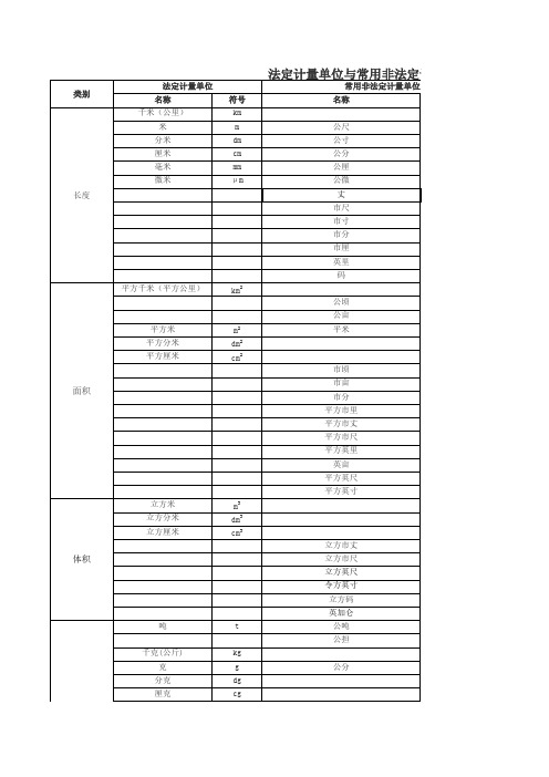
单位名称单位符号单位名称单位符号米m 费密1费密=1 fm=10-15 m 海里n mile埃Å 1 Å=0.1nm=10-10 m 码yd1 yd=0.914 4 m [市]里1里=500 m 丈1丈=(10/3) m=3.尺m寸1尺=(1/3) m=0.3[市]分ft m英尺in 1寸=(1/30) m=0.03英寸mile m英里mil1分=(1/300) m=0.00密耳m1 ft=0.304 8 m 1 in=0.025 4 m 1 mile=1 609.344 m 1 mil=25.4×10⁻⁶ m平方米m 2公亩a 1 a=100 m 2公顷hm 2①平方英尺ft 2 1 ft 2=0.092 903 0 m 2平方英寸in 2 1 in 2=6.451 6×10⁻⁴ m 2平方英里mile 2 1 mile 2=2.589 99×106 m 2平方米m 2平方码yd 2 1 yd 2=0.836 127 m 2公顷hm 2英亩acre 1 acre=4 046.856 m 2亩1亩=10 000/15 m 2=666.6 m 2立方米m 3立方英尺ft 3 1 ft 3=0.028 316 8 m 3升L ,(1)令方英寸in 3 1 in3=1.638 71×10-5 m 3立方码yd 3 1 yd 3=0.764 554 9 m 3英加仑UKgal 1 UKgal=4.546 09 dm 3美加仑USgal 1 USgal=3.785 41 dm 3英品脱UKpt 1 UKpt=0.568 261 dm 3美液品脱USliqpt 1 USliqpt=0.473 176 5 dm 3美干品脱USdrypt1 USdrypt=0.550 610 5 dm 3美桶1美桶=158.987 3 dm 3(用于石油)英液盎司UKfloz 1 UKfloz=28.413 06 cm 3美液盎司USfloz 1 USfloz=29.573 53 cm 3英尺每秒ft/s 1 ft/s=0.304 8 m/s 英里每[小]时mile/h 1 mile/h=0.447 04 m/s 英尺每二次方秒ft/s 2 1 ft/s=0.304 8 m/s 2伽Gal 1 Gal=0.01 m/s 2千克(公斤)kg 磅lb 1 lb=0.453 592 37 kg 吨t 英担cwt 1 cwt=50.802 3 kg 原子质量单位u英吨ton 1 ton=1 016.05 kg 短吨sh ton 1 sh ton=907.185 kg 盎司oz 1 oz=28.349 5 g 格令gr 1 gr=0.064 798 91 g 夸特qr, qtr1 qr=12.700 6 kg [米制]克拉1米制克拉=2×10⁻⁴ kg常用法定计量单位及其换算质量体积速度米每秒m/s 加速度米每二次方秒m/s 2物理量名称法定计量单位非法定计量单位单位换算长度面积体积质量千克每立方米kg/m 3磅每立方英尺lb/ft 3 1 lb/ft 3=16.018 5 kg/m 3[质量]密度吨每立方米t/m 3磅每立方英寸lb/in 3 1 lb/in 3=27 679.9 kg/m 3千克每升kg/L 盎司每立方英寸oz/in 3 1 oz/in 3=1 729.99kg/m 3质量体积立方英尺每磅ft 3/lb 1 ft 3/lb=0.062 428 0 m 3/kg 比体积立方英寸每磅in 3/lb 1 in 3/lb=3.612 73×10-5 m 3/kg 线质量千克每米kg/m 旦[尼尔]den 1 den=0.111 112×10-6 kg/m 线密度特[克斯]tex磅每英尺lb/ft 1 lb/ft=1.488 16 kg/m 磅每英寸lb/in 1 lb/in=17.855 0 kg/m 磅每码lb/yd 1 lb/yd=0.496 055 kg/m 磅二次方英尺lb • ft 2 1 lb • ft 2=0.042 140 1 kg • m 2磅二次方英寸lb • in 2 1 lb • in 2=2.926 40×10-4 kg • m 2盎司二次方英寸oz • in 2 1 oz • in 2=1.829 00×10-5 kg • m 2磅英尺每秒lb • ft/s 1 lb • ft/s=0.138 255 kg • m/s 达因秒dyn • s 1 dyn • s=10-5 kg • m/s 达因dyn 1 dyn=10-5 N 千克力kgf 1 kgf=9.806 65 N 磅力lbf 1 lbf=4.428 22 N 吨力tf 1 tf=9.806 65×103 N 盎司力ozf 1 ozf=0.278 014 N 磅达pdl1 pdl=0.138 255 N动量矩角动量力矩千克力米kgf • m 1 kgf • m=9.806 65 N • m 力偶矩磅力英尺lbf • ft 1 lbf • ft=1.355 82 N • m 转矩磅力英寸lbf • in 1 lbf • in=0.112 985 N • m 达因厘米dyn • cm 1 dyn • cm=10-7N •m盎司力英寸ozf • in 1 ozf • in=7.061 55×10-3 N •m 压力达因每平方厘米dyn/cm 2 1 dyn/cm 2=0.1 Pa 压强英寸汞柱inHg 1 inHg=3 386.39 Pa 正应力英寸水柱inH 2O 1 inH 2O=249.082 Pa 切应力巴bar 1 bar=105 Pa千克力每平方厘米kgf/cm 2 1 kgf/cm 2=0.098 066 5 MPa 毫米水柱mmH 2O 1 mmH 2O=9.806 65 Pa 毫米汞柱mmHg 1 mmHg=133.322 Pa 托Torr 1 Torr=133.322 Pa工程大气压at 1 at=98 066.5 Pa=98.066 5 kPa 标准大气压atm 1 atm=101 325 Pa=101.325 kPa 磅力每平方英尺lbf/ft 2 1 lbf/ft 2=47.880 3 Pa 磅力每平方因存lbf/in 2 1 lbf/in 2=6 894.76 Pa =6.894 76 kPa 泊P, Po 1 P=10-1 Pa • s 厘泊cP 1 cP=10-3 Pa • s千克力每平方米kgf • s/m 2 1 kgf • s/m 2=9.806 65 Pa • s 磅力每平方英尺lbf • s/ft 2 1 lbf • s/ft 2=47.880 3 Pa • s 磅力每平方英寸lbf • s/in 2 1 lbf • s/in 2=6 894.76 Pa • s 斯[托克斯]St 1 St=10-4 m 2/s 厘斯[托克斯]cSt 1 cSt=10-6 m 2/s二次方英尺每秒ft 2/s 1 ft 2/s=9.290 30×10-2 m 2/s 二次方英寸每秒in 2/s1 in 2/s=6.451 6×10⁻⁴ m 2/s[动力]粘度帕[斯卡]秒Pa • s 运动粘度二次方米每秒m 2/s1 lb • ft 2/s=0.042 140 1 kg • m 2/s牛[顿]米N • m帕[斯卡]Pa千克二次方米每秒kg • m 2/s磅二次方英尺每秒lb • ft 2/s 动量千克米每秒kg • m/s力牛[顿]N立方米每千克m 3/kg 转动惯量千克二次方米kg • m 2能[量]焦[耳]J 尔格erg 1 erg=10-7 J 功电子伏eV千克力米kgf • m 1 kgf • m=9.806 65 J 热英马力[小]时hp • h 1 hp • h=2.684 52 MJ 卡cal 1 cal=4.186 8 J 热化学卡cal th1 cal th =4.184 0 J 马力[小]时1马力 • 时=2.647 79 MJ 电工马力[小]时1电工马力• 时=2.685 60 MJ英热单位Btu 1 Btu=1 055.06 J=1.055 06 kJ 吨标准煤,吨当量煤tec 1 tec=29.307 6 GJ 英尺磅力ft • lbf 1 ft • lbf=1.355 82 J 千克力米每秒kgf • m/s 1 kgf • m/s=9.806 65 W 马力,[米制]马力法ch, CV ;德PS 1马力=735.499 W 英马力hp 1 hp=745. 700 W 电工马力1电工马力=746 W 卡每秒cal/s 1 cal/s=4.186 8 W 千卡每[小]时kcal/h 1 kcal/h=1.163 W 热化学卡每秒cal th /s 1 cal th /s=4.184 W 英尺磅力每秒ft • lbf/s 1 ft • lbf/s=1.355 82 W 尔格每秒erg/s 1 erg/s=10-7 W 磅每秒lb/s 1 lb/s=0.453 592 kg/s 磅每[小]时lb/h 1 lb/h=1.259 98×10-4 kg/s 立方米每秒m 3/s 立方英尺每秒ft 3/s 1 ft 3/s=0.028 316 8 m 3/s 升每秒L/s 立方英寸每[小]时in 3/h1 in 3/h=4.551 96×10-6 L/s 热力学温度开[尔文]K 表示温度差和温度间隔时:摄氏温度摄氏度℃1℃=1K华氏度℉1℉=5/9 K 兰氏度°R1 °R =5/9 K热导率卡每厘米秒开[尔文]cal / (cm • s • K) 1 cal/(cm • s • K)=418.68 W/(m • K)(导热系数)千克每米[小]时开[尔文]kcal / (m • h • K)1 kcal/(m • h • K)=1.163 W(m • K)英热单位每英尺[小]时华氏度Btu / (ft • h • ℉) 1 Btu/(ft • h • ℉)=1.730 73 W/(m • K )传热系数卡每平方厘米秒开[尔文]cal / (cm 2 • s • K)1 cal/(cm2 • s • K)=41 868 W/(m 2 • K)表面传热系数千卡每平方米[小]时开[尔文]英热单位每平方英尺[小]时华氏度kcal / (m 2 • h • K)1 kcal/(m2 • h • K)=1.163 W/(m 2 • K)尔格每平方厘米秒开[尔文]Btu / (ft 2 • h • ℉) 1 Btu/(ft 2 • h • ℉)=5.678 26 W/(m 2 • K)erg / (cm 2 • s • K)1 erg/(cm2 • s • K)=0.001 W/(m 2 • K)热容熵质量热容千卡每千克开[尔文]kcal / (kg • K)1 kcal/(kg • K)=4 186.8 J/(kg • K)比热容,比熵热化学千卡每千克开[尔文]kcal th /(kg • K) 1 kcal th /(kg • K)=4 184 J/(kg • K)英热单位每磅华氏度英热单位每磅兰氏度Btu / (lb •℉ )1 Btu/(lb • ℉)=4 186.8 J/(kg • K)尔格每克开[尔文]Btu / (lb • °R) 1 Btu/(lb • °R)=4 186.8 J/(kg • K)erg / (g • K)1 erg/(g • K)=10-4 J/(kg • K)1 Cl=4.186 8 J/K克劳Cl焦[耳]每千克开[尔文]J / (kg • K)体积流量瓦特每米开[尔文]W / (m • K)瓦[特]每平方米开[尔文]W / (m 2 • K)焦[耳]每千克开[尔文]J/K 功率瓦[特]W 质量流量千克每秒kg/s质量能千卡每千克kcal/kg 1 kcal/kg=4 186.8 J/kg 必能热化学千卡每千克kcal th /kg 1 kcal th /kg=4 184 J/kg 质量焓英热单位每磅Btu/lb 1 Btu/lb=2.326 J/kg 比焓尔格每克erg/g 1 erg/g=10-4 J/kg 磁场强度安[培]每米A/m 奥斯特Oe 1 Oe=79.577 5 A/m 磁通[量]密度磁感应强度磁通[量]韦[伯]Wb 麦克斯韦Mx 1 Mx=10-8 Wb 电导西[门子]S姆欧Ω1Ω=1 S [光]亮度坎[德拉]每平方米cd/m 2尼特nt 1 nt=1 cd/m 2辐透ph 1 ph=104 lx 英尺烛光fc1 fc=10.764 lx① 1 hm2=104 m2,公顷的国际通用符号为ha 。
Parker icount Oil Sampler (IOS) Portable condition monitoring for hydraulicoil and fuel systemsThe icountOS (IOS) is an innovative solution to the challenge of measuring the quality of hydraulic oils and hydrocarbon fuels in many different applications: from renewable energy, marine and offshore, to manufacturing,mobile, agriculture, military and aerospace.Compact, lightweight and robust, the truly portable IOS makes field analysis simple, quick and easy. Able to sample directly from a hydraulic reservoir, barrel, vehiclefuel tank or from a high pressure online hydraulic system with the addition of a pressure reducing adaptor; the IOS is undoubtedly the most adaptable contamination service tool available today. The system is completely self contained, with laser detection particle counter, battery and pump plus memory with web page generator for data download onto any PC or laptop - combined into a single unit.The IOS uses Parker’s provenlaser detection technology, whichdelivers precise, repeatable,reproduceable results, in real time detection of both particulates, down to 4 microns (c) and dissolved water.Just as importantly, the IOS has been developed to offer a wealth of features, combined withsimplicity and ease of use, at a cost that is far lower than competing systems, and which fits within most maintenance budgets.Accurate condition monitoring madequick, simple and cost effectivePowerful and easy to useLightweight and portable2FDCB528UK 06/2011With its robust carrying case, sealed to IP67, and proven laser and diagnostics technologies, the IOS is the perfect tool for maintenance and plant engineers to use with all fixed and mobile plant and machinery.IOS technology is proven in many different applications, under the most demanding conditions, and is used by leading companies around the world.Wherever, whenever you need to be100% sure of oil and fuel qualityIn the construction and mining sector, IOS is ideally suited to service and fluid monitoring of essential equipment and services.The IOS is the primary diagnostic instrument to help automotive manufacturers develop predictive monitoring programmes.Ease of on-site use, light weight and portability are key IOS features for monitoring fuel quality in military bulk fuel installations in theatre.Accuracy and speed of use make the IOS ideal for wind turbine engineers, for both rountine maintenance andemergency repairs, flushing and commissioning.In the aviation sector, the ability to meet strict quality controls makes the IOS the ideal choice for ground handling support companies, ensuring clean and dry fuel deliverance.In the defence industry, IOS provides essential condition monitoring support for mission critical front line battle tanks and military vehicles.3FDCB528UK 06/2011The IOS quality condition monitor for hydraulic oils and hydrocarbon fuels uses advanced technology to produce extremely repeatable results.At the heart of the system is a sophisticated laser detector, using a light obscuration flow cell, providing continuousmeasurement of fluid flow passing through a sample tube. Measurements are taken every second as standard, although measurement intervals and test period can be defined by the user, with results being reported immediately and updated in real time.Data is displayed on a built-in OLED digital display and can also be stored for subsequent upload via the embedded icount’s web page interface connecting through an RJ45 cable.Proven laserdetection technologyParker’s experience in developing laser light obscuration or blockage and applying that technology in portable particle counting and detection is what makes Parker’s range of contamination analysers so very special.How the IOS worksHydraulic circuit4FDCB528UK 06/2011Fig 1. In simple terms a controlled column of contaminated fluid enters the laser optical scanner chamber. This design maintains contamination distributionwithin the fluid.Fig 2. On reaching the photo diode cell, the highly accurate laser light is applied and projected through that oil column. The laser diode projects an image of thesample onto a photo diode cell.Fig 3. A cast image or shadowcreated by the contaminant in the oil creates a measurable changein the light intensity.IOS Technical SpecificationsTo remove the PRV , press down on the removal tool at the same time as lifting PRV off.Attach OUTLET (Ø 4mm) hose(High pressure is defined for this unit as more than 2.5 bar, with a maximum of 350 bar)We recommend that the IOS is positioned in a safe, stable area, as close as possible to the system output and only the hose fittings provided are used. For pressure systems (more than 2.5 bar) one high pressure hose assemblies: ACC6NN034, and a Pressure Reducing Valve (PRV) ACC6NN027 are required.We recommend that the IOS is positioned in a safe, stable area, as close as possible to the system output and only the hose fittings provided are used.High pressure connection setup (Optional equipment needed)Low pressure connection setup5FDCB528UK 06/2011Option 1Option 2Dimensions are given in mm (inches)DimensionsFeatures that boost your productivity6FDCB528UK 06/2011Proven laser detecton technologyThe IOS uses light obscuration, light blockage technology. A light source is projected through a moving column of oil or fuel. Contaminants in the fluid interrupt the light beam, casting images on a photo diode cell, where the resulting change in light intensity produces a directly proportional change in electrical output.High onboard test data storage capacityClass leading onboard memory provides storage capacity for up to 250,000 sets of test results. Data is displayed instantly, stored or downloaded to a PC or laptop for analysis via a standard IP68 RJ 45 patch cord connection; a 2m cable is supplied as standard. (File types - text/CSV or XMI)Fast contamination detectionThe IOS provides fast detection of the presence of contaminants, with the results being shown on the front panel mounted, high visibility OLED digital display. This provides easy identification of fluid condition, showing measured codes, the sizes per channel inmicrons (c), the user definable limits and moisture sensor readings as a % of relative humidity..Quick connectionConnecting the IOS is quick and reliable. The fluid connectors are on the front panel, with two secure push fittings: 6mm diameter inlet and 4mm diameter outlet/drain. Parker can supply dedicated hoses and fittings for use with most hydraulic and hydrocarbon fluids.Results are viewed in the OLED digital display windowManual Connection: Press the Pressure Reducing Valve firmly into the INLET portConnect INLET (Ø 6mm) hoseComplies with the latest standards● CE marking● EC Declaration of Conformity ● Machinery Directive● EMC EN61000-6-3:2001● EMC EN61000-6-2:2001● EN 61010-1:2001The IOS is designed in accordance with the latest global standards including:Fluid and pressure controlThe IOS automatically adjusts flow rates, to an optimum level of 60ml/min. Total flow range is between 40 and 140ml/min, with maximum online operating pressure being 2.5Bar (36psi). An optional inlet reduction valve is also available for high pressure applications.Tough storm casingThe robust waterproof IP54 (When open) case and fully sealed impactresistant brushed stainless steel front panel provide excellent protection in the most demanding of applications. The combined unit weighsunder 5.5kg, making it an ideal ‘first use’ diagnostic service tool.Long life remote operationThe IOS uses a long life regulated 12 Vdc power supply, with an M12, 4 pin connector, plus a rechargeable NiMH detector battery unit for useonsite or in remote locations.Pressure reducing valve (PRV)High Pressure ConnectionLow Pressure ConnectionA pressure compensated PRV device (Parker Hannifin part number ACC6NN027) has beendeveloped to enable testing where flow pressures in the hose exceeds2.5 bar, up to a maximum of 350 bar.7FDCB528UK 06/2011KEYProduct descriptionKey featuresRegister the product at/unlock113322Data log pageKEYStart and Stop data loggingSave data in one of threedate formats:● TXT format● CSV (Comma Separated Variables)● XML (eXtended Markup Language)Clear data logging memoryList of the five last samples takenMemory usage13452134528FDCB528UK 06/2011for various parameters for the connectedIOS unit.1Configuration page14562KEY Alarm limit settings for: ● 4μm channel (c) ● 6μm channel (c)● 14μm channel (c)Alarm limit setting for Relative Humidity Measurement period Data logging interval Unit name Unit location1456233Configuration:set report standard pageKEY Select either the ISO4406:1999 112Technical SpecificationsImportant InformationWARNING-USER RESPONSIBILITYFAILURE OR IMPROPER SELECTION OR IMPROPER USE OF THE PRODUCTS DESCRIBED HEREIN OR RELATED ITEMS CAN CAUSE DEATH, PERSONAL INJURY AND PROPERTY DAMAGE.– This document and other information from Parker-Hannifin Corporation, its subsidiaries and authorized distributors provide product or system options for further investigation by users having technical expertise.– The user, through their own analysis and testing, is solely responsible for making the final selection of the system and components and assuring that all performance, endurance, maintenance, safety and warning requirements of the applications are met.– The user must analyse all aspects of the application, follow applicable industry standards, and follow the information concerning the product in the current product catalogue and in any other materials provided from Parker or its subsidiaries or authorised distributors.– To the extent that Parker or its subsidiaries or authorized distributors provide component or system options based upon data or specifications provided by the user, the user is responsible for determining that such data and specifications are suitable and sufficient for all applications and reasonably foreseeable uses of the components or systems. The operation of the products described here in is subject to the operating and safety procedures details of which are available upon request.Sales conditionsThe items described in this document are available for sale by Parker Hannifin Corporation, its subsidiaries or its authorized distributors. Any sale contract entered into by Parker will be governed by the provisions stated in Parker’s standard terms and conditions of sale (copy available upon request).10FDCB528UK 06/2011Ordering InformationAccessory Part NumbersPower Pack (UK 2m cable)ACC6NE023Pressure Reducing Valve (PRV)ACC6NN027Verification Fluid SER.MISC.067Low Pressure Hoses (4mm and 6mm)ACC6NN031Carry StrapACC6NN030High Pressure Hose AssemblyACC6NN034Power Pack (EUR 2m cable)ACC6NE024Power Pack (US 2m cable)ACC6NE025(Standard with IOS 1220)(Standard with IOS 1220)The Carry Strap option MUST be selected at the time of placing theIOS order.11FDCB528UK 06/2011Parker WorldwideEurope, Middle East, Africa AE – United Arab Emirates, DubaiTel: +971 4 8127100********************AT – Austria, Wiener Neustadt Tel: +43 (0)2622 23501-0*************************AT – Eastern Europe, Wiener NeustadtTel: +43 (0)2622 23501 900**************************** AZ – Azerbaijan, BakuTel: +994 50 2233 458**************************** BE/LU – Belgium, Nivelles Tel: +32 (0)67 280 900*************************BY – Belarus, MinskTel: +375 17 209 9399*************************CH – Switzerland, EtoyTel: +41 (0)21 821 87 00***************************** CZ – Czech Republic, Klecany Tel: +420 284 083 111******************************* DE – Germany, KaarstTel: +49 (0)2131 4016 0************************* DK – Denmark, BallerupTel: +45 43 56 04 00*************************ES – Spain, MadridTel: +34 902 330 001***********************FI – Finland, VantaaTel: +358 (0)20 753 2500*************************FR – France, Contamine s/Arve Tel: +33 (0)4 50 25 80 25************************GR – Greece, AthensTel: +30 210 933 6450************************HU – Hungary, Budapest Tel: +36 1 220 4155*************************IE – Ireland, DublinTel: +353 (0)1 466 6370*************************IT – Italy, Corsico (MI)Tel: +39 02 45 19 21***********************KZ – Kazakhstan, AlmatyTel: +7 7272 505 800****************************NL – The Netherlands, OldenzaalTel: +31 (0)541 585 000********************NO – Norway, AskerTel: +47 66 75 34 00************************PL – Poland, WarsawTel: +48 (0)22 573 24 00************************PT – Portugal, Leca da PalmeiraTel: +351 22 999 7360**************************RO – Romania, BucharestTel: +40 21 252 1382*************************RU – Russia, MoscowTel: +7 495 645-2156************************SE – Sweden, SpångaTel: +46 (0)8 59 79 50 00************************SK – Slovakia, Banská BystricaTel: +421 484 162 252**************************SL – Slovenia, Novo MestoTel: +386 7 337 6650**************************TR – Turkey, IstanbulTel: +90 216 4997081************************UA – Ukraine, KievTel +380 44 494 2731*************************UK – United Kingdom, WarwickTel: +44 (0)1926 317 878********************ZA – South Africa, Kempton ParkTel: +27 (0)11 961 0700*****************************North AmericaCA – Canada, Milton, OntarioTel: +1 905 693 3000US – USA, ClevelandTel: +1 216 896 3000Asia PacificAU – Australia, Castle HillTel: +61 (0)2-9634 7777CN – China, ShanghaiTel: +86 21 2899 5000HK – Hong KongTel: +852 2428 8008IN – India, MumbaiTel: +91 22 6513 7081-85JP – Japan, TokyoTel: +81 (0)3 6408 3901KR – South Korea, SeoulTel: +82 2 559 0400MY – Malaysia, Shah AlamTel: +60 3 7849 0800NZ – New Zealand, Mt WellingtonTel: +64 9 574 1744SG – SingaporeTel: +65 6887 6300TH – Thailand, BangkokTel: +662 186 7000-99TW – Taiwan, TaipeiTel: +886 2 2298 8987South AmericaAR – Argentina, Buenos AiresTel: +54 3327 44 4129BR – Brazil, Sao Jose dos CamposTel: +55 800 727 5374CL – Chile, SantiagoTel: +56 2 623 1216MX – Mexico, ApodacaTel: +52 81 8156 6000Parker HannifinHydraulic Filter Division Europe*************************/hfdeBulletin: FDCB528UK 06/2011© 2011 Parker Hannifin Corporation. All rights reserved.。
刖言感谢您选用西安西驰电气有限责任公司生产的 CMC-S系列电动机软起动器。
为了充分发挥软起动器的功能,请您按规程正确操作和使用,并确保操作者的安全,在使用前请详细阅读本《用户手册》。
当您在使用中发现疑难问题而本手册无法提供解答时,请与西安西驰电气有限责任公司或各地代理、经销商联系,我们将竭诚为您服务。
注:产品出厂后依据保修卡对产品实行保修。
一年内若因质量问题出现损坏实行免费保修。
请您在收到货物后,认真填写保修卡并将保修卡寄回西安西驰电气有限责任公司或供货单位。
CMC系列电机软起动器型号:输入电压:CMC-**** -*3 ? 380V AC适配电机出厂编号出厂日期*** KW*********□ □口□1—适用电压等级:3-380V , 6-660V------------- 适配电机功率:045 即 45KW-------------------- 系列编号:S-智能型1概述:CMC-S系列是一种新型智能化的异步电动机软起动装置,它是集起动、显示、保护、数据采集于一体的电机终端控制设备。
用户使用较少的元件,就可实现较复杂的控制功能。
而中文界面又使得操作更趋简便。
1. 1收货检查开箱后取出软起动器,请检查以下项目:1•请检查产品在运输中是否有损伤,女口:外壳凹陷、变形,内部连线、连接件松动等。
2•检查是否随机配备产品合格证、保修卡、《用户手册》各一份。
3.检查铭牌以确认收到的产品与订购的产品一致。
4•如果您订购了RS485的通讯配件,确认收到的选配件是您所需要的。
注意:如果发现软起动有损坏,请与供应商联系。
[1. 2储存本产品在安装之前必须放置于包装箱内,若暂不使用需要将其妥善保护贮存于无灰尘、通风好的场所。
1 . 3软起动器的铭牌说明1 . 4 CMC-S系列软起动器的特性•多种起动方式电压斜坡起动、电流限幅起动、斜坡+限流起动,并可在每种方式下施加可编程突跳起动转矩。
独特的基础算法使得电机起动、停止更加准确、平滑。