力士乐样本完整
- 格式:pdf
- 大小:340.85 KB
- 文档页数:2
学员学员手册手册手册 电气电气--液压技术目录目录1. 安全规程………………………………………………………………………1/1-1/21.1 电气安全规程……………………………………………………………………….. 1/1 1.2 液压系统的安全规程………………………………………………………………...1/22. 学员手册学员手册前言前言………………………………………………………………… 2/13. 电气-液压技术基础……………………………………………………………3/1-3/323.1 概述…………………………………………………………………………………… 3/13.2 基本概念………………………………………………………………………………3/1 3.2.1 电流…………………………………………………………………………….3/1 3.2.2 电压……………………………………………………………………………. 3/23.2.3 电阻……………………………………………………………………………. 3/2 3.2.4 电功率…………………………………………………………………………. 3/33.3 基本电路………………………………………………………………………………3/3 3.3.1 串联电路………………………………………………………………………. 3/3 3.3.2 并联电路………………………………………………………………………. 3/43.4 电流和电压测量………………………………………………………………………3/5 3.4.1 电流测量………………………………………………………………………. 3/5 3.4.2 电压测量………………………………………………………………………. 3/53.5 电气-液压元件………………………………………………………………………...3/5 3.5.1 功率密度………………………………………………………………………. 3/5 3.5.2电气-液压中的阀……………………………………………………………… 3/6 3.5.3 直动式换向阀………………………………………………………………… 3/8 3.5.4 先导式换向阀…………………………………………………………………. 3/103.6 通过按动按钮使液压缸实现伸出运动………………………………………………3/11 3.6.4 电路图…………………………………………………………………………. 3/11 3.6.5 主电路和控制电路……………………………………………………………. 3/11 3.6.6 重要元件的图形符号…………………………………………………………. 3/12 3.6.7 接触器和继电器上的触点名称……………………………………………….3/123.7 使用按钮开关来消除自锁电路……………………………………………………… 3/143.7.2 功能图………………………………………………………………………… 3/143.8 行程开关……………………………………………………………………………… 3/163.8.4 电感式接近开关………………………………………………………………. 3/163.8.5 电感式接近开关的接线举例…………………………………………………. 3/173.8.6 行程开关………………………………………………………………………. 3/173.9 压力开关……………………………………………………………………………… 3/183.10 通过按钮开关触点进行的机械互锁……………………………………………….. 3/193.11 通过接触器/继电器的触点进行电气互锁………………………………………… 3/193.12 时间继电器………………………………………………………………………….. 3/203.12.1 通电延时…………………………………………………………………….. 3/203.12.2 断电延时…………………………………………………………………….. 3/203.12.3 通电和断电延时…………………………………………………………….. 3/20 4.实验对照……………………………………………………………………….4/1 5.需要的电器元件……………………………………………………………….5/1 6.需要的液压元件……………………………………………………………….6/16.1 元件底板…………………………………………………………………………….. 6/2-6/47. 实验练习……………………………………………………………………….V1-V108.图形符号……………………………………………………………………….8/1-8/18 RD 00 233/05.94 禁止复制– 保留修改权1.安全规程1.1 电气安电气安全规程全规程使用电气设备和装置必须要遵守工商业联合会颁布的“电气设备和装置”(VBG 4)事故预防措施规定以及VDE 规定中VDE 0105第1和第12部分的规定。
INDICE INDEX INHALTSVERZEICHNISA Informazionigenerali GeneralinformationAllgemeineInformationen1SIMBOLOGIA SYMBOLS VERWENDETE SYMBOLE A-2 2IDENTIFICAZIONE DELPRODOTTOPRODUCT IDENTIFICATION PRODUKTKENNZEICHNUNG A-4 3CARATTERISTICHE TECNICHE TECHNICAL CHARACTERISTICS TECHNISCHE BESCHREIBUNG A-84SELEZIONE DEI RIDUTTORI RUOTA SELECTION OF THE WHEELGEARSAUSWAHL VOM RADNABEN-GETRIEBEA-185SCELTA DEL MOTORE IDRAU-LICO CHOOSING THE HYDRAULICMOTORAUSWAHL VOM HYDRAULIK-MOTORA-286VERIFICHE CHECKS KONTROLLEN A-30 7LUBRIFICAZIONE LUBRICATION SCHMIERUNG A-328IMBALLO, MOVIMENTAZIONE E STOCCAGGIO PACKING, HANDLING ANDSTORINGVERPACKUNG, TRANSPORTUND LAGERUNGA-389MONTAGGIO ASSEMBLY MONTAGE A-42 10CONTROLLI CHECKS KONTROLLEN A-46 11DISINNESTO DISENGAGEMENT AUSKUPPLUNG A-48 12MANUTENZIONE MAINTENANCE WARTUNG A-48 13INCONVENIENTI E RIMEDI TROUBLESHOOTING FUNKTIONSSTÖRUNGEN UNDBEHEBUNGA-52 14COPPIE IN USCITA OUTPUT TORQUES AUSGANGSDREHMOMENTE A-54B Dati tecnici edimensionali Technical and size data Technische Daten undAbmessungenRRTD RRTD RRTD B-3 RRWD RRWD RRWD B-15C Configurazioni entratae accessori iningresso Inlet configurations andaccessories in inputEingangskonfigurationund Zubehör im Eingang15FLANGIATURA PER MOTORE A NORME SAEJ 744C FLANGING FOR MOTOR TOSAEJ 744C STANDARDSFLANSCHUNG FÜR MOTOR NACHNORM SAEJ 744C C-216CONNESSIONE MOTORI CONNECTION OF MOTORS ANSCHLUSS MOTOR C-3 17RUOTE SPECIALI CUSTOMIZED WHEEL GEARS SONDERNGETRIEBE C-41SYMBOLES SIMBOLOGÍA SIMBOLOGIA A-32IDENTIFICATION DU PRODUIT IDENTIFICACIÓNDEL PRODUCTOIDENTIFICAÇÃODO PRODUTOA-53CARACTERISTIQUES TECHNIQUES CARACTERÍSTICASTÉCNICASCARACTERÍSTICASTÉCNICASA-94CHOIX DES REDUCTEURS ROUE SELECCIÓN DE LOS REDUC-TORES DE RUEDA SELECÇÃO DOS REDUTORESDA RODAA-195CHOIX DU MOTEUR HYDRAU-LIQUE SELECCIÓN DEL MOTORHIDRÁULICOESCOLHA DO MOTOR HI-DRÁULICOA-296VERIFICATIONS COMPROBACIONES VERIFICAÇÕES A-31 7 LUBRIFICATION LUBRICACIÓN LUBRIFICAÇÃO A-338EMBALLAGE, MANUTENTION ET STOCKAGE EMBALAJE, DESPLAZA-MIENTO Y ALMACENAMIENTOEMBALAGEM, MOVIMENTA-ÇÃO E ARMAZENAGEMA-399MONTAGE MONTAJE MONTAGEM A-43 10CONTROLES COMPROBACIONES CONTROLES A-47 11DEBRAYAGE DESEMBRAGUE DESENGATE A-49 12ENTRETIEN MANTENIMIENTO MANUTENÇÃO A-49 13INCONVENIENTS ET REMEDES INCONVENIENTES Y REMEDIOS INCONVENIENTES E SO-LUÇÕESA-53 14 COUPLES EN SORTIE PARES EN SALIDA PARES À SAÍDA A-54B Données techniqueset dimensionnelles Datos técnicos ydimensionalesDados tècnicos edimensŏesRRTD RRTD RRTD B-3 RRWD RRWD RRWD B-15C Configurations enentrée et accessoiresd’entrée Configuraciones deentrada y accesorios enentradaConfigurações à entradae acessórios à entrada15BRIDAGE POUR MOTEUR AUX NORMES SAEJ 744C BRIDAS PARA MOTOR SEGÚNNORMAS SAEJ 744CENTREAJUDAS PARA MOTORDE ACORDO COM AS NORMASSAEJ 744CC-216CONNEXION MOTEURS CONEXIÓN MOTORES CONEXÃO MOTORES C-3 17ROUES PERSONNALISÉES RUEDA PERSONALIZADOS RODA ESPECIAL C-4A Informazioni generaliGeneral information Allgemeine Informationen Informations générales Información generalInformações gerais1 SIMBOLOGIA 1 SYMBOLS 1 VERWENDETE SYMBOLE2 IDENTIFICAZIONE DEL PRODOTTO 2.1 Composizione di montaggio 2 PRODUCT IDENTIFICATION2.1 Assembly composition2 PRODUKTKENNZEICHNUNG2.1 Montage2.2 DesignazioneI riduttori ruota Reggiana Riduttori ven-gono identificati mediante una sigla com -posta nel seguente modo:2.2 DesignationThe Reggiana Riduttori wheel gears are identified by an acronym made up in the following way:2.2 BezeichnungDie Radnabengetriebe von Reggiana Riduttori sind durch einen Code gekenn-zeichnet, der folgende Bedeutung hat:2.3 Marcatura del prodotto e designazione del tipoTutti i prodotti Reggiana Riduttori sono dotati di targhetta metallica di identifica -zione, posizionata in modo da risultare facilmente leggibile, anche dopo l’instal-lazione.La seguente figura mostra un esempio di targhetta.LegendaLegendLegendeA Tipo di riduttore ruota (sigla)Wheel gear type (acronym)Typ Radnabengetriebe (Kürzel)B Codice identificativo di ordi -nazioneID code for ordering Identifizierungscode der BestellungC Rapporto di riduzione Reduction ratio UntersetzungsverhältnisD Coppia frenante Braking torqueBremsmomentE N° di ordine Order NumberAuftragsnummerN° progressivo di matricola e Progressive serial number Fortlaufende Seriennummer2.3 Product marking and type designationAll Reggiana Riduttori products have a metal id plate positioned so as to be eas-ily readable also after installation.The following figure shows an example of a plate.2.3 Produktkennzeichnung und TypenschildAlle Produkte von Reggiana Riduttori weisen ein Typenschild aus Metall auf, das so angebracht ist, dass es auch nach der Installation leicht abgelesen werden kann.Die Abbildung unten zeigt ein Beispiel.Leistungen Negativbremse Ohne Negativbremse Prefisso invariabile / Invariable prefix / Fixes Vorzeichen RR = REGGIANA RIDUTTORI2.3 Marquage du produitet désignation du typeSur tous les produits Reggiana Riduttori, une plaquette métallique d’identification est appliquée. Elle est positionnée de manière à être facile à lire, même une fois le réducteur installé.La figure suivante montre un exemple de la plaquette.2.3 Marcado del productoy denominación del tipoTodos los productos Reggiana Riduttorillevan una placa metálica de identifica-ción, colocada de manera que resultefácilmente legible, también después dela instalación.La siguiente figura presenta un ejemplode placa.2.3 Marcação do produtoe designação do tipoTodos os produtos Reggiana Riduttorisão munidos de placa metálica de iden-tificação, colocada de modo a ser lidacom facilidade, também depois da insta-lação.A seguinte figura ilustra um exemplo deplaca.Légende Leyenda LegendaA Type de réducteur roue (sigle)Tipo de reductor (sigla)Tipo de redutor (referência)B Code d’identification de lacommandeCódigo identificador depedidoCódigo identificativo deencomendaC Rapport de réduction Relación de reducción Relação de reduçãoD Couple freinant Par frenador Par de freioE N° de commande N° de pedido N° de ordemF N° progressif de série et année N° progresivo de matrícula y N° progressivo de matrículaPréfixe invariable / Prefijo invariable / Indicativo invariável RR = REGGIANA RIDUTTORI3 CARATTERISTICHE TECNICHE3.1 Funzioni generali, gamma di appli- cazioni e utilizzo previstoI riduttori ruota Reggiana Riduttori sono progettati per realizzare la trasmissione di potenza all’interno di macchine opera-trici. Essi possono essere collegati diret-tamente ad un motore di tipo elettrico o idraulico.I riduttori ruota vengono utilizzati nell’am-bito di diverse applicazioni, sia industriali che mobili, tra le quali: industria mecca-nica, industria chimica e plastica, indu-stria alimentare, edilizia e costruzioni, industria estrattiva, agricoltura e foreste, trasporti e sollevamento, settore marino, generatori eolici di energia.Utilizzare il riduttore soltanto per gli usi previsti in fase di progetto. L’impiego per usi impropri può essere causa di pericolo per la sicurezza e la salute delle persone. Gli usi previsti sono quelli industriali e mobili per i quali sono stati sviluppati e costruiti i riduttori.3.2Coppia in uscitaT2n[Nm]È il valore di coppia trasmissibile, in funzionamento continuo e uniforme, pari ad una durata teorica di 30000 n2.h. I valori di T2sono riportati nelle schede tecniche di ogni riduttore ruota. La coppia T2 è limitata dalla resistenza a flessione o dalla resistenza superficiale dei denti degli ingranaggi, in accordo con la norma ISO 6336.3.3Coppia in uscita massimaT2max [Nm]Rappresenta il valore di coppia massi-ma applicabile in uscita al riduttore ruota per brevi durate o per picchi occasiona-li, senza il verificarsi di danneggiamenti permanenti agli elementi più sollecitati.3.4Coppia in uscita richiestaT2r [Nm]È il valore di coppia in uscita che si inten-de applicare al riduttore ruota, in base ai dati di funzionamento dell’applicazione.3 TECHNICAL CHARACTERISTICS3 TECHNISCHE BESCHREIBUNG 3.1 General functions, range ofapplications and intended useThe Reggiana Riduttori wheel gears aredesigned for transmitting power insideoperating machines. They can be con-nected directly to either an electric or hy-draulic motor.The wheel gears are used for many dif-ferent types of application, both indus-trial and mobile some of which are: themechanical industry, the chemical andplastics industry, the food industry, build-ing and constructions, mining industry,agriculture and forestry, transporting andlifting, marine sector, wind generators ofenergy.Use the reduction gear only for the usescontemplated in the project phase. Usingit improperly can be the cause of dangerfor the safety and health of people.The reduction gears have been designedand made for the industrial and mobileuses.Die Radnabengetriebe dürfen nur für denvom Hersteller vorgesehenen Zweck ver-wendet werden. Bei unsachgemäßemGebrauch kann die Sicherheit und Ge-sundheit von Personen gefährdet werden.Unter vorgesehenem Gebrauch werdendie industriellen und mobilen Anwendun-gen verstanden, für die die Getriebe ent-wickelt und gebaut worden sind.3.1 Allgemeine Funktionen, Anwen-dungsbereiche und vorgeseheneAnwendungDie Radnabengetriebe von Reggia-na Riduttori werden für die Leistungs-übertragung im Inneren von Arbeits-maschinen konzipiert und gefertigt.Sie können direkt an einen Elektromotoroder einen Hydraulikmotor angeschlos-sen werden.Die Radnabengetriebe werden sowohlin der Industrie, als auch im Fahrzeug-bau in verschiedenen Anwendungeneingesetzt, darunter: Maschinenbau,chemische und Kunststoff verarbeitendeIndustrie, Lebensmittelindustrie, Bau-wirtschaft, Bergbau, Land- und Forst-wirtschaft, Transport- und Hubtechnik,Schiffbau, Windkraftanlagen.3.2 Output torqueT2n [Nm]This is the value of the torque which canbe transmitted in continuous and uniformoperation equalling a theoretical life of30000 n2.h. The T2values are given inthe technical data sheets of each wheelgear. T2torque is limited by resistanceto bending or by the surface resistanceof gear teeth, in agreement with the ISO6336 standard.3.3 Maximum output torqueT2max [Nm]It is the maximum torque value applicableto wheel gear output for short lengths oftime or for occasional peaks, without anypermanent damage to the most stressedelements.3.4 Required output torqueT2r[Nm]It is the torque value in output you intendapplying to the wheel gear, based on theapplication’s operating data.3.2AusgangsdrehmomentT2n[Nm]Dabei handelt es sich um das übertrag-bare Drehmoment bei gleichmäßigemDauerbetrieb, das einer theoretischenDauer von 30000 n2.h entspricht. DieWerte vom Drehmoment T2sind in dentechnischen Datenblättern der einzel-nen Radnabengetriebe angegeben. DasDrehmoment T2wird nach Vorgabe derNorm ISO 6336 vom Biegewiderstandoder vom Oberflächenwiderstand derZähne vom Getriebe begrenzt.3.3Maximales AusgangsdrehmomentT2max [Nm]Dabei handelt es sich um den Wertvom Drehmoment, das maximal amAusgang des Radnabengetriebes fürkurze Zeit oder gelegentliche Spitzenangelegt werden kann, ohne dass dieszu einer dauerhaften Schädigung deram stärksten Belasteten Bauteile führt.3.4Verlangtes AusgangsdrehmomentT2r [Nm]Dabei handelt es sich um das Ausgangs-drehmoment, das an das Radnabenge-triebe je nach Funktionswerten der An-wendung angelegt werden soll.applications, aussi bien dans le domaine industriel que mobile, parmi lesquelles: l’industrie mécanique, l’industrie chimi-que et plastique, l’industrie alimentaire, le bâtiment et les constructions, l’industrie extractive, l’agriculture et la sylviculture, le transport et les systèmes de levage, la marine, les générateurs éoliens.N’utiliser le réducteur que pour les usa-ges pour lesquels il a été projeté. Son utilisation impropre peut être cause de danger pour la sécurité et la santé des personnes.Les usages prévus sont les emplois in-dustriels et mobiles pour lesquels les ré-ducteurs ont été élaborés et fabriqués.3.2 Couple de sortie T 2n [Nm]C’est la valeur du couple qui peut être transmis dans des conditions de fonc-tionnement continu et uniforme équiva-lant à une durée théorique de 30000 n 2xh. Les valeurs de T 2 sont indiquées sur les fiches techniques de chaque réducteur roue.Le couple T 2 est limité par la résistance à la flexion ou par la résistance de la sur -face des dents des engrenages, confor-mément à la norme ISO 6336.3.3 Couple à la sortie maximum T 2max [Nm]Il représente la valeur de couple maxi-mum applicable à la sortie au réducteur pour de courtes durées ou pour des pics occasionnels, sans provoquer de dom-mages permanents aux éléments les plus sollicités.3.4 Couple de sortie demandé T 2r [Nm]C’est la valeur de couple de sortie qu’on souhaite appliquer au réducteur roue, en fonction des données de fonctionnement de l’application.el ámbito de distintas aplicaciones, tanto industriales como móviles, entre las cua-les: industria mecánica, industria quími-ca y del plástico, industria alimentaria, de la construcción, industria minera, agricul-tura y forestal, transportes y elevación, sector marítimo, generadores eólicos deenergía.Utilizar el reductor sólo para los usos pre-vistos en la fase de proyecto. La utiliza-ción para usos no adecuados puede cau-sar peligros para la seguridad y la salud de las personas.Los usos previstos son aquellos indus-triales y móviles para los cuales han sido desarrollados y construidos los reducto-res.Usar o redutor exclusivamente para os usos previstos na fase de projecto. O emprego em usos impróprios pode ser causa de perigo para a segurança e a saúde das pessoas.Os usos previstos são aqueles industriais e móveis para os quais os redutores fo-ram concebidos e construídos.âmbito de várias aplicações, quer indus-triais quer móveis, entre as quais: indús-tria mecânica, indústria química e dos plásticos, indústria alimentar, constru-ção civil, indústria minerária, agricultura e florestas, transportes e levantamento, sector marítimo, geradores eólicos de energia.3.2 Par en salida T 2n [Nm]Es el valor del par transmisible en fun-cionamiento continuo y uniforme, equi-valente a una duración teórica de 30000 n 2 x h. Los valores de T 2 son indicados en las fichas técnicas de cada reductor de rueda.El par T 2 está limitado por la resistencia a la flexión o por la resistencia superficial de los dientes de los engranajes, según la norma ISO 6336.3.3 Par en salida máximo T 2max [Nm]Representa el valor de par máximo apli-cable en salida al reductor de rueda por breves duraciones o por picos ocasio-nales, sin que se produzcan daños per-manentes a los elementos mayormente bajo esfuerzo.3.4 Par en salida requerido T 2r [Nm]Es el valor de par en salida que se de-sea aplicar al reductor de rueda, sobre la base de los datos de funcionamiento de la aplicación.3.2 Par à saída T 2n [Nm]É o valor de par transmissível, em fun-cionamento contínuo e uniforme,igual a uma duração teórica de 30000 n 2.h .Os valores de T 2 são indicados nas fi -chas técnicas de cada redutor da roda.O par T 2 é limitado pela resistência à flexão ou pela resistência superficial dos dentes das engrenagens, de acordo com a norma ISO 6336.3.3 Par em saída máximo T 2max [Nm]Representa o valor de par máximo aplicá-vel em saída ao redutor por breves perío-dos ou por picos ocasionais, sem que se verifiquem danos permanentes nos ele -mentos mais solicitados.3.4 Par à saída exigido T 2r [Nm]É o valor de par à saída que se tenciona aplicar ao redutor da roda, com base nos dados de funcionamento da aplicação.3.5 Velocità in entrata n 1 [min -1]È la velocità del motore collegato in in-gresso al riduttore ruota.3.6 Velocità in uscita n 2 [min -1]È la velocità in uscita del riduttore, fun-zione della velocità in entrata n 1 e del rapporto di riduzione effettivo i.3.7 Rapporto di riduzione iIndica l’effettivo rapporto tra la velocità in entrata n 1 e la velocità in uscita n 2 del riduttore ruota:I rapporti di riduzione disponibili sono riportati nella tabella dei dati tecnici per ogni grandezza di riduttore ruota. Su ri-chiesta è possibile ottenere ulteriori rap-porti di riduzione.3.8 Velocità in entrata massima n 1max [min -1]Indica la velocità massima ammessa in entrata per brevi durate o in funziona-mento intermittente; la velocità in entrata del riduttore ruota è limitata dalla velocità periferica degli ingranaggi, dai cuscinetti e dalle tenute.3.9 Verso di rotazioneIn generale, per ogni riduttore ruota di questo catalogo, l’uscita gira in senso opposto all’albero entrata. Fa eccezione il riduttore ruota RRWD270/B nel quale, a causa del particolare funzionamento interno, l’uscita gira nello stesso senso dell’ingresso.3.10 Potenza in entrata P 1 [kW]È la potenza applicata in ingresso al ri-duttore ruota, mediante collegamento diretto di un motore.3.5 Input speed n 1 [min -1]It is the speed of the motor connected to the wheel gear at input.3.6 Output speed n 2 [min -1]It is the reduction gear’s output speed as a function of the input speed n 1 and of the actual reduction ratio i.3.7 Reduction ratio iIt indicates the actual ratio between the wheel gear’s input speed n 1 and output speed n 2:The reduction ratios available are given in the technical data table for each wheel gear size. Other reduction ratios can be obtained on request.3.8 Maximum input speed n 1max [min -1]It indicates the maximum permitted input speed for short lengths of time or intermit-tently; the wheel gear’s input speed is lim-ited by the peripheral speed of the gears, by the bearings and by the seals.3.9 Rotation directionGenerally, for each wheel gear in this cat-alogue, the output turns in the opposite direction to the input shaft. An exception to this rule is wheel gear RRWD270/B where, due to its particular internal work-ing, the output turns in the same direction as the input.3.10 Input power P 1 [kW]It is the power applied to the wheel gear at input by means of the direct connec-tion of a motor.3.5 Eingangsgeschwindigkeit n 1 [min -1]Dabei handelt es sich um die Geschwin-digkeit vom Motor, der am Eingang vom Radnabengetriebe angeschlossen ist.3.6 Ausgangsgeschwindigkeit n 2 [min -1]Dabei handelt es sich um die Geschwin-digkeit der Ausgangswelle vom Radna-bengetriebe, die sich aus der Eingangs-geschwindigkeit n 1 und dem effektiven Untersetzungsverhältnis i ergibt.3.7 Untersetzungsverhältnis iDabei handelt es sich um das effektive Verhältnis von Eingangsgeschwindigkeit n 1 zu Ausgangsgeschwindigkeit n 2 vom Radnabengetriebe:Die verfügbaren Untersetzungsverhält-nisse sind für jede Größe vom Radna-bengetriebe in der Tabelle mit den tech-nischen Daten zusammengestellt. Auf Wunsch sind weitere Untersetzungsver-hältnisse erhältlich.3.8 Maximale Eingangsgeschwindigkeit n 1max [min -1]Dabei handelt es sich um die maximal zulässige Eingangsgeschwindigkeit für kurze Dauer oder bei unterbrochenem Betrieb. Die Eingangsgeschwindigkeit vom Radnabengetriebe ist durch die Pe-ripheriegeschwindigkeit von Zahnrädern, Lagern und Dichtungen beschränkt.3.9 RotationsrichtungAllgemein gilt für jedes Radnabengetrie-be des vorliegenden Katalogs, dass sich der Ausgang in die entgegen gesetzte Richtung dreht wie die Eingangswelle. Eine Ausnahme bildet das Radnaben-getriebe RRWD270/B, bei welchem sich aufgrund der speziellen Bauweise der Ausgang in die gleiche Richtung wie die Eingangswelle dreht.3.10 Eingangsleistung P 1 [kW]Dabei handelt es sich um die Leistung, die am Eingang vom Radnabengetriebe durch den direkten Anschluss an einen Motor angelegt wird.du réducteur, en fonction de la vitesse à l’entrée n 1 et du rapport de réduction ef-fectif i.3.7 Rapport de réduction iIl indique le rapport effectif entre la vites-se à l’entrée n 1 et la vitesse à la sortie n 2 du réducteur roue:Les rapports de réduction existants sont indiqués dans le tableau des caractéris-tiques techniques pour chaque grandeur de réducteur roue. Sur demande, il est possible d’obtenir des rapports de réduc-tion supplémentaires.3.8 Vitesse à maximum à l’entrée n 1max [min -1]Elle indique la vitesse maximum admise à l’entrée pour de courtes durées ou en fonctionnement intermittent; la vitesse à l’entrée du réducteur roue est limitée par la vitesse périphérique des engrenages, par les roulements et les garnitures.3.9 Sens de rotationEn général, pour tous les réducteurs roue de ce catalogue, l’arbre de sortie tourne dans le sens inverse de celui de l’arbre d’entrée, à l’exception du réducteur roue RRWD270/B dans lequel, en raison du fonctionnement interne particulier, l’arbre de sortie tourne dans le même sens que l’arbre d’entrée.3.10 Puissance à l’entrée P 1 [kW]C’est la puissance appliquée à l’entrée du réducteur roue, par un raccord direct d’un moteur.función de la velocidad en entrada n 1 y de la relación de reducción efectiva i.3.7 Relación de reducción iIndica la efectiva relación entre la veloci-dad en entrada n 1 y la velocidad en sali-da n 2 del reductor de rueda:Las relaciones de reducción disponibles se indican en la tabla de los datos técni-cos para cada talla de reductor de rueda. Bajo demanda es posible obtener ulterio-res relaciones de reducción.3.8 Velocidad en entrada máxima n 1max [min -1]Indica la velocidad máxima admitida en entrada por breves duraciones o en fun-cionamiento intermitente; la velocidad en entrada del reductor de rueda está limitada por la velocidad periférica de los engranajes, por los cojinetes y por las estanqueidades.3.9 Sentido de giroEn general, para cada reductor de rueda de este catálogo, la salida gira en senti-do opuesto al eje de entrada.La excepción es el reductor de rueda RRWD270/B en el cual, debido al funcio-namiento interno particular, la salida gira en el mismo sentido que la entrada.3.10 Potencia en entrada P 1 [kW]Es la potencia aplicada en entrada al re-ductor de rueda, mediante conexión di-recta de un motor.tor, função da velocidade em entrada n 1 e da relação de redução efetiva i.3.7 Relação de redução iIndica a efectiva relação entre a veloci-dade em entrada n 1 e a velocidade em saída n 2 do redutor da roda:As relações de redução disponíveis es-tão indicadas na tabela dos dados téc-nicos para cada grandeza do redutor da roda. A pedido, é possível obter outras relações de redução.3.8 Velocidade em entrada máxima n 1max [min -1]Indica a velocidade máxima admitida em entrada por breves períodos ou em funcionamento intermitente; a veloci-dade em entrada do redutor da roda é limitada pela velocidade periférica das engrenagens, pelos rolamentos e pelas vedações.3.9 Direcção de rotaçãoEm geral, para cada redutor da roda des-te catálogo, a saída rodeia em sentido contrário à árvore da entrada.Com excepção do redutor da roda RRWD270/B no qual, devido ao funcio-namento especial interno, a saída rodeia no mesmo sentido da entrada.3.10 Potência em entrada P 1 [kW]É a potência aplicada à entrada ao redu-tor da roda, mediante ligação directa de um motor.3.12 Rendimento ηE' un coefficiente adimensionale dato dal rapporto tra la potenza in uscita P 2 e quella in entrata P 1:Il valore di rendimento di un singolo sta-dio di riduzione, in condizioni medie di velocità e coppia, è pari a 0.975; tale valore decresce nel caso di: incremento della velocità, diminuzione della coppia trasmessa, aumento della temperatura ambiente.3.13 Carico radiale in uscita F r2 [N]In corrispondenza di ogni singola sche-da tecnica è riportata la curva dei carichi radiali ammissibili F r,2 in funzione della ascissa x (distanza da un riferimento op-portuno). Il valore di carico radiale am-missibile è riferito ad una durata dei cu-scinetti, calcolata in base alla norma ISO 281, pari a 300000 n 2.h.Tutte le curve dei carichi radiali ammis-sibili sono state fatte imponendo che i carichi assiali F a,2 siano nulli.3.14 Carico assiale in uscita F a,2 [N]Su tutte le tipologie di riduttore ruota è ammessa la presenza di un carico assia-le in verso entrante o uscente.In presenza di carico assiale, verificare l’idoneità del riduttore ruota contattando il Servizio Tecnico Reggiana Riduttori.3.12 Efficiency ηIt is a dimensionless coefficient given by the ratio between the output powerP 2 and input power P 1:The efficiency value of a single reduction stage under average speed and torque conditions, is equivalent to 0.975; this value decreases if: speed increases, transmitted torque diminishes, ambient temperature increases.3.13 Radial load in output F r2 [N]The curve of the permissible radial loads F r,2 as a function of abscissa x (distance from a suitable reference) is given whe-re each single technical datasheet is. The permissible radial load value refers to bearing life calculated on the basis of the ISO281 standard which is equal to 300000 n 2.h.All curves of the permissible radial loads have been done taking the axial loads F a,2 as nil.3.14 Output axial load F a,2 [N]An axial load, in input or output, is al-lowed on all wheel gear types.When there is an axial load check that the wheel gear is suitable, contacting the Reggiana Riduttori Technical Service.3.12 Wirkungsgrad ηDabei handelt es sich um einen dimen-sionslosen Wert, der sich aus dem Ver-hältnis der Ausgangsleistung P 2 zur Eingangsleistung P 1 ergibt:Der Wert vom Wirkungsgrad einer ein-zelnen Untersetzungsstufe bei mittle-rer Geschwindigkeit und Drehmoment entspricht 0.975. Dieser Wert nimmt bei zunehmender Geschwindigkeit, abneh-mendem anliegendem Drehmoment und zunehmender Umgebungstemperatur ab.3.13 Querlast am Ausgang F r2 [N]In den einzelnen technischen Datenblät-tern ist die Kurve der zulässigen Quer-lasten F r,2 in Abhängigkeit der X-Achse (Abstand von einem geeigneten Bezugs-punkt) abgetragen. Der Wert der zuläs-sigen Querlast bezieht sich auf eine Le-bensdauer der Lager von 300000 n 2.h., die nach Vorgabe der Norm ISO 281 be-rechnet wird.Alle Kurven der zulässigen Querlasten wurden unter der Voraussetzung erstellt, dass die Achslasten F a,2 gleich Null sind.3.14 Achslast am Ausgang F a,2 [N]An allen Radnabengetrieben ist eine Achslast in Eingangs- oder Ausgangs-richtung zulässig.Bei Achslast die Eignung vom Radna-bengetriebe prüfen und dazu den Tech-nischen Kundendienst von Reggiana Ri-3.11 Potenza in uscita P 2 [kW]È la potenza richiesta dall’utilizzatore col-legato in uscita al riduttore ruota. Si può calcolare come: 3.11 Output power P 2 [kW]It is the power required by the user con-nected to the wheel gear in output. It can be calculated as:3.11 Ausgangsleistung P 2 [kW]Dabei handelt es sich um die Leistung, die vom Abnehmer verlangt wird, der am Ausgang vom Radnabengetriebe an-geschlossen ist und wie folgt berechnet wird:。
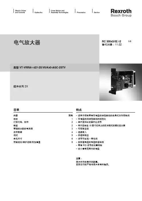
电气放大器类型 VT-VRRA1-527-2X/V0/K40-AGC-2STV组件系列 2XRC 30043/02.12替代对象:11.02目录内容 页码特点1订货代码,附件 2前板2带插脚分配的电路图 3技术数据 4调试 5单元尺寸6项目规划/维护说明/附加信息6特点– 适用于控制带有双增益的特性曲线的先导式方向控制阀– 双增益的阀特性曲线的线性化– 单杆液压缸的面积比调节– 用于安装在 19 英寸机架上的欧洲格式的模拟放大器– 可控输出级– 选通输入– 防短路输出– 调节可能性 – 零位阀– 实际值电缆的电缆断连检测– 带有 PID 调节的位置控制– 较小信号范围内的增益注意:图片所示的是示例配置。
实际交付的产品与图片会有所差异。
1/6订货代码,附件前板首选类型放大器类型材料编号用于带电气位置反馈和弯折的特性曲线的先导式方向控制阀VT-VRRA1-527-20/V0/K40-AGC-2STV08114050684WRL 10...35 V/V1...P-3X...4WRL 10...25 V/V1...P-3X...-750液压组件:用于具有电气反馈的阀 = R阀类型:方向控制阀 = R控制模拟= A选件K40-AGC-2STV = 在40%位置处双增益的先导式方向控制阀客户定制型号 V0 =标准样本型号2X =组件系列 20 至 29(20 至 29:技术数据和插脚分配不变)以下类型的序列号:527 =先导控制阀规格 6单杆液压缸的面积比调节较小信号范围内的增益粗调节精确调节VT-V RR A 15272X V0K40-AGC-2STV配套的板卡插槽:– 开放式板卡插槽 VT 3002-1-2X/32F (请参阅样本 29928)。
仅限用于控制柜安装!0带插脚分配的电路图控制零位控制零位电位计电源启用信号输入错误技术数据(有关这些参数之外的应用,请务必向我们咨询!)在 z2 – b2 处的电源电压 UB 公称电压 24 V =,电池电压 21…40 V,整流后的交流电压 Ueff= 21...28 V(单相,全波整流器)单独在 z2 – b2 处的滤波电容器建议:电容模块 VT 11110(请参阅样本 30750)(只有当 UB的波动值 > 10 % 时方可使用)阀线圈最大值 A/VA 2.7/40(先导控制阀规格 6)最大电流消耗 A 1.7电流消耗可能会随 最小 UB和到控制线圈的极限电缆长度增加功耗(典型值) W37输入信号(控制值)b20:0...±10 Vz20:0...±10 V }差动放大器(Ri= 100 kΩ)信号源b32,z32(10 mA)的电位计 10 kΩ,电源 ±10 V 或外部信号源启用输出级在 z16,U = 8.5...40 V,Ri= 100 kΩ,前板上的 LED(绿色)亮起位置传感器电源b30:–15 Vz30:+15 V先导控制阀实际值信号b22:0...±10 V实际值参考位b24主级实际值信号b26:0...±10 V实际值参考位b28线圈输出b6 – b8 I最大定时电流控制器2.7 A放大器与阀之间的电缆长度线圈电缆: 20 至 20 m 1.5 mm220 至 60 m 2.5 mm2位置传感器: 4 x 0.5 mm2(已屏蔽)主要特点 实际值电缆的电缆断连防护,带有 PID 调节的位置控制,脉冲输出级,具有较短启动时间的快速通电和快速断电,防短路输出,双增益流量特性曲线的线性化调节 零电位通过微调电位计 ±5 % 进行调节,单杆液压缸的面积比调节,较小信号范围内的增益LED 显示 绿色: 启用,黄色: 电缆断连实际值,红色: 欠电压(UB过低)错误消息– 电缆断连实际值– UB 过低– ±15 V 稳定z22:集电极开路输出到 +UB 最大 100 mA;无错误:+UB电路板格式 mm(100 x 160 x 大约 35)/(W x L x H)使用前板为 7 TE 的欧洲格式插入式连接连接器 DIN 41612 – F32环境温度 °C0...+70存储温度范围 °C–20...+70重量 m0.39 kg注意:电源零位 b2 和控制零位 b12 或 b14 或 z28 必须单独通向中心接地(零点)。
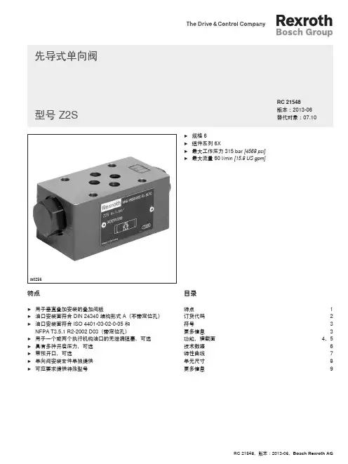
SY1250型履带式液压挖掘机资料 Page 1 of 2 SY1250型履带式液压挖掘机简介 ■ 标准型规格 整机工作重量115,000 kg 铲斗容量(ISO标准)6.8 m3 履带板宽度710 mm ■ 性能 行走速度:低速0~2.5 km/h 高速0~3.2 km/h 回转速度:5.8 rpm 爬坡能力:30゜(60%) 接地比压: 139KPa 铲斗挖掘力(ISO标准):550 kN 斗杆挖掘力(ISO标准):410 kN ■ 发动机 型号:QST19 型式:4冲程水冷、直喷、增压、中冷 进气:涡轮增压进气 气缸数:6 功率:533kW/2100 rpm 最大扭矩:3118 Nm/1500rpm 活塞排量:18.9L 缸径行程:159mm×159mm ■ 液压系统 主泵型式:3泵3回路恒功率变量系统 回转马达(双回转驱动机构):2个轴向柱塞马达 工作泵最大流量:3×495L/ min 回转泵最大流量:1×495L/ min 主安全阀调定压力:31 MPa ■ 油类容量 液压油箱: 800 L 燃油箱:1400 L ■ 技术特点 采用美国原装进口QST19柴油发动机。 液压系统采用力士乐的正控制系统,独立的回转系统, 并使电子控制技术和液压技术的完美结合,可实现多级功率的选择与控制。 可实现液压系统内的合流分流再生等功能,作业效率高。 采用双驱动回转装置,启动制动平稳,使用寿命更长。 先导伺服控制系统,反馈速度快捷,操作灵活自如。 独立的液压油冷却系统,使介质在理想的温度下工作。 自动集中润滑系统,可提高你的工作效率。 SY1250型履带式液压挖掘机资料 Page 2 of 2 采用美国ESCO韧性合金钢的耐磨斗齿。 加强的耐磨型岩石铲斗有着极高的生产率和使用寿命。 多功能仪表盘,使你对机器工作状态了如指掌。 优化设计的驾驶室,使你工作更加舒适愉快。 大功率自动调节冷暖空调,保证有舒适的工作环境。 标准配置燃油加注泵,在工地现场加油更方便、快捷、清洁。 ■ 作业范围 最大挖掘高度(mm) 13000 最大卸载高度(mm) 8450 最大挖掘深度(mm) 7900 最大挖掘半径(mm) 14070
NingBo DeLanBo Hydraulic Power Equipment Co.,Ltd GFT 系列高速壳转减速机GFT series of high speed cranked shell reducer◆概述 IntroductionGFT系列紧凑型高速壳转减速机是传动机构中的理想减速部件。
由于其结构形式特别紧凑,因此这种减速机能应用在安装环境极端困难的地方。
该产品采用先进的设计技术和先进的加工手段,有效地保证了高的承载能力和运行的可靠性。
GFT减速机不仅符合力士乐型系列标准,还可根据具体需要,设计提供与意大利布雷维尼、日本帝人、不二越、KYB、Fairfield 或萨澳相似的替代产品。
由于本公司具有很强的创新设计能力,因此我们可为客户提供咨询服务和合理选型,以期为客户找到最适合的产品解决方案。
根据设计要求,减速机不仅能与力士乐型定量或变量液压马达相连接.如有必要也可以与其它液压马达相匹配。
减速机输入端可根据需要安装弹簧制动、液压释放的多片式停车制动器。
制动器的静制动扭矩与所配液压马达输入扭矩相适应(一般大于1.5倍)。
对于某些减速机还可根据要求安装机械脱开离台器,以便在紧急情况下由其他设备牵引。
防止液压元件被损坏。
该类减速机产品已广泛用于旋挖钻机的主辅卷扬和履带行走驱动.履带起重机的主辅、变幅卷扬和履带驱动、各种钻机履带驱动、压路机、高空作业车轮子驱动、铣刨机和煤矿掘进机的动力头和行走驱动.船舶克令吊、码头和集装箱起重机的驱动机构。
产品不但已在国内三一重工、徐工集团、中联重科等重点用户中使用,并出口到东南亚、印度、韩国、荷兰和俄罗斯等地区及国家。
GFT series of compact high speed cranked shell reducer is a ideal speed reduce part in the rotating mechanism. Due to its compact structure, it could be used in the severely hard installation conditions. The advanced designs as well as the process technology guarantee the high bearing capacity and the operation liability.GFT series speed reducers not only meet the Bosch-Rexroth standards but also could offer the surrogate similar to Brevini, Tejin, Nachi, KYB, Fairfield or Sauer according to the specific demands and design. For we have strong creative style of design capacity, we could provide the customers with the consulting service and suitable type selection to find the optimal products resolution for the clients.As per the design demand, the speed reducers could connect with the Bosch-Rexroth constant and variable hydraulic motors and at the same time could match the other hydraulic motors if necessary. The input end of the reducers could be equipped with spring brake and the multi-plate hydraulic release parking brake according to different needs. The static braking torque of the brake goes with the hydraulic motor’s input torque (generally 1.5 times bigger). According to different needs, some reducers could also be equipped with mechanically falling off clutch to be towed by other equipment under emergency, by which the hydraulic components could avoid being damaged.other products with different installation size and gear ratio. If you need us please don’t hesitate to contact us.This type of reducers has been broadly used for the winches of the rotary drilling rig and also for the band track driving. And they could also apply to the band track hoist, amplitude winches and band track driving, many kinds of band track driving for drilling rig, road roller, wheels driving for aloft work, power head and move driving for the milling machine and the mine tunneling machine and also to the driving facility for shipping cranes, wharf and containers hoist. The products not only have gone to Sany, XCMG and Zoomlion but also have been exported to Southeast Asia, India, Korean, the Netherlands and Russia.◆型号说明SpecificationsGFT XX X X — XX XX — XXX适配液压马达型号 Type of adaptive hydraulic motor减速机总传动比 General rotating ratio of the reducerB表示带停车制动器,无表示不带停车制动器B shows the access of parking brake and vice versa减速机传动级数 Rotating progressionT为履带驱动减速机,W为绞车驱动减速机L为轮子驱动减速机,D为动力头驱动减速机T Band track driving reducer W Winch driving reducerL Wheels driving reducer D Power head driving reducer减速机最大输出扭矩(kN·m)Maximum output torque of the reducer (KN.m) Ningbo de lan bo hi gh speed hydraulic cranked shell reducer ◆型号举例 Speci fi cation exampleGFT60T3-B86-A2FE80/61WVZL10表示该减速机最大输出扭矩为60KN·m,用于行走驱动,采用三级行星减速,带停车制动器,总传动比为86,所配液压马达型号为A2FE80/61WVZL10。
A轴向柱塞单元
名称型号编号版本
第二册目录|行走机械液压 1/2
⑤定量马达
A2FM轴向柱塞定量马达
A2FE插装式定量马达
定量马达A4FM
定量马达A10FM A10FE
⑥变量马达
轴向柱塞变量马达A6VM
A6VE变量插装式马达
双排量马达A10VM、插装式
⑦常规要求及备件
矿物油基液压油液
用于轴向活塞件元件的环保型液压
RC 91001
RC 91008
RC 91120
RC 91172
RC 91604
RC 91606
RC 91703
RC 90220
RC 90221
A2FM
A2FE
A4FM
A10FM/E
A6VM
A6VE
A10VM/E
07.05
04.05
04.00
06.06
05.06
06.05
06.04
05.03
01.02
油HEES、HEPG和HETG
使用HF油液的轴向柱塞元件万向轴连接法兰
吸油管
冲洗与补油阀SV
功率阀LA
BVD平衡阀
通用通轴驱动
RC 90223
RC 95001
RC 95004
RC 95512
RC 95514
RC 95522
RC 95581
11.99
11.00
02.97
12.98
09.99
05.03
12.05 SV
LA
BVD
für A4VS
A10VE
A 轴向柱塞单元
名称 型号 编号 版本
⑧ 外啮合齿轮元件
⑨ 径向柱塞马达
⑩ 减速机
2/2 行走机械液压 | 第二册目录
外啮合齿轮泵F 型外啮合齿轮泵静音型外啮合齿轮马达液压马达(径向柱塞元件,多行程)径向柱塞马达(多行程)MCR 5型液压马达(径向柱塞元件,多行程)液压马达(径向柱塞元件,多行程)液压马达(径向柱塞元件,多行程)紧凑型静液压传动装置HYDROTRAC
GFT 用于定量或变量马达
紧凑型静液压传动装置HYDROTRAC 带内置液压双速马达A10VT 回速减速机MOBILEX
回转驱动MOBILEX GFB 带斜盘马达A10FD
回转驱动MOBILEX GFB 适用于变桨和偏航调节
卷扬减速机MOBILEX GFT-W 行星减速机REDULUS
RC 10089RC 10095RC 14026
RC 15205RC 15206RC 15207RC 15208RC 15209
RC 77110RC 77111RC 77201RC 77204RC 76111RC 77502RC 76120
AZPF AZPS
AZMF, AZMN, AZMG
MCR03MCR05MCR10MCR15MCR20
GFT GFT 7-40GFB GFB GFB GFT-W GMH/GME
08.0405.0401.05
02.9806.0602.9810.9403.95
07.0407.0405.0603.0109.0405.0410.05。