在重庆地区古生界页岩裂缝发育南中国第二部分构造应力场数值模拟与裂缝分布预测
- 格式:pdf
- 大小:4.44 MB
- 文档页数:13


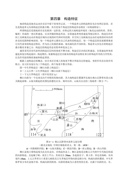
川东北马路背须四段储层裂缝预测刘聪颖;梅梓;陶佳丽;刘志毅;蔺明阳;罗梦原【摘要】根据马路背须四段现今构造特征,建立起该地区的地质模型,利用数值分析技术,模拟计算马路背须四段气藏岩体的古构造应力场和破裂接近程度系数(η),结合岩石力学与构造地质学理论、野外裂缝观测结果以及实际生产资料,对马路背须四段裂缝发育程度、裂缝类型及产状进行综合预测,确立马路背翼部高陡带、背斜长轴及断裂带为裂缝的分布发育带,为下一步勘探部署提供依据.【期刊名称】《重庆科技学院学报(自然科学版)》【年(卷),期】2014(016)001【总页数】4页(P85-88)【关键词】马路背;须四段;构造应力场;裂缝;预测【作者】刘聪颖;梅梓;陶佳丽;刘志毅;蔺明阳;罗梦原【作者单位】西南石油大学资源与环境学院,成都610500;西南石油大学资源与环境学院,成都610500;西南石油大学资源与环境学院,成都610500;西南石油大学资源与环境学院,成都610500;长庆油田公司采油三厂,银川750000;西南油气田分公司川中油气矿,四川遂宁629000【正文语种】中文【中图分类】TE122.2+21 地质概况1.1 构造及地质特征马路背位于通南巴构造带涪阳坝次级构造上(图1),通南巴构造带位于四川盆地东北缘,米仓山冲断构造带位于其北侧,东北侧为大巴山前缘弧形推覆构造带,南邻川中平缓构造带,北西与米仓山前缘凹陷带相接,东南与通江凹陷带相连,是古生代—早中三叠世四川盆地地台沉积的一部分,也是中生代和新生代米仓山—大巴山的前陆盆地[1]。
图1 马路背构造位置图马路背构造须家河组四段底界由马1断鼻和马2断背斜组成,主要存在北东向和北西向2组断层,它们是多期构造运动的结果。
马路背构造上三叠统须家河组主要发育湖相与河沼相的陆相碎屑岩,可划分为须五段、须四段、须三段、须二段及须一段共5个岩性段[2-3]。
须四段上部为杂色、深灰色砾状砂岩;中部黑色泥岩、灰色中砂岩互层,下部灰色含砾粗砂岩与须三段上部黑色页岩及黑色泥岩呈整合接触。
第四章构造特征地质构造是地壳运动在岩层中留下的变形记录。
一个构造单元的构造特征包含有两层意思,首先是构造单元内部构造层的叠合数,其次是每个构造层的构造形态特征(结构面特征)。
所谓构造层是指地质历史发展到一定阶段、在特定的大地构造环境里(地壳运动的性质、类型、幅度)形成的一套沉积建造,以及伴随的构造形态、岩浆建造和变质建造等地层组合。
构造层在时间上反映地壳运动在构造区域内出现的时代和时间范围,在空间上反映地壳运动在延续的时间内所涉及的范围和影响深度。
每一个构造单元都有自己代表性的构造层。
每一个构造层的发展都要继承它历代前身的构造层特征,作为自己发展的基础。
地壳演化的不同阶段、构造单元内包含的构造层叠合数有多寡之分,构造层的构造形态有简单和复杂之分。
通常采用具有代表性的构造层层间的角度不整合面、构造层层内的沉积建造、岩浆建造和变质建造来划分构造旋回、构造期次;依据构造层层内展布的构造形态特征来分析构造作用的力学性质,以及作用前的物质基础和构造背景。
根据上述构造层的概念,结合本区区域上的角度不整合界面及沉积建造、变质作用及岩浆作用特点,实习区内划分为三个构造层、两个角度不整合界面。
Ⅲ—中生界构造层(柳江向斜上构造层)Ⅱ—上元古界—古生界构造层(柳江向斜下构造层)Ⅰ—下元古界构造层(绥中花岗岩γ2)柳江向斜为一个近南北向不对称的短轴向斜。
其大地构造位置属华北地台燕山沉降带东段山海关隆起南缘。
山海关隆起的范围包括遵化以东、锦州以西、山海关以北的三角地带(图2—7)。
图4—1 燕山沉降带内部单元划分图(据北京地院中国区域地质讲义,第一册,1959)A—兴隆朝阳凹陷;B—山海关隆起;C—蓟县凹陷;D—密云隆起;E—西山凹陷柳江盆地主要构造线为北北东走向。
在构造形态上,柳江盆地是由晚元古代到中生代地层组成的向斜构造,北起城子峪,南至上平山,其南北长20km;东起张岩子、黄土营,西达花场峪,东西宽约10km。
上元古界青白口系景儿峪组及古生界地层环绕向斜边缘分布,构成向斜的翼部。

第23卷第2期重庆科技学院学报(自然科学版)2021年4月人工裂缝对深层页岩气藏稳产能力的影响丁洋洋向祖平敖翔李志强杨威王子怡程泽华雷函林(重庆科技学院石油与天然气工程学院,重庆401331)摘要:为了定量分析人工裂缝参数对深层页岩气藏稳产能力的影响,针对深层页岩气藏进行渗流数值模拟研究。
基于渗流力学理论,建立了考虑人工裂缝导流能力、人工裂缝高度和人工裂缝半长等主要影响参数的数值模型&对渝西地区深层页岩气藏的稳产能力和产气量进行了预测'预测结果显示,稳产时间和累计产气量均随着这3个参数的增大而得以优化,但累计产气量的增幅逐渐减小,前中期稳产能力的改善效果最显著。
研究认为,在深层页岩气储层压裂改造中&应对裂缝参数进行模拟优选,以适当增加压裂段数,并尽可能地提高人工裂缝的导流能力、加大裂缝半长,从而达到最佳压裂改造效果和较高稳产能力。
关键词:深层页岩气藏;数值模型;人工裂缝;稳产能力中图分类号:TE371文献标识码:A文章编号:1673-1980(2021)02-0006-06相关统计数据显示&我国的页岩气可采储量大约有3*x1012h3,占全球页岩气可采储量的22%左右,开发潜力巨大[%-3]。
随着油气勘探的不断推进,中浅层油气资源的开发已较为成熟⑷,而深层油气资源的开发有待深入研究[5-6]o我国的页岩气有*5%以上是埋深超过3500h的深层页岩气[7-9]o 近年来,在普光、威远-荣县、东溪等深层大型气田取得了深层一超深层页岩气勘探开发新突破[10-%%],深层页岩气也逐渐成为我国页岩气勘探开发的主要接替领域[12]o在页岩气的水平井开采过程中,往往需要针对页岩储层实施大规模压裂改造[%3];然而,深层页岩气应力系数差异普遍较大,压裂后多形成单条人工裂缝,且随着支撑剂嵌入和流体压力下降裂缝很快失效[14-%6]o这极大地影响了深层页岩气井产气能力和稳产能力。
关于页岩气压裂裂缝参数对页岩气藏产能的影响&现有研究大多只作了定性分析,而鲜有定量解释。

四川长宁地区页岩储层天然裂缝发育特征及研究意义-天津地质调查中⼼第39卷第2期地质调查与研究Vol.39No.22016年06⽉GEOLOGICAL SURVEY AND RESEARCHJun.2016四川长宁地区页岩储层天然裂缝发育特征及研究意义朱利锋1,翁剑桥2,3,吕⽂雅4(1.⼭西省地质调查院,太原030006;2.页岩⽓评价与开采四川省重点实验室,成都610091;3.四川省煤⽥地质局,成都610072;4.中国⽯油⼤学(北京)地球科学学院,北京102249)摘要:页岩⽓是⾮常规天然⽓的⼀种,具有极低的孔隙度和基质渗透率,在勘探开发过程中势必要进⾏天然裂缝研究和评价。
通过对长宁地区⼤量野外露头及岩⼼的观测统计,采⽤了页岩天然裂缝的地质成因、⼒学性质和形态特征相结合的页岩裂缝分类⽅案,将该区天然裂缝划分为构造裂缝、成岩裂缝和异常⾼压裂缝三类,其中构造裂缝进⼀步依据形态及⼒学性质划分为穿层剪切缝、层内扩张缝和顺层滑脱缝;成岩裂缝进⼀步依据形态特征划分为层理缝和收缩缝。
本⽂论述了分类⽅案的合理性,并分别阐述了页岩中各天然裂缝类型的特征。
在此基础上,总结了页岩天然裂缝研究对页岩⽓勘探开发的作⽤及意义。
层内扩张缝和页理缝影响页岩⽓的富集,⽽穿层剪切缝和顺层滑脱缝则在不同地质背景中影响页岩⽓的保存。
关键字:页岩⽓;天然裂缝;类型;富集规律;四川长宁地区中图分类号:P624⽂献标识码:A⽂章编号:1672-4135(2016)02-0104-07收稿⽇期:2016-03-16资助项⽬:国家重点基础研究发展计划(973)项⽬“中国南⽅海相页岩⽓⾼效开发的基础研究(2013CB228000)"作者简介:朱利锋(1986-),男,助理⼯程师,硕⼠研究⽣,2013年毕业于中国⽯油⼤学(北京)构造地质学专业,现主要从事地质矿产相关⼯作,Email:zzff2012@/doc/1b5e008132d4b14e852458fb770bf78a64293a7b.html 。

川西坳陷孝泉-新场地区须家河组二-四段构造应力场模拟及裂缝发育区带预测张守仁;万天丰;陈建平【期刊名称】《石油与天然气地质》【年(卷),期】2004(025)001【摘要】弹-塑性增量法应力场模拟,就是用若干个直线段去逼近抛物线型应力-应变曲线,在每个直线段中按有限元法进行弹性模拟计算.运用该方法对孝泉-新场地区须家河组二-四段构造应力场进行了精细数值模拟.结果显示孝泉-新场地区为一构造裂缝不发育地区,仅断裂带附近区域构造裂缝较发育.经地震剖面解释及构造演化分析,该区主要断裂带是油气运移的良好通道,且不存在油气的严重漏失.因此,断裂带附近区域是天然气勘探最有利区域,特别是近东西向断裂与现今主应力方向平行,表现为开启性,对天然气的导通作用更为明显.【总页数】6页(P70-74,80)【作者】张守仁;万天丰;陈建平【作者单位】中国地质大学地球科学与资源学院,北京,100083;中国地质大学地球科学与资源学院,北京,100083;辽宁工程技术大学资源环境学院,辽宁阜新,123000【正文语种】中文【中图分类】TE122.1【相关文献】1.川西孝泉-新场地区须家河组四段裂缝分布特征 [J], 张克银2.川西坳陷孝泉-新场地区须家河组四段储层控制因素及预测地质模型 [J], 孟万斌;吕正祥;刘家铎;田景春;冯明石;李敏3.川西坳陷须家河组致密砂岩储层裂缝发育特征及其成因——以孝泉—新场—合兴场地区为例 [J], 王春梅;黄思静;孙治雷;胡作维;黄可可;佟宏鹏4.四川盆地川西坳陷新场须家河组二段致密砂岩储层裂缝发育特征及主控因素 [J], 李王鹏;刘忠群;胡宗全;金武军;李朋威;刘君龙;徐士林;马安来5."断缝体"概念、地质模式及其在裂缝预测中的应用——以四川盆地川西坳陷新场地区须家河组二段致密砂岩气藏为例 [J], 刘振峰;刘忠群;郭元岭;季玉新;李王鹏;林恬;陈天胜;金武军因版权原因,仅展示原文概要,查看原文内容请购买。
第 51 卷 第 6 期石 油 钻 探 技 术Vol. 51 No.6 2023 年 11 月PETROLEUM DRILLING TECHNIQUES Nov., 2023◄油气开发►doi:10.11911/syztjs.2023095引用格式:舒红林,刘臣,李志强,等. 昭通浅层页岩气压裂复杂裂缝扩展数值模拟研究[J]. 石油钻探技术,2023, 51(6):77-84.SHU Honglin, LIU Chen, LI Zhiqiang, et al. Numerical simulation of complex fracture propagation in shallow shale gas fracturing in Zhaotong [J].Petroleum Drilling Techniques,2023, 51(6):77-84.昭通浅层页岩气压裂复杂裂缝扩展数值模拟研究舒红林1, 刘 臣1, 李志强2, 段贵府3, 赖建林1, 江 铭1(1. 中国石油浙江油田分公司,浙江杭州 310023;2. 重庆科技学院石油与天然气工程学院, 重庆 401331;3. 中国石油勘探开发研究院, 北京100083)摘 要: 昭通浅层页岩气田主体埋深在1 000~2 200 m,地层压力系数低,效益开发难度较大,水力压裂是唯一增产措施,但目前国内尚无对中浅层页岩储层实施规模开发的经验可供借鉴,水力压裂工艺参数仍有优化空间。
为明确目标昭通浅层页岩气田裂缝扩展主控影响因素,优化页岩气水平井压裂参数,针对该页岩气田储层天然裂缝发育、水平应力差小,主体改造工艺射孔簇较多等地质、工程特点,开展了昭通浅层页岩气压裂复杂裂缝扩展数值模拟研究。
采用位移不连续法,考虑天然裂缝和水力裂缝的相互作用模式,基于压裂裂缝流动方程、裂缝宽度方程和物质平衡方程,推导了复杂裂缝扩展数学模型;针对昭通浅层页岩气实际地质特点,基于建立的数学模型优化了施工参数,明确了天然裂缝内聚力、射孔簇数是影响改造体积的主要因素。
天 然 气 工 业Natural Gas Industry 第41卷第5期2021年5月· 42 ·四川盆地西南缘山地复杂构造区页岩气富集模式及勘探启示:一个页岩气新区杨平1,2 余谦1,2 牟传龙1,2 汪正江1,2 刘伟1,2赵瞻1,2 刘家洪1,2 熊国庆1,2 邓奇1,21.中国地质调查局成都地质调查中心2.自然资源部沉积盆地与油气资源重点实验室摘要:四川盆地南部页岩气是目前中国海相页岩气勘探开发最为成功的地区,为了进一步开拓页岩气的新战场,寻找新的页岩气储量、产量接替区块,需要不断丰富、完善和建立不同构造背景下的页岩气评层选区标准。
前期的勘探实践表明,四川盆地西南缘山地复杂构造区页岩含气性差异大,系统研究分析该区页岩气富集规律对于寻找页岩气勘探新区具有重要的意义。
为此,基于四川盆地西南缘山地复杂构造区5口井的实钻资料,在对龙马溪组页岩露头和岩心、岩屑有机地球化学、物性、含气量、生烃史和孔隙演化史开展系统实验和分析的基础上,探讨了页岩含气性的主要控制因素和页岩富集模式,为一个页岩气新区的诞生奠定了坚实的地质基础。
研究结果表明:①四川盆地西南缘山地复杂构造区龙一段1亚段页岩平均TOC为3.02 %~4.97 %,R o为2.38 %~3.37%,局部富集区平均总含气量可达4.62 m3/t,属于优质页岩;②生烃史研究表明,页岩具有“慢热低熟”特征,生烃时间晚,热演化速率慢,现今成熟低,晚期扩散时间短,为页岩气的富集创造了有利条件;③孔隙演化史揭示页岩孔隙演化可以划分为孔隙锐减、孔隙减少、有机孔形成、孔隙保存、有机孔消亡和岩溶作用等6个演化阶段,有机质孔及有机碳含量是页岩含气量最直接的控制因素;④有利陆棚沉积相带利于形成规模储集空间和有效孔隙,不同构造样式和构造部位保存条件的差异性控制了不同孔隙演化阶段,山地复杂构造区页岩气具有水平分带、差异富集的特点,“慢热低熟”和“构造缓抬”有利于页岩气的长期富集与保存。
微电阻率成像测井在识别页岩岩相与裂缝中的应用黄振华;程礼军;刘俊峰;谢庆明;王飞【摘要】页岩气储层微电阻率成像测井的应用与研究,目前国内还处于起步阶段。
与常规储层相比,页岩气储层岩性更加复杂,矿物类型较多,裂缝识别难度大。
通过对渝东南地区Q1井微电阻率成像测井资料的精细标定与分析,结合页岩气储层8块岩心薄片、37块岩心矿物成分,总结常规测井曲线特征,引入图版形式准确区分出该地区4种页岩岩相识别模式。
在此基础上选取有利岩相,自动拾取裂缝并定量计算了该井裂缝孔隙度等参数,确定该井最大主应力近东西方向,提高了页岩气勘探开发效率,为后期压裂改造提供了可靠依据。
%The application and study of micro-resistivity image logging to the shale gas reservoir are inthe initial stage. Compared with conventional reservoir, the lithology of shale gas reservoir is more complicated, the mineral type is more, the fracture identification is harder. By fine calibrating and analyzing themicro-resistivity image logs, combining with 8 core-slices and of mineral composition 37 cores of well Q1 shale gas reservoir in the southeast of Chongqing, summarizing conventional well logs, we can explore 4 recognition modes of shale facies with plate. Selectting favorable shale facies on this basis, auto-picking up and quantitative evaluating fracturesin the area, can improve the efficiency of exploration and development, provide reliable basis to fracturing.【期刊名称】《煤田地质与勘探》【年(卷),期】2015(000)006【总页数】4页(P121-123,127)【关键词】微电阻率成像测井;页岩岩相;矿物组分;裂缝【作者】黄振华;程礼军;刘俊峰;谢庆明;王飞【作者单位】国土资源部页岩气资源勘查重点实验室,重庆地质矿产研究院,重庆400042;国土资源部页岩气资源勘查重点实验室,重庆地质矿产研究院,重庆400042;国土资源部页岩气资源勘查重点实验室,重庆地质矿产研究院,重庆400042;国土资源部页岩气资源勘查重点实验室,重庆地质矿产研究院,重庆400042;国土资源部页岩气资源勘查重点实验室,重庆地质矿产研究院,重庆400042【正文语种】中文【中图分类】P631渝东南地区地层抬升较高、构造挤压强烈、褶皱发育,区内背、向斜构造平行排列,褶皱轴部走向大致呈北东–南西向延伸(30°~45°),两翼倾角陡倾且基本对称是扬子板块剥蚀区的典型代表。
Fracture development in Paleozoic shale of Chongqing area (South China).Part two:Numerical simulation of tectonic stress field and prediction of fracturesdistributionWeite Zeng a ,b ,c ,Wenlong Ding a ,b ,c ,⇑,Jinchuan Zhang a ,b ,c ,Yeqian Zhang a ,b ,c ,Ling Guo d ,Kai Jiu a ,b ,c ,Yifan Li a ,b ,caSchool of Energy Resources,China University of Geosciences,Beijing 100083,ChinabKey Laboratory for Marine Reservoir Evolution and Hydrocarbon Abundance Mechanism,Ministry of Education,China University of Geosciences,Beijing 100083,China cKey Laboratory for Shale Gas Exploration and Assessment,Ministry of Land and Resources,China University of Geosciences,Beijing 100083,China dDepartment of Geology,Northwest University,Xi’an 710069,Chinaa r t i c l e i n f o Article history:Available online 19July 2013Keywords:Longmaxi ShaleMechanical rock properties Tectonic stress field Fractures distribution Southeast Chongqinga b s t r a c tA tectonics sedimentation evolution has been researched in Southeast Chongqing,and the reasonable Longmaxi shale highstand system tract (HST)and transgressive system tract (TST)geological model were built respectively based on the rock mechanical test and acoustic emission experiment which the sam-ples are from field outcrop and the Yuye-1well.The Longmaxi shale two-dimension tectonic stress field during the Cenozoic was simulated by the finite element method,and the distribution of fractures was predicted.The research results show that the tectonic stress field and the distribution of fractures were controlled by lithology and structure.As a result of Cretaceous movement,there are trough-like folds (wide spaced synclines),battlement-like folds (similar spaces between synclines and anticlines)and ejec-tive folds (wide spaced anticlines),which are regularly distributed from southeast to northwest in the study area.Since the strain rate and other physical factors such as the viscosity are not taken into account,and the stress intensity is the main factor that determines the tectonic strength.Therefore,the stronger tectonic strength leads the higher stress intensity in the eastern and southeastern study area than in the northwest.The fracture zones are mainly concentrated in the fold axis,transition locations of faults and folds,the regions where are adjacent to faults.The fragile mineral contents (such as siliceous rock,carbonate rock and feldspar)in the shelf facies shale from south of the study area are higher than in the bathyal facies and abyssal facies shale from center of the study area.The shales characterized by low Poisson’s ratio and high elastic modulus from south of the study area are easily broken during Cenozoic orogenic movement.Ó2013Elsevier Ltd.All rights reserved.0.IntroductionThe southeastern portion of Chongqing is the pilot experimen-tal area in China for the key strategic investigations of shale gas.In 2009,the Yuye-1well,which was the first Chinese well for the strategic investigation of shale gas,was drilled in this experimen-tal area.By 2011,the Yuke-1,Youke-1,Pengye-1,and Qianye-1wells had been successively drilled in this area.These five wells revealed the existence of two formations of high-quality shale in the region in question,namely,the Lower Silurian Longmaxi Shale and the Lower Cambrian Niutitang Shale.In particular,amaximum total hydrocarbon concentration of 22.50%has been reached by the Pengye-1well,which targets a shale layer in the Lower Silurian Longmaxi-Upper Ordovician Wufeng Shale,and the greatest desorption gas content of this field was 2.30m 3/t.Moreover,for the Qianye-1well,which also targets a shale layer of this formation,after hydraulic fracturing treatment and drain-age tests,a wellhead pressure of 3MPa was achieved,and the instantaneous flow rate for the initial shale gas test was 308m 3/h;this rate is sufficient for industrial gas operations.In recent years,various studies have been conducted to address shale gas exploration in the marine shale of North America.Most of these studies on shale gas exploitation have focused on identifying the most effective approaches for fracturing shale;in fact,fractures are a critical determinant of the success of shale gas wells (Hill and Nelson,2000;Curtis,2002;Warlick,2006;Gale et al.,2007;Li et al.,2007,2009;Nie et al.,2009a;1367-9120/$-see front matter Ó2013Elsevier Ltd.All rights reserved./10.1016/j.jseaes.2013.07.015⇑Corresponding author at:School of Energy Resources,China University ofGeosciences,Beijing 100083,China.Tel.:+861082320629;fax:+861082326850.E-mail address:dingwenlong2006@ (W.Ding).Tan,2009).Organic-rich shale with low porosity and permeability can form effective natural gas reservoirs if this shale has devel-oped sufficient natural fractures,microfractures,and nanometer-scale pores and fractures within rocks(Sun et al.,2008)or if frac-turing treatments can generate a fracture system that features a large number of fractures.The development of natural fracture systems not only directly affects the mining efficiency of shale gas reservoirs but also determines the quality and production lev-els of these reservoirs(Montgomery et al.,2005;Bowker,2007; Zhang et al.,2003).Higher levels of fracture development increase the total gas content of a shale formation by both enlarging the volume of unbound natural gas that is contained in this formation and promoting the desorption of adsorbed natural gas from the shale(Curtis,2002;Nie et al.,2009b;Zhang et al.,2003,2004; Chen et al.,2009).Based on a detailed analysis of the tectonic and sedimentary evolution in southeastern Chongqing area that combines investigations of rock mechanics and acoustic emis-sions experiments,this study applies thefinite element method to simulate the two-dimensional tectonic stressfield that existed during the development of the fracture in Cenozoic for the Lower Silurian Longmaxi Shale of the study region.This approach al-lowed fracture distributions in this shale to be predicted.These fracture distribution predictions can provide an important theo-include many types of faults,which are mainly inclined to the northwest and southwest(Zhang et al.,2010).As a result of the subduction of the Pacific plate under the Asian plate in the Creta-ceous,the compressive strain transfers and the energy decays in the SE–NW direction sequentially produced Jura-type te in the Cretaceous movement,the direction of regional stress twisted in a counterclockwise direction,altering the morphology of the existing fold structure by causing S-shaped or arc-like folds to form in the axial plane.The tectonic stresses of folds formed in the Cretaceous underwent relaxation or release in the Cenozoic, leading to the creation of a series of large-scale NNE-trending nor-mal faults along anticlinal axes and wings that consisted of horst and graben fault systems;these processes ultimately created the modern tectonic landscape of the study area(see Figs.1and2).The graptolite Longmaxi Shale in southeastern Chongqing(i.e., the lower strata of the Longmaxi Formation)was created during a brief large-scale transgression that occurred early in the Silurian and provided important hydrocarbon source rocks of the Yangtze plate,particularly in the Sichuan Basin and its surrounding regions (Wo et al.,2007;Zhang et al.,1987).There is a lack of applicable logging data and seismic data in the research area;therefore, cross-sectional analyses of local outcrops and core facies of the Yuye-1well were parative assessments of theFig.1.Tectonic map of Southeast Chongqing area.268W.Zeng et al./Journal of Asian Earth Sciences75(2013)267–279Fig.2.Tectonic cross-section of southeastern Chongqing area.Fig.3.Paleo-geographic reconstruction of the transgressive system tract(TST)for the Longmaxi Shale. Fig.4.Paleo-geographic reconstruction of the highstand system tract(HST)for the Longmaxi Shale.were deposited in this region were black carbonaceous shale,dark gray shale,dark gray silty shale,and siliceous shale.The northeast region of the study area was likely affected by the‘Hunan-Hubei Underwater Plateau’(Fan et al.,2012;Chen et al.,2004),and there-fore largely featured a shallow-water shelf sedimentary environ-ment.The major rock types that were deposited in this region were gray shale,black shale,and calcareous shale.The south region of the study area was mostly a shallow-water shelf during the TST, although portions of this region consisted of sandy shelf.The rock types that were deposited in this region were primarily gray silty mudstone,calcareous shale,and gray siltstone.The HST featured lower sea levels than the TST;therefore,shale deposition occurred in shallower water during the HST than during the TST.During the HST,the subsidence center was located in the northern and north-western portions of the research area,and sediments primarily came from the south.In the southern portion of the study region, the area of sandy sediments increased during the HST,and sandy shelf depositions primarily occurred at this time;the major rock types that were deposited in this region were calcareous shale, gray argillaceous siltstone,and light gray siltstone.During the HST,the north-central region of the study area is represented by deep-water shelf and bathyal deposits,but the extend of these types of deposits decreased significantly during the HST relative to the TST.The main rock types deposited in this region were black carbonaceous shale,dark gray shale,and gray argillaceous silt-stone.The scope of the shallow-water shelf depositional area in the examined region increased in the HST compared with the TST,and the primary rock types deposited in this area were calcar-eous shale and silty shale.2.Methods for tectonic stressfield simulation and fracture distribution prediction2.1.Tectonic stressfield simulationThe tectonic stressfield typically refers to the crustal stressfield that causes tectonic movements.The purpose of tectonic stress field simulation is to model the distribution of stress inside a rock block through the application of boundary forces,usingfirst inver-sion and forward modeling approaches(Ye,2011;Li,2010;Liu, 2009).In this study,thefinite element method and ANSYS com-puter software were employed to produce a two-dimensional sim-ulation of the stressfield of the Longmaxi ShaleChongqing area.The simulation of a tectonic stressfieldsteps:(1)the establishment of a geological model;lishment of a mechanical model;(3)theematical model;and(4)computer calculations andsimulation results.2.1.1.Establishment of a geological modelThe geological model considers petrographyThefinite geometry of active structure will becessive tectonic stressfields during multipletory constitutes a comprehensive picture of thetectonic stressfields over time.However,thefected by the most recent tectonic stressfield(inthe Cenozoic movement).In the absence of seismicin the study region,the targeted layers to berated from their surrounding rock block based notture and the historical sedimentary evolution ofbut also on the outcrop data and drilling core dataThis approach allowed for the establishment ofgeological models of the TST and HST for thethe Cenozoic(Figs.3and4).2.1.2.Establishment of a mechanical modelThe establishment of a mechanical model includes the follow-ing tasks:(1)to determine the loading regime for geological bodies and constraints on types and methods of geological loading(i.e., determine the boundary conditions);(2)to determine the mechan-ical parameters for different rock units of the studied layers;and (3)to determine the mechanical parameters for faults and folds, which will directly affect the simulation results.(1)Determination of the loading regime for geological bodiesand constraints on the types and methods of geological load-ing(i.e.,the determination of the boundary conditions).To begin with examinations of macroscopic effects,geological bodies were assumed to be homogeneous blocks or slices of rock bodies and were simulated as pieces of uniformly elastic material. The boundary conditions included displacement boundary condi-tions and stress boundary conditions.It was assumed that the force on a boundary is a set of determined values and that this force is uniformly distributed across the boundary of interest.The acoustic emission experiments on rock samples were performed at the Geo-stress Measurement Laboratory of the Chinese Institute of Geome-chanics.In particular,the experimental setup utilized a4010 Acoustic Emission instrument,a300kN universal press,strain sen-sors,and a computer(Figs.5and6).This device can assess stresses from paleostress periods and reveal the maximum effective paleo-stress that have been experienced by the examined strata(Ding and Shao,2001).This study focused on measuring the maximum principal stress r1of Longmaxi Shale from the Yuye-1well during tectonic movements of different periods(Table1).The experimen-tal samples were obtained from the Yuye-1well;in particular,15 standard25mmÂ50mm cylindrical samples were acquired by drilling in the core column,perpendicularly to the bedding plane of core.The most intense tectonic movement in the research area was the Cretaceous movement,followed by the Cenozoic movement. Therefore,it is reasonable to believe that the maximum tectonic stress that was experienced by the Longmaxi Shale of the Yuye-1 well would have been148.8MPa in the Cretaceous and 122.5MPa in the Cenozoic.During the Cenozoic,the research area as a whole experienced a compressional stressfield in the north-west–southeast direction.Given that the Yuye-1well is located on the axis of the Guochangba anticline of the city of Lianhu,it5.Curve of paleostress measurements based on initial pressures of acoustic emissions for shale samples from the Yuye-1well.270W.Zeng et al./Journal of Asian Earth Sciences75(2013)267–279applied to the upper right and lower left boundary;constraints were placed on displacement in the X and Y directions for the nodes at the right corner and the left corner of the model,allowing all other units to move freely;and a set of25MPa pull tensions were applied in parallel in the direction of maximum principal stress at the nodes of the upper left and the lower right corner to simulate the sinistral shear stress that was experienced in the Cenozoic(Fig.7).(2)Determination of mechanical parameters for various rockunits of the studied layers.The geological model of this study divided the examined units into the following major unit types(Table2):fault zones,fold zones,and zones of ordinary sedimentary strata.Based on fault size,fault zones were subclassified intofirst-order,second-order, and third-order faults.The onlyfirst-order fault in the research area is the Qiyao Mountain basement fault,and other faults in the region were divided into second-order and third-order faults based on morphological scale and extension range.Fold zones, which have been produced by southeast-northwest energy trans-fers and energy decays,were divided into trough-like folds(wide spaced synclines),battlement-like folds(similar spaces between synclines and anticlines)and ejective folds(wide spaced anti-clines).Lithological differences were utilized to subdivide the examined sedimentary layers into various unit types,including carbonaceous shale,siliceous shale,black shale,calcareous shale, and argillaceous siltstone.Because this study primarily seeks to provide two-dimensional simulations of tectonic stressfields,the major mechanical param-eters of rocks that are required are the elastic modulus and Pois-son’s ratio.Experiments to examine rock mechanics were performed in the Rock Mechanics Testing Laboratory of the Univer-sity of Science and Technology Beijing.In particular,these experi-ments used not only a uniaxial rock mechanical testing platform that consisted of a WGE-600universal testing machine,100-ton pressure sensors,7V14program-controlled recorder,and an E4800computer but also used a triaxial rock mechanical testing platform that consisted of a TYS-500triaxial rock testing machine,100-ton pressure sensors,a7V14program-controlled recorder,and an E4800computer.The experiment was performed in accordance with the protocols specified by Chinese standard SL264-2001,‘‘Specifications for Rock Tests in Water Conservancy and Hydro-electric Engineering’’.In accordance with the burial depth of the Longmaxi Shale in the study area and the actual number of sam-ples that were examined,the confining pressures that were uti-lized in the triaxial rock mechanics experiments were0,5,10, and15MPa,and the influence of ground temperature was not con-sidered.The uniaxial rock mechanics experiment was primarily de-signed to measure the parameters of rock density,uniaxial compressive strength,elastic modulus,Poisson’s ratio,and tensile strength,although other parameters were also examined.In the triaxial rock mechanics experiment,measurements of axial rupture stress,elastic modulus,and Poisson’s ratio of samples at different confining pressures were used to calculate cohesion and internal friction angle,and other shear strength parameters(Table2).The Longmaxi Shale samples for rock mechanics measurements were collected from the Yuye-1well and outcrops in thefield.In partic-ular,for each examined lithology,the samples were obtained by drilling vertically to the bedding plane;these samples were then processed into19standard25mmÂ50mm cylindrical samples for each examined lithology.(3)Determination of mechanical parameters for faults andfolds.In this study,to address fault zones and fold zones(Table3), fault zones were defined as‘weak zones’.The elastic modulus of a fault zone is typically smaller than the elastic modulus of a nor-mal stratum;in particular,this modulus is generally50–70%of the modulus of a corresponding normal stratum.The Poisson’s ratio of a fault zone is larger than the Poisson’s ratio of a corresponding normal sedimentary rock stratum,and the difference between these two ratios is typically between0.02and0.1.Fold zones are defined as‘‘hard zones’’.The elastic modulus of a fold zone is typ-ically larger than the elastic modulus of a normal stratum;in par-ticular,this modulus is generally150–300%of the elastic modulus of a corresponding normal stratum.The Poisson’s ratio of a fold zone is smaller than the Poisson’s ratio of a corresponding normal sedimentary rock stratum,and the difference between these two ratios is typically between0.01and0.15.6.Curve of paleostress measurements based on repeated pressures of acoustic emissions for shale samples from the Yuye-1well.Table1results of tectonic stress measurements from acoustic emissions for shale samples from the Yuye-1well.Well#Depth(m)Formation Effective tectonicstress r1duringvarious periods(MPa)Major stages ofknown tectonicmovement(episode)Yuye-10–325.5Longmaxi23.1,40.8,57.4,91.0,122.5,148.86Mechanical model of the Longmaxi Shale in southeast Chongqing during Cenozoic.2.1.3.Establishment of the mathematical modelA geological model was constructed in the form of a triangular mesh that was subdivided into a series of node and element grids. The geological model of the HST strata included9965nodes and 19,670elements,whereas the geological model of the TST strata included8270nodes and16,330elements.After the model bound-ary conditions and the applied load had been determined,thefinite element method was applied to solve the model.The fundamental notion underlying thefinite element method involves dividing the domain of a continuousfield function that must be solved into a series of elements that are only connected at nodes,allowing for an unknown function value at an element to be obtained through interpolation of known values from the selected function.In gen-eral,finer elemental divisions produce more accurately computed results.We divided the geological model into a number of planar, triangular mesh elements.For an arbitrary triangular mesh ele-ment,the displacement u and v of an arbitrary point(x,y)in the element can be expressed in matrix form as follows:½f e¼uv¼N i u iþN j u jþN m u mN i v iþN j v jþN m v m¼N i0N j0N m00N i0N j0N mu i v i u j v j u m v m½ T¼½N ½d eð1Þwhere N i,N j,N m are the shape functions describing the element’s displacement;[N]is the shape function matrix;and[d]e is the ma-trix of node displacement components.To determine the displacement function and express the dis-placement of an element in terms of the nodal displacement,the strain of the element must be calculated;the following geometric equation was utilized to accomplish this task:½e ¼e xe ye xy264375¼@@x0@@y@@264375uvð2ÞBy substituting Eq.(1)into Eq.(2),the strain matrix of the ele-ment may be obtained:½e ¼½B ½d eð3Þwhere the conversion matrix[B]is a geometric matrix.From elasticity equations,stress and strain exhibit the following relationship:½r ¼½D ½e ð4ÞBy substituting Eq.(3)into Eq.(4),the stress matrix for the ele-ment may be derived as follows:½r ¼½D ½B ½d e¼½S ½d eð5Þwhere[S]is the stress matrix.As illustrated above,the nodal force for a triangular element in-volves a total of six components,as follows:½P e¼½U i V i U j V j U m V m Tð6ÞThe stress that is caused by this nodal force on the element may be expressed as follows:½r ¼½r x r y t xy Tð7ÞAccording to the principles of virtual displacement and virtual work,the following stiffness matrix for the element may be de-rived as follows:½P e¼½K e½d eð8Þwhere[K]e is the element stiffness matrix,which expresses the rela-tionship between nodal force and nodal displacement.A transformation of the element stiffness matrix can be imple-mented to derive the integral stiffness matrix.The boundary con-ditions may then be introduced into the equation,and the integral stiffness matrix may be transformed to derive the follow-ing overall stiffness equation:½P ¼½K ½d ð9Þwhere[K]is the integral stiffness matrix,[P]is the integral nodal load matrix,and[d]is the nodal displacement matrix for the inte-gral structure of the examined elemental array.By solving the linear equation(9),[d],the nodal displacement vector for the integral structure,may be obtained;therefore,the nodal displacement of each element may be derived.The substitu-tion of this displacement into the element equations(2)–(5),can then be performed to determine the displacement,strain,and stress of each individual element in the structure.For every element,the maximum principal stress was typically derived through a coordinate transformation that involved solving the following eigenvalue problem:r xÀr s yxs yx r yÀr¼0ð10ÞThe solving of the above equation allows the maximum princi-pal stress r1and the minimum principal stress r3to be determined (and no r2exists for a two-dimensional simulation of the tectonic stressfield).Table2A calculation table for the uniaxial compression test of various rock types.Lithology Natural density,q o(g cmÀ3)Tensile strength,r t(MPa)Compressive strength,r c(MPa)Elastic modulus,E(GPa)Poisson’sratio,lCohesion,C(MPa)Internal frictionangle,u(°)Carbonaceousshale2.71516.67100.9552.830.26622.3334.53Black shale 2.657 5.95149.6059.750.25527.7134.56 Argillaceoussiltstone2.68812.23102.7565.820.2863.8456.36Calcareousshale2.655 6.79132.8742.870.20516.4249.01Siliceous shale 2.7479.06101.8354.060.26112.4258.11Table3The mechanical properties of different types of rock units.Unit type Elastic modulus(MPa)Poisson’s ratioFault zoneFirst-order fault21,4350.332Second-order fault32,4360.317Third-order fault36,9810.305Fold zoneTrough-like fold102,180–137,4600.200–0.211Battlement-like fold85,660–102,1800.211–0.248Ejective fold65,740–85,6600.248–0.256272W.Zeng et al./Journal of Asian Earth Sciences75(2013)267–2792.1.4.Calculation of solutionsThe ANSYS software package was utilized to simulate the tec-tonic stressfield in the two-dimensional plane for the Longmaxi Shale in southeastern Chongqing area.The simulation results indi-cated the distributions of the maximum principal stress,shear stress,and stress intensity.These parameters were primarily se-lected for the following two reasons.First,the maximum principal stress is the main factor that determines tectonic deformation and the formation and distribution of faults,whereas the stress inten-sity determines the tectonic strength and the density of faults and folds in an area.The shear stress significantly affects the cracking and distortion that are produced by faults and folds.2.2.Methods for simulating and predicting fracturesThere are two major types of fractures in rocks that occur due to stress:shear fractures and tension fractures.Shear fractures were generally predicted using the combined Mohr–Coulomb shear rup-ture criterion,whereas tension fractures were predicted using the Griffith criterion.2.2.1.Griffith criterionGriffith proposed a strength theory that addressed the ruptur-ing of brittle materials(Griffith,1921).In particular,Griffith sug-gested that for brittle materials with a large number offine and elliptical cracks that are influenced by stressfield,tangential ten-sile stresses will be concentrated around the periphery of these oval cracks.Once the concentration of tangential tensile stress at a point near the peripheral edge of a crack reaches the intramolec-ular cohesive strength of the examined material,the material will begin to undergo brittle rupturing in this area;this fracture will ex-tend in a particular direction that may be determined.In the Grif-fith strength theory,the following expressions exist for the planar rupture criterion.If r1+3r3P0,the rupture criterion may be expressed as follows:ðr1Àr3Þ2À8ðr1þr3Þr T¼0ð11ÞIf r1+3r3<0,the rupture criterion may be expressed as follows,r3þr T¼0ð12Þwhere r1is the maximum principal stress of a rock,r2is the min-imum principal stress of this rock,and r T is the tensile stress of the rock in question.2.2.2.The Mohr–Coulomb shear fracture criterionThe Mohr–Coulomb criterion suggests that the shear fracture of rocks along a fault plane depends not only on s,the magnitude of shear stress on the fault plane,but also on r,the normal stress on the plane of interest.In other words,the shear fracture on a plane is related to the combination of the normal stress r and the shear stress s that are acting on the plane.The Coulomb–Navier shear fracture criterion may be written as follows:j s j¼Cþr N tg uð13Þwhere|s|is the shear strength of the rock;r N is the normal stress;C is cohesion,which is the shear strength of the rock if the normal stress is zero;u is the internal friction angle;and tg u is the internal friction coefficient.2.2.3.Determination of tectonic fracturesTectonic stressfield simulations of fracture formation periods may be used to calculate the tensile stress and shear stress of rocks during these periods.The aforementioned fracture criterion may then be employed to compare these tensile and shear stresses with the tension and shear strengths,respectively,of the examined rocks,allowing for the determination of whether ruptures will oc-cur in these rocks.To facilitate computer processing and quantitative analyses,the tension rupture rate of fractures,I t,is introduced:I t¼r T=r tð14Þwhere r T is the effective tensile stress and r t is the tensile strength of the rock.If I t P1,a tension rupture will occur in an examined rock.Similarly,to facilitate computational processing and quantita-tive analyses,the shear rupture rate,I n is also introduced:I n¼s n=j s jð15Þwhere s n is the effective shear stress and|s|is the shear strength of the rock.If I n P1,a shear rupture will occur in an examined rock.In present situations,tension fracture systems and shear frac-ture systems do not exist alone in fractured reservoirs;instead, both types of fractures develop concurrently.The level of rock rup-ture is a comprehensive reflection of both fracture rates.Therefore, we introduce the comprehensive rupture rate,I n:I z¼ðaI tþbI nÞ=2ð16Þwhere a and b are the proportions of tension fractures(including tension shear fractures)and shear fractures observed in the core, respectively.Investigations and statistical analyses of fractures in the core of the Yuye-1well and relevant data from the research area produced the result that the ratio of the number of tension fractures to the number shear fractures in the research area during the Ceno-zoic was6:4.In the equation above,for I z P1,the rock ruptures, and higher values of the comprehensive rupture rate correspond to greater degrees of rupture.2.2.4.Determination of tectonic fracturesUsing the comprehensive rupture rate of fractures as an indica-tor,we evaluated the degree of fracture development for two sys-tem tracts,the HST and TST,of the Longmaxi Formation in the research area.The degrees of fracture development in the exam-ined tracts were divided into three grades:developed zones,sec-ondary developed zones,and undeveloped zones(Table4).3.Results and interpretations3.1.Stressfield simulation results for the Longmaxi Shale in southeastern Chongqing during the CenozoicAs illustrated in Fig.8,the maximum principal stress in the TST strata of the Longmaxi Shale in southeastern Chongqing was gen-erally distributed betweenÀ217.404MPa andÀ4.109MPa.In this situation,a positive sign indicates tensile stress,whereas a nega-tive sign indicates compressive stress.The interiors of fault zones were defined to be‘weak zones’;higher levels of rock fragmenta-tion and lower levels of maximum principal stress(ranging from À46.768MPa toÀ4.109MPa)were observed in these fault zones than in ordinary pared with the fault zones,zones with continuous strata exhibited stable lithologies,and the magnitudes of maximum principal stress for these zones of continuous strata ranged betweenÀ103.647MPa andÀ46.768MPa.This range of maximum principal stress magnitudes encompassed the widest distribution of rocks in the research area.The interiors of fold zones were defined as‘hard zones’.There,rocks experienced fold-ing deformations without rupturing or reaching critical states of fracture.Thus,these zones featured highly concentrated stress and were therefore found in regions with high levels of stress;inW.Zeng et al./Journal of Asian Earth Sciences75(2013)267–279273。