GQ2171中文资料
- 格式:pdf
- 大小:758.14 KB
- 文档页数:5
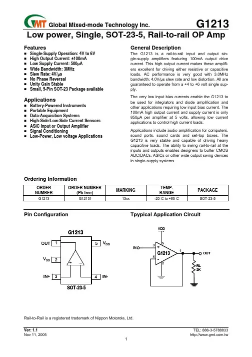
1/5 ISSUED DATE :2005/12/12 REVISED DATE : GQ2171 CMOS Positive Voltage Regulator Description The GQ2171 series of positive, linear regulators feature low quiescent current (50A typ.) with low dropout voltage and excellent PSRR, thus making them ideal for Telecommunications and other battery applications. These rugged devices have both Thermal Shutdown, and Current Fold-back to prevent device failure under the “Worst” of operating conditions. As an additional feature, the GQ2171 is stable with an output capacitance of just extended 0.22F or greater. Features Functional Block Diagram Very Low Dropout Voltage Guaranteed 150mA output Over-Temperature Shutdown Current Limiting Short Circuit Current Fold-back Excellent PSRR Type 70dB Noise Reduction Bypass Capacitor Power-saving Shutdown Mode Factor Pre-set Output Voltage Applications Battery Powered Widgets Instrumentation Wireless Devices PC Peripherals Portable Electronics Cordless Phones Electronic Scales Cellular Phones Cameras Telecommunications Package Dimensions Millimeter Dimensions REF. Min. Max. REF. Millimeter A 2.70 3.10 G 1.90 REF. B 2.60 3.00 H 1.20 REF. C 1.40 1.80 I 0.12 REF. D 0.30 0.55 J 0.37 REF. E 0 0.10 K 0.60 REF. F 0° 10° L 0.95 REF. Typical Application Circuit 元器件交易网www.cecb2b.com
2/5 ISSUED DATE :2005/12/12 REVISED DATE : Absolute Maximum Ratings Parameter Symbol Ratings Unit Input Max Voltage VIN 6 V Output Current IOUT PD/( VIN- VO) mA Output Voltage VOUT 1.5~3.3 V Operating Ambient Temperature Topr -40 ~ +85 Junction Temperature Tj -40 ~ +125 Maximum Junction Temperature Tj Max 150 Power Dissipation(T=100) PD 380 mW EDS Classification B Electrical Characteristics TA=25 unless otherwise noted (VOUT(T)>2.0V VIN=VOUT(T)+0.5V; VOUT(T)2.0V VIN=VOUT(T)+1V; VSHDN=VIN, CIN=COUT=1uF) Parameter Symbol Condition Min TYP Max Unit IO=0.1mA, VOUT(T)2.0V -1.0 1.0 IO=0.1mA, VOUT(T)<2.0V -1.5 1.5 Output Voltage VOUT(E) (Note1) IO=150mA -2.0 VOUT(T) (Note2) 2.0 % Current Limit ILIM VO>800mV 150 200 - mA Fold-back Current IFB VO=0V - 80 - A VOUT>2.0V VIN=VOUT(T)+0.5V -1 0.5 1 Load Regulation REGLOAD IO=0.1 to 150mA VOUT2.0V VIN=VOUT(T)+1V -2 - 2 % VOUT(T)2.0V - 300 500 1.8VVOUT(T)<2.0V - 700 1000 Dropout Voltage VDROPOUT IO=150mA VO=VOUT(E)-2% 1.5VVOUT(T)<1.8V - 900 1300 mV Quiescent Current IQ VIN=5V, IO=0mA - 60 - A Ground Pin Current IGND VIN=5V, IO=1mA to150mA - 50 - A IO=0.1mA, VOUT>2.0V VIN=VOUT(T)+0.5V to 5.5V -0.2 0.1 0.2 Line Regulation REGLINE IO=0.1mA, VOUT2.0V VIN=VOUT(T)+1V to 5.5V -0.4 - 0.4 % Input Voltage VIN Note3 - 5.5 V Over Temperature Shutdown OTS - 137 - Over Temperature Hysterisis OTH - 23 - Output Voltage Temperature Coefficient TC - 30 - ppm/ Power Supply Rejection PSRR Ro=100,Co=2.2mF, f=1kHz - 70 - dB Output Voltage Noise eN f=10Hz~100kHz, Io=10mA, Co=2.2F - 30 - Vrms VSHDNH VSHDN=0.8* VIN 0.8* VIN - VIN V SHDN Input Threshold VSHDNL VSHDN=0.6V 0 - 0.6 V SHDN Input Bias Current VIN=5V, EN=0v, or 5V - 0.01 - A Shutdown Supply Current ISD VIN=5V, VO=0V - 0.5 1 A Shutdown Output Voltage VO,SD Output Loading1200, Vo=0V 0 - 0.4 V Note 1: VOUT (E) =Effective Output Voltage (i.e. the output voltage when “VOUT(T)>2.0V VIN=VOUT(T)+0.5V; VOUT(T)2.0V VIN=VOUT(T)+1V; VSHDN=VIN” is provided at the VIN pin while maintaining a certain IOUT value). 2: VOUT (T) =Specified Output Voltage 3: VIN (MIN) =VOUT+VDROPOUT 元器件交易网www.cecb2b.com
3/5 ISSUED DATE :2005/12/12 REVISED DATE : Ordering Information ( contd. ) Part Number Marking Output Voltage Part Number Marking Output Voltage GQ2171-15 1K152 XXXX 1.5V GQ2171-18 1K182 XXXX 1.8V GQ2171-20 1K202 XXXX 2.0V GQ2171-25 1K252 XXXX 2.5V GQ2171-27 1K272 XXXX 2.7V GQ2171-28 1K282 XXXX 2.8V GQ2171-2H 1K2H2 XXXX 2.85V GQ2171-30 1K302 XXXX 3.0V GQ2171-32 1K322 XXXX 3.2V GQ2171-33 1K332 XXXX 3.3V Detailed Description The GQ2171 series of COMS regulators contain a PMOS pass transistor, voltage reference, error amplifier, over-current protection, and thermal shutdown. The P-channel pass transistor receives data from the error amplifier, over-current shutdown, and thermal protection circuits. During normal operation, the error amplifier compares the output voltage to a precision reference. Over-current and Thermal shutdown circuits become active when the junction temperature exceeds 150, or the current exceeds 150mA. During thermal shutdown, the output voltage remains low. Normal operation is restored when the junction temperature drops below 120. The GQ2171 switches from voltage mode to current mode when the load exceeds the rated output current. This prevents over-stress. The GQ2171 also incorporates current fold-back to reduce power dissipation when the output is short circuited. This feature becomes active when the output drops below 0.8 volts, and reduces the current flow by 65%. Full current is restored when the voltage exceeds 0.8 volts. External Capacitors The GQ2171 is stable with an output capacitance to ground of 0.22F or greater. Ceramic capacitors have the lowest ESR, and will offer the best AC performance. Conversely, Aluminum Electrolytic capacitors exhibit the highest ESR, resulting in the poorest AC response. A second capacitor is recommended between the input and ground to stabilize Vin. The input capacitor should be at least 1F to have a beneficial effect. A large capacitor improves the AC ripple rejection, but also makes the output come up slowly. This “Soft” turn-on is desirable in some applications to limit turn-on surges. All capacitors should be placed in close proximity to the pins. A “Quiet” ground termination is desirable. This can be achieved with a “Star” connection. Shutdown When actively, pulled low, the PMOS pass transistor shuts off, and all internal circuits are powered down. In this state, the quiescent current is less than 1A. This pin behaves much like an electronic switch. Characteristics Curve 元器件交易网www.cecb2b.com