专项设计指南(参考)
- 格式:pdf
- 大小:275.33 KB
- 文档页数:4

上海市建设工程设计文件审查办事指南(企业投资核准、备案类项目)二〇一一年三月目录上海市建设工程施工图设计文件审图公司抽取选定办事指南 (3)建设单位网上抽取选定审图公司密码申请表 (6)上海市建设工程施工图设计文件审图公司抽取情况通知单 (7)上海市建设工程设计文件审查办事指南 (8)上海市企业投资核准、备案项目建设工程设计文件审查流程图 (14)上海市建设工程设计文件审查申请表 (15)上海市建设工程设计文件审查收件单 (17)上海市建设工程施工图设计文件审查建设单位承诺书 (18)上海市建设工程设计文件审查(复审)受理通知书 (19)上海市建设工程设计文件审查(复审)不予受理决定书 (20)上海市建设工程设计文件审查(复审)补正材料通知书 (21)上海市建设工程设计文件审查(复审)中止办理期限告知书 (22)上海市建设工程设计文件审查(复审)终止办理通知书 (23)上海市建设工程施工图设计文件审查意见告知书 (25)上海市建设工程施工图设计文件审查整改通知单 (26)上海市建设工程施工图设计文件审查意见整改回复单 (27)上海市建设工程设计文件审查整改意见单 (28)上海市建设工程施工图设计文件审查复审办事指南 (33)上海市建设工程施工图设计文件审查复审申请表 (35)上海市建设工程施工图设计文件审查复审结果通知书 (36)上海市建设工程施工图设计文件审查合同备案办事指南 (37)上海市建设工程施工图设计文件审查合同备案表 (39)上海市建设工程施工图设计文件审查合同备案变更表 (40)上海市建设工程施工图设计文件审图公司抽取选定办事指南一、办理事项本指南适用于本市建设工程施工图设计文件审查审图公司的抽取、选定。
二、办理机构上海市建设工程设计文件审查管理事务中心(以下简称市审查中心)。
市办理窗口:办理地址:小木桥路683号底楼受理大厅一门式受理窗口21号(以下简称受理窗口)办理电话:54614788 - 1021办理时间:周一至周四(国家法定节假日除外)上午:9:00—11:30 下午:13:30—17:00周五(国家法定节假日除外)上午:9:00—11:30查询网址:咨询电话:54614788 - 1021区县所属管辖范围内项目到各区县相应机构办理。

浅谈城市雨水排涝专项规划设计【摘要】城市雨水系统作为城市的基础设施,近年来,随着城镇化进程加速,雨水系统建设滞后且标准偏低,导致雨水不能迅速排放,引发城市内涝问题。
规划好城市雨水排涝系统是城市未来可持续发展的内在需求,本文主要简述了城市雨水排涝专项规划设计思路。
【关键词】城市雨水排涝系统建设标准前言近年来,城市大规模发展的同时,雨水系统的建设却相对滞后,并没有与之相适应的雨水系统。
当城市遭受一次次暴雨来袭时,给我们的生活和生产造成了损失和不便,也使城市屡屡出现汽车“潜水”、市民“看海”的奇景,且每逢暴雨必有重要城市发生内涝,北京“7·21”和郑州“7·20”给人民群众造成巨大财产损失和人员伤亡的悲剧,同时,也暴露了我国城市雨水设施普遍存在的“短板”。
2015年10月,国务院办公厅发布《关于推进海绵城市建设的指导意见》,提出通过海绵城市建设,将70%的降雨就地消纳和利用。
因此,对城市雨水排涝工程进行建设规划时,应遵循“源头下渗减量、过程提标传输、末端调蓄排放”的理念进行规划设计,充分响应海绵城市的建设理念,补齐城市雨水设施短板,使经济建设、城市建设与环境建设同步规划、同步实施、同步发展,以实现经济效益、社会效益和环境效益的统一。
城市雨水排涝系统设计原则:(1)充分利用现状设施,因地制宜,优化系统。
根据城市建设发展方向,充分利用现状设施,统筹兼顾,保障城市水安全,提升城市排涝水平。
(2)合理确定雨水系统建设标准。
根据《室外排水设计标准》,结合城市规模确定雨水系统建设标准。
(3)技术先进、经济适用。
突出规划理念和技术的先进性,前期投资的合适性。
(4)统一规划、分步实施。
统一规划、分步实施,梯度推进项目建设,优先建设重点工程,充分发挥投资效益。
城市雨水排涝专项规划:1、城市雨水系统水力计算(1)城市雨水系统建设标准选择根据国家标准《室外排水设计标准》(GB 50014 - 2021),按照城市规模、重要程度,结合城市建设不同区域,选择雨水管渠不同的设计标准和内涝防治标准。
《需求规格说明书》编写参考指南1.概述(Summary)本文档是进行项目策划、概要设计和详细设计的基础,也是软件企业测试部门进行内部验收测试的依据。
1.1 用户简介(User Synopsis)在本章节中要将用户的基本情况描述清楚,以便于分析人员划定系统范围,进行功能、进度、成本、性能等方面的平衡决策。
对于产品开发类项目,需要在此将该产品定义的用户群的特点描述清楚。
1.2 项目的目的与目标(Purpose and Aim of Project)项目的目的是对开发本系统的意图的总概括。
项目的目标是将目的细化后的具体描述。
项目目标应是明确的、可度量的、可以达到的, 项目的范围应能确保项目的目标可以达到。
对于项目的目标可以逐步细化,以便与系统的需求建立对应关系,检查系统的功能是否覆盖了系统的目标。
1.3 术语定义(Terms Glossary)将该需求规格说明书中的术语、缩写进行定义, 包括用户应用领域与计算机领域的术语与缩写等。
1.4 参考资料(References)说明该用户需求报告使用的参考资料,如:[1] 商务合同[2] 招标书[3] 用户领域的资料[4] 用户需求调查表[5] 用户需求报告[6] 参照的标准每一个文件、文献要有标题、或文件号,发布或发表日期以及出版单位。
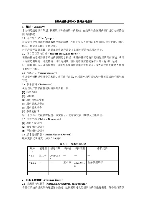
1.5 相关文档(Related Documents)[1] 项目开发计划[2] 概要设计说明书[3] 详细设计说明书1.6 版本更新信息(V ersion Updated Record)版本更新记录格式,如表5-19所示。
表5-19 版本更新记录2.目标系统描述(System in Target)2.1 组织结构与职责(Organizing Framework and Function)将目标系统的组织结构逐层详细描述,建议采用树状的组织结构图进行表达,每个部门的职责也应进行简单的描述。
组织结构是用户企业业务流程与信息的载体,对分析人员理解企业的业务、确定系统范围很有帮助。

Application Note AP1501A Series Step-Down (Buck) RegulatorThis application note contains new product information. Diodes, Inc. reserves the right to modify the product specification without notice. No liability is assumed as a result of the use of this product. No rights under any patent accompany the sale of the product.Contents1. Features2. Introduction3. Pin Functions4. Internal Block Diagram5. Regulator Design Procedure6. Design ExampleApplication NoteAP1501A Series Step-Down (Buck) Regulator1.0 Features◆Small Board Size- Entire circuit can fit on less than 2.5 square inches of PCB space◆Low Implementation Cost- Requires Only 10 External Components◆ON/OFF Control- Be controlled by external TTL logic level signal, low power standby mode◆Thermal Shutdown and Current Limit Protection- Built-in function◆Simple Feedback Compensation- Lead compensation using external capacitor◆Immediate Implementation- Schematic, board-of-materials and board layout available from Anachip2.0 IntroductionThis application note discusses simple ways toselect all necessary components to implement astep-down (BUCK) regulator and gives a design example.In this example, the AP1501A monolithic IC is used todesign a cost-effective and high-efficiency miniatureswitching buck regulator.This implementation is suitable for LCD TV and PDPTV applications. It can also be used in an off-linepost-regulator to convert the AC line voltage down to aDC voltage below 37V for a distributed power system.This demonstration board allows the designer toevaluate the performance of the AP1501A series buckregulator in a typical application circuit. The user needsonly to supply an input voltage and a load. Thedemonstration board can be configured to evaluate fixedoutput voltage of 3.3V, 5V, 12V, and an adjustable outputversion of the AP1501A series. Operation at othervoltages and currents may be accomplished by propercomponent selection and replacement.Application Note AP1501A Series Step-Down (Buck) Regulator3.0 Pin FunctionsNumber Name Function1 +VINOperating Voltage Input2 Output Switching Output3 GND Ground4 FB Output Feedback Control5 SDON/OFF Shutdown Control+VIN (Pin 1):This pin is the main power input to the IC. The range of operating voltage is from +4.5V to +40V. A suitable input bypass capacitor must be present at this pin to minimize voltage transients and to supply the switching current needs by the regulator.Output (Pin 2):Internal switch. The voltage at this pin switches between (SAT IN V V −+) and approximately-0.55 V, with a duty cycle of approximately IN OUT V V . To minimize coupling to sensitive circuitry, the PC board copper area connected to this pin should be kept at a minimum.GND (Pin 3):Circuit ground for the IC.FB (Pin 4):Senses the regulated output voltage to complete the feedback loop.SD (Pin 5):Allows the switching regulator circuit to be shutdown using logic level signals thus dropping the total input supply current to approximately 150uA. Pulling this pin below a threshold voltage of approximately 1.3V turns the regulator on, and pulling this pin above 1.3V (up to a maximum of 25V) shuts the regulator down. If this shutdown feature is not needed, the SD pin can be wired to the ground pin or it can be left open. In either case the regulator will be in the ON condition.Application NoteAP1501A Series Step-Down (Buck) Regulator4.0 Internal Block Diagram5.0 Regulator Design Procedure5.0.1Given Power SpecificationV IN(max)= Maximum Input VoltageV IN(min)= Minimum Input VoltageV OUT= Regulated Output VoltageV RIPPLE= Ripple Voltage (peak-to-peak), typical value is 1% of the output voltageI LOAD(max)= Maximum Load CurrentI LOAD(min)= Minimum Load Current before the circuit becomes discontinuous, typical value is 10% of theMaximum Load CurrentF= Switching Frequency (fixed at a nominal 150KHz)OSCApplication Note AP1501A Series Step-Down (Buck) Regulator5.0.2 Programming Output VoltageThe output voltage is programmed by the selection of the divider R2 and R3. The designer should use resistors R2 and R3 with ±1% tolerance in order to obtain best accuracy of the output voltage. The output voltage can be calculated from the following formula:⎟⎠⎞⎜⎝⎛+×=321R R V VREF OUT------------------------ (1)Where= 1.235VVREF⎟⎟⎠⎞⎜⎜⎝⎛−×=132V V REF OUT R R -------------------------- (2) Select a value for R3 between 240Ω and 1.5K Ω. The lower resistor values minimize noise pickup in thesensitive feedback pin. If the designer selects a fixed output version of the AP1501A, the formula (1) won't be applied, and then the resistor R2 shall be short and R3 shall be open.5.0.3 Inductor SelectionA. The minimum inductor can be calculated from the following design formula table:L(min)V SAT= Internal switch saturation voltage of the AP1501A. The saturation voltage increases with theconducting current. Typical value is 1.5 V.VF= Output rectifier forward voltage drop. Typical value for SB540 rectifier is 0.55V.B. The inductor must be designed so that it does not saturate or significantly saturate at DC current bias ofI PK. (I PK = Peak inductor or switch current = II LOAD LOAD (min)(max)+)Application Note AP1501A Series Step-Down (Buck) Regulator5.0.4 Output Capacitor SelectionA. The output capacitor is required to filter the output and provide regulator loop stability. When selecting an output capacitor, the important capacitor parameters are; the 100KHz Equivalent Series Resistance (ESR), the RMS ripples current rating, voltage rating, and capacitance value. For the output capacitor, the ESR value is the most important parameter. The ESR can be calculated from the following formula:⎟⎟⎠⎞⎜⎜⎝⎛×=I V LOAD RIPPLE ESR (min)2 ------------------------ (3) An aluminum electrolytic capacitor's ESR value is related to the capacitance value and its voltage rating.In most cases, higher voltage electrolytic capacitors have lower ESR values. Often, capacitors with much higher voltage ratings may be needed to provide the low ESR values required for low output ripple voltage. If the selected capacitor's ESR is extremely low, it results in an oscillation at the output. It is recommended to replace this low ESR capacitor by using two general standard capacitors in parallel.B. The capacitor voltage rating should be at least 1.5 times greater than the output voltage, and often much higher voltage ratings are needed to satisfy the low ESR requirements needed for low output ripple voltage.5.0.5 Compensation Capacitor SelectionFor output voltage greater than approximately 10V, an additional capacitor C1 is required. Thecompensation capacitor C1 provides additional stability for high output voltages, low input-output voltages, and/or very low ESR output capacitors.5.0.6 Output Rectifier SelectionA. The output rectifier D1 current rating must be greater than the peak switch current IPK. The reversevoltage rating of the output rectifier D1 should be at least 1.25 times the maximum input voltage.B. The output rectifier D1 must be fast (short reverse recovery time) and must be located close to theAP1501A using short leads and short printed circuit traces.Because of their fast switching speed and low forward voltage drop, Schottky diodes provide the best performance and efficiency, and should be the first choice, especially in low output voltage applications.Application Note AP1501A Series Step-Down (Buck) Regulator5.0.7 Input Capacitor SelectionA. The RMS current rating of the input capacitor can be calculated from the following formula table. The capacitor manufacturers data sheet must be checked to assure that this current rating is not exceeded.B. This capacitor should be located close to the IC using short leads and the voltage rating should be approximately 1.5 times the maximum input voltage.5.0.8 Thermal ConsiderationsInternal Thermal Shutdown circuitry is provided to protect the integrated circuit in the event that the maximum junction temperature is exceeded. When activated, typically at 150°C, the output switch is disabled. This feature is provided to prevent catastrophic failures from accidental device overheating. The maximum IC junction temperature shall not exceed 125ºC to guarantee proper operation and avoid any damages to the IC. The total power dissipated by the IC can be quantified as follows:S SAT Q LOSS P P P P ++=--------------------(4)Where:Q P : The power dissipation is due to quiescent current of the IC (10mA maximum).: The conduction loss occurs when the power switch turns on, the saturation voltage and SAT P conduction current contribute to the power loss of a non–ideal switch.: The switching loss occurs when the switch experiences both high current and voltage during each switch transition. S PThe thermal characteristics of AP1501A depend on the following four factors: junction temperature, ambient temperature, IC power dissipation, and the thermal resistance from the die junction to ambient air. The relation between temperature and heat radiation quantity is shown as follows:()LOSSA J JA P T TR (max)(max)−=θ --------------------(5)Application Note AP1501A Series Step-Down (Buck) RegulatorThe TO-220 package needs a heat sink that effectively increases the surface area of the package to improve the flow of heat away from the AP1501A and into the surrounding air. The total thermal resistance is comprised of three components. These resistive terms are measured from junction to case (), case to heat sink (), and heat sink to ambient air (). The equation is shown as follows: JC R θCS R θSA R θCS JC JA SA R R R R θθθθ−−= -------------------(6)Where:: The thermal resistance between the IC chip (junction point) and package backside connecting to the heat sink. The thermal resistance of 5-lead TO-220 package is approximately 2.5ºC/W.JC R θ : The thermal resistance of heat sink. This value depends on the heat sink type.SA R θCS R θ: The thermal resistance between the package backside and the heat sink including the condition ofsilicon grease and bolt tighten torque. Typical value is 0.5 ºC /W for a 5-lead TO-220 package with a standard silicon/zinc oxide thermal compound has thermal conductivities between 0.7 and 0.9 W/mK.The recommended bolt tighten torque is smaller than 6kg·cm (or 5.3 lb·in) for an M3 screw.Once these calculations are complete, the maximum permissible value of can be calculated and then select the heat sink whose is smaller than the result of equation (6). For more detail, please refer the thermal resistance value mentioned in the specification of the heat sink supplier.SA R θSA R θ5.0.9 PCB Layout ConsiderationsSpecial care should be taken to separate ground paths from signal currents and ground paths from load currents. All high current loops should be kept as short as possible using heavy copper runs to minimize ringing and radiated EMI. For best operation, a tight component layout is recommended. Input and output capacitors (C2, C3, C5, C6) and all feedback components should be placed as close to the IC as physically possible. It is also imperative that the Schottky diode connected to the Switch Output be located as close to the IC as possible.6.0 Design Example6.0.1 Summary of Target SpecificationsInput PowerV IN (max)= +19V;= +19VVIN (min)Regulated Output Power V OUT= + 5V;ILOAD (max)= 5A;ILOAD (min)= 0.5AOutput Ripple Voltage ≤VRIPPLE50 mV peak-to-peakOperation Temperature (max)J T =100℃; = 50℃(max)A T Efficiency75% minimum at full loadSwitching Frequencyf = 150KHz ± 15 %Application NoteAP1501A Series Step-Down (Buck) Regulator 6.0.2 Calculating and Components SelectionApplication Note AP1501A Series Step-Down (Buck) Regulator6.0.3 Parts List (Board of Materials)Item Part Number MFG/Dist.Description ValueQuantityC1Open 0C2, C3 GF331M035G160LUXONAluminumElectrolytic *330uF, 35V 2 C4Ceramic Capacitor0.1uF, 50V 1 C5, C6 KM102M010G160CAPXONAluminumElectrolytic *1000uF, 10V 2 C7 Ceramic Capacitor2200pF, 50V1 D1 SB540 HAWYANG Schottky Diode * 40V, 5A 1J1 Terminal Block Pitch=5.08mm, 2pin 1 J2Terminal BlockPitch=5.08mm, 3pin1 L1 3011I56 FRONTIERInductor *25 UH, 5A 1 U1 AP1501A-50T5 AnachipPWM BuckConverter *150KHz, 5A 1 R1 Std Film Chip Resistor 10Ω±5%, 1/8W1R2Short 0R3 Open 0 HS1 MI-317 MEICON Heat Sink W =50.7mm,H =25.2mm 1 EG-30 E.G-BOND Silicone Compound 0.9 W/m K * X1~X4 MF-005-N2W Pin Good Spacer Support Hole in P .C.B Φ3.5 4 * You should apply a very thin (paper thin) layer on the heat sink before installing AP1501A. Don't use too much - the thinner the layer, the better.* Manufacturers and Distributor Contact Information:Phone +886-2-2655-1818 Fax +886-2-2655-1616 Anachip Corp.易亨電子股份有限公司Website Phone +886-2-2914-7685~9 Fax +886-2-2918-6304 FRONTIER Electronics Co., LTD 弘電電子工業股份有限公司 Website Phone +886-2-2219-0903 Fax +886-2-2219-3189 HAWYANG Electronics Co., LTD 浩陽有限公司Website Phone +886-2-2621-8949 Fax +886-2-2621-2440 MEICON Electronics IND. Co., LTD 永聯電子工業股份有限公司Website Phone +886-2-86926611 Fax +886-2-86926481 CAPXON Electronic Industrial Co., LTD 豐賓電子工業股份有限公司Website Application Note AP1501A Series Step-Down(Buck) Regulator11/12ANP006 – App. Note 1 Jun 2006 6.0.4 Demo Board Schematic© Diodes IncorporatedApplication Note AP1501A Series Step-Down (Buck) Regulator12/12ANP006 – App.Note 1 Jun 2006 6.0.5 Typical PC Board Layout, Adjustable Output: (1x Size)(1). Component Placement Guide (2). Component Side PC Board Layout(3). Solder Side PC Board Layout© Diodes Incorporated。

中铁十四局集团有限公司目录1编制说明 (5)1.1编制依据 (5)1.2编制原则 (5)1.3使用范围 (5)2 工程概况及地质条件 (6)2.1工程概况 (6)2.2工程地质条件 (6)2.3 施工重难点和关键技术 (7)3 施工部署及资源配置情况 (7)3.1 总体施工原则 (7)3.2总体施工方案 (7)3.3主要资源配置及临时设施 (7)3.3.1主要人员配置 (7)3.3.2机械设备配置 (8)4总体施工方案、方法及管理控制措施 (9)4.1模板设计 (9)4.1.1 外模板构造的设计 (10)4.1.2 内模设计 (11)4.1.3 工作平台 (13)4.1.4爬梯设置 (14)4.2 工艺原理 (14)4.3 主要施工方法 (17)4.3.1 钢筋连接作业工艺 (17)4.3.2 混凝土施工 (19)4.3.3 空心墩底部实体段施工 (21)4.3.4 空心墩的封顶施工 (22)4.3.5 墩身养护 (24)4.3.6墩身翻模施工循环时间表 (24)4.4墩身检查梯的安装 (25)4.4.1检查梯的选择 (25)4.4.2检查梯的安装 (25)4.5吊装方案 (26)5 测量方案 (27)5.1 平面控制测量 (28)5.2 高程控制测量 (28)5.3 施工放样 (28)5.4墩身线性控制 (29)5.4.1控制方法 (29)6工期计划安排 (30)6.1工效进度指标 (30)6.2施工进度计划 (30)6.3工期保证措施 (32)6.3.1 组织措施 (32)6.3.2技术措施 (33)7 混凝土外观质量控制 (35)7.1墩身表面质量通病的防治 (35)7.2 模板接缝、分层和分节施工缝的消除 (35)7.3墩身防扭曲控制 (36)7.4砼表面裂缝的预防 (36)8 质量保证措施 (37)8.1质量保证体系 (37)8.2 质量保证措施 (39)8.2.1 质量管理制度 (39)8.2.2 质量保证控制措施 (41)8.2.3 隐蔽工程质量保证措施 (43)8.2.4 控制和防止工程质量通病的措施 (44)8.3 冬季施工措施 (45)8.4 夏季施工措施 (47)8.5 雨季施工措施 (50)9 安全保证措施 (51)9.1安全保证措施 (51)9.1.1安全管理组织机构 (52)9.1.2安全保证体系 (52)9.1.3安全管理制度 (53)9.2安全保证措施 (54)10 施工成本控制措施 (59)10.1严格组织施工 (59)10.2 严格控制成本 (59)10.3 制度建设 (59)10.4加强合同管理 (59)10.5施工计划管理 (59)10.6财务管理 (60)10.7加强物资管理,努力降低建设成本 (60)10.8临时设施建设标准 (60)10.9落实征地拆迁部省纪要,明确各方职责,从严控制相关费用 (60)11 环保、水土保持措施 (60)11.1 环境保护和水土保持目标 (60)11.2 建立健全施工环保、水土保持管理组织机构与保证体系6011.2.1 建立专职的环保、水保管理组织机构 (60)11.2.2 建立健全环保、水保管理体系,强化环保管理 (61)11.3 施工环境保护措施 (62)11.3.1 临时工程环保措施 (63)11.3.2弃砟场环保措施 (63)11.3.3 废水、废渣处理措施 (63)11.3.4防止空气污染和扬尘措施 (64)11.3.5 施工噪音控制措施 (64)11.3.6 对沿线河流、湖泊及水库的施工环保措施 (64)11.3.7 施工水土保持措施 (64)12 文明施工措施 (65)12.1文明施工目标 (65)12.2文明施工体系 (65)12.3文明工地建设 (66)12.4文明施工管理措施 (67)13与相关方的协调配合工作 (68)13.1与参见单位的协调配合工作 (68)13.2与地方政府的协调配合工作 (69)14 附件一《空心墩封顶施工检算资料》 (69)附件二《高墩模板检算书》 (69)附件三《爬梯结构验算书》 (69)附件四《塔吊安装方案》 (69)高墩墩身专项施工方案1编制说明1.1编制依据(1)《客货共线铁路桥涵工程施工技术指南》TZ 203-2008;(2)《铁路混凝土工程施工技术指南》铁建设【2010】241号;(3)《铁路桥涵工程施工质量验收标准》TB10415-2003;(4)《铁路混凝土工程施工质量验收标准》 TB10424-2010;(5)国家现行有关施工规范、验收标准及相似工程施工经验;(6)新建黔张常铁路革勒车特大桥工程施工图第三册《桥墩及基础》;(7)新建黔张常铁路《大中桥设计图》第一册;(8)新建黔张常铁路连续梁桥墩参考图图号:黔张常施桥参11;(9)新建一次复线铁路(线间距≤5m)圆端形空心桥墩跨度:Lp=32+32m (直曲线)图号:黔张常施桥参6。

附件11耀24튨゜2021 ㈠ 㜮′〲⸹㔴为落实“十四五”期间国家科技创新有关部署安排,国家重点研发计划启动实施“国家质量基础设施体系”重点专项。
根据本重点专项实施方案的部署,现发布2021年度项目申报指南。
本重点专项总体目标是:面向世界科技前沿、面向经济主战场、面向国家重大需求、面向人民生命健康,围绕质量强国、科技强国、健康中国、数字中国等重大国家战略需求,加强国家质量基础设施体系量子化、国际化、智能化、数字化、系统化建设。
2021年度指南按照“基础研究—关键技术—集成示范”三个层次,进行全链条设计、一体化实施,围绕基础前沿和战略任务研究、关键共性技术研发、场景应用及示范3大方向进行部署,拟支持21个重点任务,拟安排国拨经费概算4.82亿元。
其中,拟部署不超过6个青年科学家项目,拟安排国拨经费概算1200万元,每个项目200万元。
项目统一按指南二级标题(如1.1)的研究方向申报。
除特殊说明外,同一指南方向下,如未明确支持项目数,原则上只支持—282—1项,仅在申报项目评审结果相近、技术路线明显不同时,可同时支持2项,并建立动态调整机制,根据中期评估结果,再择优继续支持。
所有项目均应整体申报,须覆盖全部研究内容和考核指标。
项目执行期原则上为3~5年。
项目下设的课题数不超过5个,项目参与单位数不超过10家。
项目设1名负责人,每个课题设1名负责人。
青年科学家项目支持青年科研人员承担国家科研任务,可参考重要支持方向(标*的方向)组织项目申报,但不受研究内容和考核指标限制。
青年科学家项目不再下设课题,项目参与单位总数不超过3家。
项目设1名项目负责人,青年科学家项目负责人年龄要求,男性应为1983年1月1日以后出生,女性应为1981年1月1日以后出生,原则上团队其他参与人员年龄要求同上。
本专项2021年度项目申报指南如下。
1.信息技术与人工智能领域NQI协同创新1.1基于D-SI的数字质量基础设施关键技术研究及体系建立研究内容:研究基于数字国际单位制(D-SI)的数字质量基础设施关键技术,研制符合可发现、可获取、可互用、可复用(FAIR)规则的NQI数字框架,研制测量数据的数字化规范、国际互认机器可读数字校准证书的结构规则及参考实例,建立面向—283—NQI实体的数字身份管理规范和基于可信时间戳的信息安全系统,开展基于D-SI用于数字转换的安全可靠校准测量系统的应用研究。
illustrator的参考文献Illustrator是一款广泛应用于设计领域的矢量图形软件,它的应用范围涵盖了很多设计领域,如平面设计、包装设计、插画制作等。
在学习和使用Illustrator过程中,参考文献是我们学习探索的重要来源之一。
下面,我将介绍一些Illustrator的参考文献以帮助大家更好地了解和使用这款软件。
1. 《Adobe Illustrator CC教程》(附DVD)作者:[美] 皮萨诺这本教程是一本独立的教材,旨在通过实例操作,让读者了解并掌握Illustrator CC软件的基本应用。
教程分为13章,从Illustrator基础、字体和排版、描绘技巧、绘图技巧、变形技巧、渐变和纹理、路径和剪贴蒙版、创新设计、3D效果等方面进行详细讲解。
该教程通过示例和案例演示的形式,帮助读者了解这些技术和功能的作用和用法。
2. 《Adobe Illustrator CC入门与精通》(第3版)作者:尹立青这本书是Illustrator CC的入门和进阶指南,适合初学者和进阶用户使用。
书中详细介绍了Illustrator的操作和功能,包括基本绘图和编辑技巧、形状、颜色和渐变的应用、路径和节点的编辑、文本和排版、3D和透视、图形转换和效果、图形输出和导出等方面的知识点。
此外,作者还通过实验和示例提供一些实用技巧,帮助读者更好地理解和掌握Illustrator的应用。
3.《Illustrator从入门到精通》(第2版)作者:(韩)Kyung-il Seo这本书是一本Illustrator入门从入门到精通的指南,适合初学者和进阶用户使用。
书中详细介绍了Illustrator的操作和应用,包括工作界面、绘图基础、形状、颜色和渐变、路径和剪切蒙版、对象和图层、文本和字体、3D和效果、图形输出和导出等方面的知识点。
此外,作者还提供了许多实用、有趣的示例和技巧,帮助读者掌握Illustrator软件的应用。
桥⾯系设计指南《公路⼯程咨询设计指南》——桥⾯系⼀、桥⾯系设计指南内容本指南纳⼊进如下内容:1、桥⾯防⽔2、伸缩缝3、栏杆4、灯柱5、⼈⾏道6、搭板7、泄⽔管8、砼防撞栏其中,砼防撞栏于2005年形成了院通⽤图。
⼆、设计输⼊:2.1 技术标准与设计规范:[1]《公路⼯程技术标准》(JTG B01-2003);[2]《公路桥涵设计通⽤规范》(JTG D60-2004);[3]《公路钢筋混凝⼟及预应⼒混凝⼟设计规范》(JTG D62-2004);[4]《公路桥涵施⼯技术规范》(JTJ 041-2000);[5]《公路交通安全设施技术规范》(JTG D81-2006);[6]《预应⼒混凝⼟⽤钢绞线》(GB/T5224-2003);[7]《钢筋混凝⼟⽤热扎光圆钢筋》(GB 13013-1991);[8]《钢筋混凝⼟⽤热扎带肋钢筋》(GB 13014-1998);[9] 交通部部颁⾏业标准《公路桥梁伸缩装置》(JT/T 327-2004);[10]《⾼速公路交通⼯程及沿线设施设计通⽤规范》(JTG D80-2006);[11]《公路交通安全设施设计规范》(JTG D81-2006);[12]《公路交通安全设施设计细则》(JTG/T D81-2006);[13]《公路桥涵施⼯技术规范》(JTJ 041-2000);[14]《公路⽔泥混凝⼟路⾯设计规范.》(JTG D40-2003);[15]《公路沥青路⾯设计规范》(JTG D50-2006);[16]《公路排⽔设计规范》(JTJ 018-96);[17]《铁路钢桥保护涂装》(TB/T1527);[18]《路桥⽤材料标准九项》(TB/T1527)。
2.2 资源准备2.2.1 资料:[1] 前阶段的研究成果和资料;[2] 设计规范和标准的掌握和理解;[3] 院防撞栏及桥梁上部结构断⾯布置通⽤图(试⽤版)、桥⾯系附属设施设计参考图(试⽤版);[4] 具体项⽬的咨询、审查意见及施⼯反馈;2.2.2 计算软件:[1] Midas Civil 2006[2] 桥梁博⼠V3.1[3] 公路桥梁结构设计系统GQJS9.7[4] 院⾃编的路⾯排⽔⽔⼒计算等附属⼩程序。