IPG高功率激光器夏季操作注意事项
- 格式:pdf
- 大小:316.00 KB
- 文档页数:2
ipg激光原理
IPG激光原理是指IPG(IPG Photonics Corporation)激光器的工作原理。
IPG激光器使用的是光纤激光技术,主要包括光纤增益介质、泵浦光源、光纤输出等组件。
IPG激光器使用的增益介质是光纤,通过泵浦光源激发光纤中的掺铥等杂质,从而实现激光放大。
泵浦光源通常采用高功率二极管激光器。
在IPG激光器中,泵浦光源发出的光通过耦合器进入光纤,进而被光纤中的掺杂杂质吸收。
这些被吸收的光子激发了掺杂材料中的电子跃迁,从而实现能量的存储。
当能量存储足够时,光纤中的掺杂材料开始释放能量,发出激光。
激光从光纤中传输,并最终通过光纤输出端口输出。
IPG激光器具有高效、稳定、可靠的特点,因此在工业、医疗和科学研究等领域广泛应用。
ipg光纤激光器功率衰减
IPG光纤激光器的功率衰减通常由以下因素造成:
1. 光纤的损耗:光纤本身存在传输损耗,即光信号在光纤中传输过程中会受到一定的衰减。
通常,单模光纤的损耗较小,而多模光纤的损耗较大。
2. 光纤连接件的损耗:光纤连接器和衰减器等连接件也会引入一定的功率损耗。
3. 光纤的弯曲和拉伸:当光纤被弯曲或拉伸时,会导致光信号在光纤中的损耗增加。
4. 光纤的污染和损伤:污染和损伤会导致光纤表面的反射和散射增加,从而引起光信号的衰减。
5. 温度变化:光纤的传输特性会随着温度的变化而发生变化,从而引起功率衰减。
需要注意的是,IPG光纤激光器的功率衰减与其输出功率和波长等参数也有关系,不同的光纤激光器会有不同的功率衰减特性。
高功率IPG光纤激光器应用简介一、IPG光纤激光器简介1.光纤激光器简介光纤激光器是指用掺稀土元素玻璃光纤作为增益介质的激光器,光纤激光器可在光纤放大器的基础上开发出来:在泵浦光的作用下光纤内极易形成高功率密度,造成激光工作物质的激光能级“粒子数反转”,当适当加入正反馈回路(构成谐振腔)便可形成激光振荡输出。
2.光纤激光器的优势首先是使用成本低,光纤激光器替代了不稳定或高维修成本的传统激光器。
其次,光纤激光的柔性导光系统,非常容易与机器人或多维工作台集成。
第三,光纤激光器体积小,重量轻,工作位置可移动。
第四,光纤激光器可以达到前所未有的大功率(至五万瓦级)。
第五,在工业应用上比传统激光器表现更优越。
它有适用于金属加工的最佳波长和最佳的光束质量,而且光纤激光器在每米焊接和切割上的费用最低。
第六,一器多机,即一个激光器通过光纤分光成多路多台工作。
第七,免维护,使用寿命长。
最后,由于其极高的稳定性,大大降低了运行中对激光质量监控的要求。
简单来说就是高功率下的极好光束质量,高光束质量下的极好电光效率,高功率高光束质量下的极小体积、可移动性和柔性。
3.IPG简介全球最大的光纤激光制造商IPG Photonics由Valentin Gapontsev博士于1991年创建,总部设在美国东部麻省。
IPG在德国、美国、俄罗斯和意大利设有生产、研发基地,并在全球设有销售和服务网点,覆盖美国、英国、欧洲、印度、日本、韩国、新加坡和中国,并于2006年在美国纳斯达克上市。
十八年来,IPG致力于纵向合成,所有的核心配件均为IPG研发、生产和拥有,同时也是唯一一个能为客户提供高性价比的光纤和半导体激光器的厂家。
高功率是IPG的优势。
全世界已有上千台IPG的高功率(>1KW)光纤激光器在汽车制造、船舶制造、海上平台和石油管道、航空航天和技术加工等工业领域中得以应用。
在日本,我们向丰田、三菱、住友在内的客户售出了数百台IPG的大功率光纤激光器。
ipg 激光器工作原理
IPG激光器工作原理基于光纤激光器的原理。
光纤激光器由一
个光纤光束和激光介质组成。
工作原理如下:
1. 激光介质:激光介质通常是由具有较高折射率的柴甲结构中的掺杂离子组成,如氦、氖、铝等。
激光介质被激励后会产生光子释放,通过受激辐射而形成光放大区域。
2. 光泵浦:光泵浦是通过光源将光能转换为激光器的能量输入方式。
可以使用电子束加热,光电效应、等离子体、过电流、光化学反应、光化学反应、等方式来进行光泵浦。
3. 光纤光束:激光束是由光纤导出的一束高亮度,高功率激光束。
光纤通过激光器的传输光束被导入激光介质,并且光通过激光介质的激光介质形成一束相干光,然后被传输等。
4. 工作原理:激光介质在光泵浦的作用下,发生受激辐射作用,光子发生向下辐射,并与其他光子相互作用。
光子与其他光子相互作用后,光子被引导到一个放大器中并通过速度恢复窗口传播。
5. 输出功率:最终,通过不断的受激辐射和放大,激光器可以输出高功率激光束。
输出功率通常由激光器的设计和激发源的能量来决定。
输出功率可以达到几千瓦或更高。
总之,IPG激光器是利用光纤激光器的工作原理,通过光泵浦
和激光介质的相互作用,产生高亮度、高功率的激光束。

目录一、组成部分介绍 (2)1.控制主机介绍 (3)2.控制块介绍 (5)二、安装布局 (6)1.主机安装尺寸 (6)2.安装布局 (6)三、接线图 (7)IPG振镜一、组成部分介绍振镜由控制主机、控制块以及振镜头三个部分组成。
(图片为一楼展厅4工位现场图)1.控制主机介绍1端口:24V供电端,自带插头,需配线,接到控制柜24V端子排:4X0.75mm2;A2:+24V, A3:0V;A4:+24V ,A5:0V;A1保留。
2端口:网口,需配网线,连接到上位机PC端,需在PC端安装相应的软件,购买振镜时软件存在配套的U盘里面;具体安装使用见《IPG HP Scanner 简明使用手册》文档。
通过软件与PC端连接时,振镜主机IP地址自动分配,可以不需要设置;3端口:控制主机连接到振镜控制块SCAN端,自带连接线缆(振镜内部连接)4端口:15PIN,激光器控制端,需配线和配插头(主机端为公头,配线时要用母头),需要配两根线缆。
注意:1.9引脚为模拟量控制端口,需要用屏蔽双绞线;3引脚红光控制不接,振镜本身有一个红光需要控制,再控制激光器导引红光不方便操作,还是用PLC来控制导引红光。
即接:1.2.4.5.9.10.11.12引脚即可,其他引脚不接。
接头的金属外壳焊一根线接到激光器XP4 PE针脚。
线缆1:2.4.5.10.11.12(6芯);线缆2:1.9.模拟量信号地(3芯)5端口:控制主机连接到振镜头,自带连接线缆,该线缆标配3M,加长款5M(振镜内部连接)。
6端口:RS232通讯端口,不接线2.控制块介绍SCAN INTERFACE端与控制主机3端口连接,自带线缆(振镜内部连接)ROBOT INTERFACE端与PLC连接信号交互,自带插头,需配线1.2.13.14.23.24都要接0V, 21、22接24V。
组选择3-11相当于激光器的程序号码,根据组选择输入调用振镜控制软件上的组号。
3-11引脚根据实际需要的组数接对应数量的线缆,可以不需要全部接线。
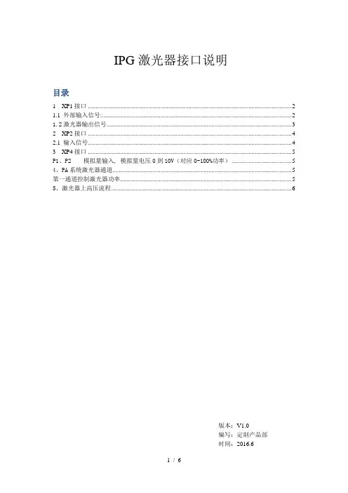
IPG激光器接口说明目录1 XP1接口 (2)1.1 外部输入信号: (2)1.2激光器输出信号 (3)2 XP2接口 (4)2.1 输入信号 (4)3 XP4接口 (5)P1、P2 模拟量输入, 模拟量电压0到10V(对应0-100%功率) (5)4、PA系统激光器通道 (5)第一通道控制激光器功率 (5)5、激光器上高压流程 (6)版本:V1.0编写:定制产品部时间:2016.61 XP1接口1.1 外部输入信号:Laser Request(激光器请求)高电平有效外部控制时此位必须置1,无此信号输入时其它输入信号都会被忽略。
控制器发出此信号时激光器会发出应答信号,B7(Laser assigned)置为高电平。
A2 Program start (程序启动)高电平有效,控制激光程序起动和停止。
程序号由A8到A14定义。
如果程序号是0000000和A6为高电平,那么激光器由模拟量控制A3 Internal Control Enabled 内控使能,高电平有效A4 Rest error(复位错误)高电平有效复位激光器系统的所有错误信息和激光器输出的错误信号,输入激活时间至少持续1ms。
A5 Guide laser ON (引导激光开启)A6 Analogue control ON(模拟量控制激活)高电平有效激活时程序号要为0000000A16 公共地C1 Laser ON (激光器电源开启)用于打开和关闭激光器主电源,如果主电源不能开启,B13(Warming output)会被置1. 如果主电源开启,输出 B8(Laser ON)会置1.C3至C6 双光纤通道选择 C3 最低位,C6最高位0000→Home position0001→通道10010→通道21.2激光器输出信号B1 Laser Ready(激光器准备好)高电平有效B2 Emission ON 高电平有效激光器光闸打开,正在出光B3 Internal control enabled 高电平有效内控使能B4 Laser Error(激光器错误)B5 Guide Laser is ON 红光打开时置1B6 Analogue Control is ON 模拟量控制模式时置1B7 Laser is assigned 激光器应答信号高电平有效。

USBLMC_CUH_IPG_V1(4)USBLMC Client Use HandbookIPG BoardCatalogSafety During Installation And Operation (1)Summarize (2)Ways to differentiate modules (3)I.Functions of Fiber Module(IPG)and Definitions of Pins (3)1.Features (4)2.Output Socket Definitions (4)3.Definition of Output Socket Pin (5)a.CON1:DB15Galvo Output (5)b.CON2:DB25Fibre socket (6)c.CON3:DB9Marking-on-fly Encoder (7)d.CON4:DB15Power (8)e.CON5:IDC10Socket (10)4.Jumper Illustration (11)5.Hardware Connection (13)a.Input signal IN0,IN8,Start,EMSTOP (13)b.Input signal IN5,IN9 (13)b.Power Connection (14)c.Typical Connection of Fiber Laser Module (16)II.The common connection ways (16)1.The connection between User-defined digital Galvo conversion board&USBLMC control card (16)2.The encoder,photoelectric switch during marking-on-fly (18)Safety During Installation And OperationPlease read these operating instruction completely before you proceed with installing and operating this product.If there are any questions regarding the contents of this manual,please contact BJJCZ.1.Steps For Safe Operation�Carefully check your application program before running it.Programming errors can cause a break down of the system.In this case neither the laser nor the scan head can becontrolled.�Protect the board from humidity,dust,corrosive vapors and mechanical stress.�For storage and operation,avoid electromagnetic fields and static electricity.These can damage the electronics on the product.For storage,always use the antistatic bag.�The allowed operating temperature range is25℃±10℃.�The storage temperature should be between–20℃and+60℃.ser Safety�This product is intended for controlling a laser scan system.Therefore all relevant laser safety directives must be known and applied before installation and operation.Thecustomer is solely responsible for ensuring the laser safety of the entire system.�All applicable laser safety directives must be adhered to.Safety regulation may differ from country to country.It is the responsibility of the customer to comply with all localregulations.�Please observe all laser safety instructions as described in you scan head or scan module manual,and this manual.�Always turn on the power of this product and the power supply for the scan head first before turning on the laser.Otherwise there is the danger of uncontrolleddeflection of the laser beam.We recommend the use of a shutter to prevent uncontrolled emission of laserradiation.SummarizeUSBLMC marking control card is developed specially for marking machine,it adopt USB interface BLMC marking control card is made up of two PCB board:Main-board and IO board.Main board and IO board are connected by two sockets which with50pins.The main-boards are the same,the IO board is divided into three different kinds by application:Optic fiber module(IPG),common digital module,and common analog module.Among them,common digital module is with a conversion board.Features of USBLMC�PowerUSBLMC marking control card uses5V power.We suggest adopt the power of5V/3Ato achieve power mon digital module,common analog interface’s powerinput signal is on CON2socket of module;and the power input signal of the optic fibermodule is on CON4socket of module.Please check the corresponding instruction ofPINS.�The laser Control1)Offer3routes TTL signal:Laser Gate,PWM,FPK for laser ser Gatesignal used for controlling switch of laser;PWM signal can be regarded as PWMsignal in CO2laser machine or the repeated pulse frequency in Nd:Yag lasermachine;FPK is for the first pulse inhibits signal in YAG laser machine.2)Offer2routes that are used for controlling the power of the laser power supply andrepeated pulse frequency of Q switch.3)As to the YLP series of pulse optic fiber laser machine of IPG,which is supplyspecial control signal.4)Laser Gate,PWM signal can be set up into high level available or low levelavailable.5)Common digital module,common analog module can be used for pre-setting theoutput power of the laser power supply.�Common digital input/output signal(TTL signal)There are10routes input and7routes output mon digital signal is dividedinto two kinds,switch form of input signal(no need external power)and non-switchform of input signal(external component entities supply the electric current drive).Common output signal is belong to TTL output(Without optical-isolation),the maxoutput electric current is15mA.Note:"The inputs/outputs signal"of this manual are all for USBLMC control card.The signals receiving by the USBLMC and driving by external component is inputsignals;signals driving by USBLMC control and receiving by external component isoutput signals.�Support multi-card working pattern.One computer can control8sets of USBLMC at a time,makes and marks the control board to run side by side and operate.Differentcontents can be processed by8sets of control cards.�Marking-on-flyFlying encoder can be connected to do real-time liner speed checking for good result ofhigh speed marking.�Extend axis(step motor/servo electrical motor)outputCan output two directions/pulse signals of channels to control step motor(or servoelectrical motor),applicable to pivot or join.�Start signalUsed when marking contents are the same and high speed is required.The Floor pushcan connect to Start signal,or to the common input signal as well.If there are variablesin marking content,they have to be connected to the common input signal.�Compatible with USB2.0/USB1.0Ways to differentiate modulesThere are some texts at the right-bottom corner of the er can differentiate them by them.The contents are:I.Functions of Fiber Module(IPG)and Definitions of PinsEach module is developed according the different applications.Therefore,its serial number,pin definition,jumper setting,and functional settings can vary.When in use please make sure to refer to the instructions of each particular type of module.For example,5V power input signal of USBLMC,on the common digital module and common analog module,should be inserted from12/13/24/25of the feet on CON2socket;while on the optic fiber module,the power input signal is connected from4/5/12/13of the feet on CON4 socket.1.Featuresa).Specially set for the YLP pulse laser by IPG Company.CON2-DB25pin is directlyconnected with the laser cube’s25-stitch pin.b).Digital IO signal,with1-way common output and3-way common input signals.IN0/IN1are fixed as the input at fiber laser status;IN6as the emergency-stop signal input for fiber laser.IN7is to check whether the power of laser marking machine is turned on or off;IN2/3/5are not applicable.IN4/8/9are comment input signals.For specific connections and the suggested connections,please see the section“Digital IO Connection Instructions”.OUT0is the common output;OUT2s fixed as the red light of fiber laser;OUT3is fixed as laser enabled.OUT1,and OUT4~6are not used.c).Output X-axis step motor to control signals.Y/Z axis cannot be output.d).Connect rotary encoder for high speed marking.e).Galvo output signals are digital outputs and can be set as non-encoded digital signal outputs,or set as digital signal outputs with extend codes.2.Output Socket DefinitionsFig.1-1Fiber Module–Socket Illustration3.Definition of Output Socket Pina.CON1:DB15Galvo OutputGalvo signals are digital signals which can be directly connected to digital Galvo.Digital galvo’s signals transfer protocols are not exactly the same,therefore,it should be confirmed which type of transfer protocols is used by the digital galvo.The company also provides transfer boards,which are analog boards transferred from digital.It can also be transferred analog signal outputs and connected to analog galvo.Fig.1-2CON1of Fiber IO boardPin No.Signal name Illustrations1,9CLK-/CLK+Clock signal.Difference output2,10SYNC-/SYNC+Synchronized signal.Difference output3,11XChannel-/XChannel+Digital signal of X axis galvo.Difference output4,12YChannel-/YChannel+Digital signal of Y axis galvo.Difference output5,13ZChannel-/ZChannel+Digital signal of Z axis galvo.Difference output6,14Status-/Status+The state feedback signal of Galvo.Difference input8,15Gnd The reference ground of control card.For the common two-dimension Galvo,only connecting CLK,SYNC XChannel,Ychannel four groups with8signal lines is enough.We suggest use twisted-pair(such as net-line)for connecting for digital signal.b.CON2CON2::DB25Fibre socketCON2socket and optic fiber25stitch socket of laser instrument connect through25stitch rows of line directly.Fig.1-3Pins of CON2Pins Signal name Illustrations1——8P0——P7Laser power.TTL output.9PLATCH Power latch signal.TTL output.10,14Gnd Control card’s Ground11,12Ver2:GND Control card’s Ground Ver3:SGIN2,SGIN3Laser status input.13,15,24Ver2:GND Control card’s Ground Ver3:NULL Reserved16,21SGIN4,SGIN1Laser status input.17Vcc5V power output of control card.18MO Master Oscillator switch.TTL output 19AP Power amplifier.TTL output.20PRR Repeat pulse power signal.TTL output.22Out2Laser’s red light indication signal.TTL output.23EMSTOP Emergency stop signal.TTL output. 25NULL Reservedc.CON3:DB9Marking-on-fly EncoderFig.1-4Pins of CON3PIN No.Signals Illustrations1IN8Common input signal8.Forms a return circuit with GND9. To use this signal,connect it and GND respectively to either terminals of power.2,6IN9+/IN9-TTL input signal.Internal1K current-limited resistor. External current-limited resistor is suggested when voltage is over12V.Please refer to IN9Port Illustration.3,7BCODEN/BCODEP Encoder phase B input signal.Differential input. 4,5ACODEN/ACODEP Encoder phase A input signal.Differential input. 8Vcc Control card5V output.9Gnd Control card Ground.As the return circuit signal of pin8& 1.d.CON4:DB15PowerFig.1-5Fiber Interfere Board CON4Socket Signals and the definitions PIN No.Signals Illustrations1SGIN0Common input signal0.Forms a return circuit with ground 12and13of the control board.To use this signal,connect it and the ground respectively to either terminal of the power.This is an input signal.2EMSTOP Emergency-stop signal.Forms a return circuit with ground 12&13.To use this signal,connect it and the ground signal respectively to either terminal of the NORM-OPEN switch.When this EMSTOP is pressed,it means there is emergency and operation is immediately stopped.The signal is an input signal.3Ver2:POW_BTN Power signal of the laser instrument main power source. Forms a return circuit with the Ground12&13of the control board.To use this signal,connect it and the Ground signal respectively to either terminal of the NORM-OPEN switch.When the power button is pressed downward,pin 10&11are connected;when the button is bounced upwards,they are disconnected.For the power connection, see“Power Connection”.This is an input signal.Ver3:NULL Reserved4,5VCC5V input power positive terminal.This is an input signal.8START Start signal.Forms a return circuit with Ground12&13. To use this signal,connect it and the Ground signal respectively to either terminal of the power.This is an input signal.9OUT0Common output es GND12&13signals as reference signals.This is an output signal.10,11Ver2:POW_CON,POW_CON1Connection port of power relay.Connect POW_CON to theanode of power relay’s control power.One of the powerrelay’s control ports should be connected withPOW_CON1,and the other to the cathode of the cathode ofpower relay’s control power.When the3-point power isplugged in,POW_CON and POW_CON1are connected.At that time,power relay’s control port is connected to itscontrol power,power relay picks up,and fiber laser mainpower is on.Please see“Power Connection”for reference. Ver3:NULL Reserved12,13Gnd 5V input power cathode(Ground signal),i.e.the control card’s Ground signal.This is an input signal.6,14DIR-/DIR+Output signal.Direction signal of the extend axis(step motor or servo motor).The output mode could be set up either as differential output,or as level output(TTL output).This is an output signal.7,15PUL-/PUL+Pulse signal of extend axis(step motor or servo motor). The output mode could be set up either as differential output,or as level output(TTL output).This is an output signal.e.CON5:IDC10SocketFig.1-6CON5Socket PIN No.Signals Illustrations 1,2,3,4OUT5/4/6/1Common output signal es GND 5&7signals as reference signals.This is an output signal.5,7GND Ground 6,8NULL Reserved 9,10S45GND,SGIN5Common input signal 5.4.Jumper IllustrationFig.1-7Illustration of Fiber Interface board Module Jumper Location See jumper illustration below:Label NO.IllustrationsJP1,JP23Extend axis direction/pulse signaling set up.JP1set direction,JP2set pulse signal.Short connection to pins 1-2of jumper will makedifferential output of direction/pulse signal.CON4’s DIR-,DIR+,PUL-,PUL+should be respectively connected to step drive’sDIR-,DIR+,PUL-,PUL+.Short connection to pins 2-3of jumperwill make level output of direction/pulse signal.In this case,CON4’s VCC 、DIR+、PUL+should be respectively connected tostep drive’s VCC,DIR,PUL.JP32If pin NO.3of CON4is not connected to power switch,thisjumper should be connected short.Here correspond to that thepower switch is push down always.For system that uses powerswitch,do not connect the jumper.JP42Not used.JP5,JP6,JP72Index numbers 0~7,used to differentiate various cards when manycards are working at a time.JP8-JP7-JP6correspond to binary b2,b1,b0.Short connecting JUMPER means b0,and not short connecting it means b1.JP92Short connecting the JUMPER means galvo data excludes expanded code(s).Not short connecting it means it contains expanded code(s).Default Settings:JP1~JP2:Short connecting pin2~3.Extend axis direction/pulse signals output level mode. JP3:Not connecting.JP4:Not connecting.JP5~7:Not connecting.JP9:Short connecting.Fig.1-8Fiber module(Fiber Laser Module)Jumper Default Settings5.Hardware Connectiona.Input signal IN0,IN8,Start,EMSTOPFig.1-9input interface SGIN0、IN8、Start and EMSTOPFig.1-110Recommended Connection for Common Input SignalOnly an external switch is needed,and the contact resistance of the switch should be under100Ω.b.Input signal IN5,IN9Common input signal IN9connection circuit and suggested connection are shown as in fig.1-11 and1-12.(CON5PIN10and PIN9for IN5)Fig.1-11Common Input Signal IN9connection Circuit IllustrationFig.1-12Recommended Connection for Common Input Signal IN9The external power supply needs proper input voltage to make sure the current is between 10mA ~15mA.When input voltage is over 12V,it is suggested that control carton connects current-limited resistor R1.Supposed the input current chosen is 12mA,then the input resistance R1is calculated as per the following formula:10001121×⎟⎠⎞⎜⎝⎛−=Vin R Ωb.Power ConnectionSee below fig.1-13for recommended power connection:Fig.1-13Recommended power connection wayWhen the power switch is on,the control card turns on the power relay,and the laser main power is connected to the fiber laser.Pin POW_CON and pin POW_CON1allow maximum current of500mA.c.Typical Connection of Fiber Laser ModuleFig.1-14Typical connection way of fiber interface boardFor the Floor push,it depends whether the rotary encoder needs connected.If the marking-on-fly function is not used,then there is no need to connect the rotary encoder.II.The common connection ways1.The connection between U ser-defined digital Galvo conversion board&USBLMC control cardCON1(Digital input signal socket):Connect User-defined digital Galvo conversion’s DB15with USBLMC control card’s DB15directly.Fig.3-1Connection of conversion boardCON2(Power socket):Connect the outside±15V power to the corresponding pin,the range of the voltage is[±12V—±15V],as the following figure(Fig.3-2)Fig.3-2Connection of Power supplyCON3/CON4(Galvo control signal):It’s divided into Single interface&Difference two connection ways,we should choose the most suitable connection way according the GalvoNote:Difference connectioninterface’’s.We suggest use connection’’s output voltage is twice of single interfacesingle interface connection.And while only confirmed the Galvo interface is Difference interface,we can consider to follow the Difference output way.The two connection ways are as following figure(Fig.3-3Single interface of Galvo;Fig.3-4The difference of Galvo)Fig.3-3Single interface of GalvoFig.3-4The difference of Galvo2.The encoder,photoelectric switch during marking-on-flyUSBLMC control card receives differential drive signal(eg DS26LS31type)of encoder;use CON3:DB9encoder and photoelectric switch socket of mark-on-fly.The connection as the following figure(Fig:3-5)Fig.3-5Connection of encoder and photoelectric switch。
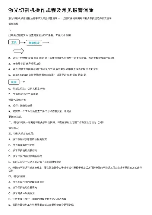
激光切割机操作规程及常见报警消除激光切割机操作规程注意事项及常见报警消除⼀、切割⽂件的调⽤到切割步骤按规范操作流程来操作流程1、找到要切割的⽂件检查属性⾥⾯的⽂件名、⼯件尺⼨调⽤2、选择⼀种厚度设置保存确定是(选择完厚度和材质后⼀定要点设置,否则参数没被调⽤成功)3、 M 全局参数选择喷嘴⼝径4、调光检查主页⾯焦点窗⼝焦点是否为零选中激光喷嘴底下放透明胶带开始按钮5、 origin manger ⾃动搜寻(依据当前位置)设置寻边长度保存确定是6、切割头标定:切割头标定开始7、⽓体测试选中⽓体类型设置⽓压值开始8、运⾏:按启动按钮9、切完第⼀个⼯件之后检查⼯件尺⼨和切割质量,看是否要继续切割。
⼆、调光的时候⼀定要将切割头移到齿板将,切勿在板材上⽅跟⼯作台⾯上⽅出光(以防激光伤⼈)三、切割头标定的应⽤:A、换了不同材质厚度的板材要标定B、换了陶瓷体后要标定C、换了保护镜⽚后要标定D、换了不同⼝径的喷嘴后标定E、切割头在空中抖动不能正常下来切割时要标定F、带膜的不锈钢不能直接标定,要在膜上撕个⼝⼦或者找个薄板⼦标定后⽅可到带膜的不锈钢上⽤定点或者寻边的⽅式进⾏切割四、调光的应⽤:A、换了不同⼝径的喷嘴后要调光B、换了保护镜⽚后要调光C、换了陶瓷体后要调光D、⼯件断⾯三⾯好⼀⾯差的时候要检查光⼼是否跑偏E、碳钢亮⾯切割⼯件切割质量突然变差要检查光⼼是否跑偏F、喷嘴在切割的过程中发⽣猛烈的喷撞,要检查光⼼是否跑偏调光的原理及⽅法:调光的原理实际就是动保护镜⽚其实调节光⼼就是通过拉紧跟松动弹簧来让镜⽚上下左右移动从⽽使光⼼到镜⽚到正中同时⽤内六⾓顺时针拧紧调节螺丝1跟2镜⽚整体往下同时⽤内六⾓逆时针拧紧调节螺丝1跟2镜⽚整体往上调节光⼼出现的8种情况以及如何调节光⼼到正中(1)同时逆时针调节调节螺丝1、2⼀定⾓度到正中位置(2)同时顺时针调节调节螺丝1、2⼀定⾓度到正中位置(3)先逆时针调节调节螺丝2到⼀定⾓度然后再顺时针调节调节螺丝1⼀定⾓度到正中位置(4)先逆时针调节调节螺丝1⼀定⾓度然后再顺时针调节调节螺丝2定⾓度到正中位置(5)同时逆时针调节调节螺丝1、2⼀定⾓度到正左⽅然后先逆时针调节调节螺丝2到⼀定⾓度然后再顺时针调节调节螺丝1⼀定⾓度到正中位置(6)同时顺时针调节调节螺丝1、2⼀定⾓度到正左⽅然后先逆时针调节调节螺丝2到⼀定⾓度然后再顺时针调节调节螺丝1⼀定⾓度到正中位置(7)同时逆时针调节调节螺丝1、2⼀定⾓度到正右⽅然后先逆时针调节调节螺丝1⼀定⾓度然后再顺时针调节调节螺丝2定⾓度到正中位置(8)同时顺时针调节调节螺丝1、2⼀定⾓度到正右⽅然后先逆时针调节调节螺丝1⼀定⾓度然后再顺时针调节调节螺丝2定⾓度到正中位置。
ipg 激光器工作原理
IPG(International Photonics Group)激光器的工作原理基于光
纤激光器的技术。
具体来说,IPG激光器采用了光纤放大器的
原理。
IPG激光器的工作原理涉及到以下几个关键步骤:
1. 光纤耦合:IPG激光器将激光二极管或其他激光源产生的光
通过光纤进行耦合。
光纤是一种具有较高折射率的纤维状结构,可以将光束有效地引导、捕获和传输。
2. 激光增益:经过耦合后,光在光纤中传输。
在光纤中,激发动能将光子转化为光子,并且随着光在光纤中传播,光的数量逐渐增加。
这种现象称为激光增益,通过激增益,光纤中的光强度可以显著增加。
3. 激光放大器:经过激光增益后,光信号被传递到激光放大器。
激光放大器是一种能够对激光信号进行放大的装置。
在激光放大器中,光纤通过受激辐射过程被放大,从而产生高强度的激光束。
4. 输出激光:经过放大后,激光束从激光器的输出端口被释放出来。
这个激光束可以被用于各种应用,如切割、焊接、打孔、医疗等。
总的来说,IPG激光器通过光纤的放大来增加激光信号的强度,并将其输出为高质量、高功率的激光束。
这种激光器具有高效
率、高可靠性和稳定性的特点,被广泛应用于工业和科学研究领域。
IPG激光器接口说明目录1 XP1接口 (2)外部输入信号: (2)激光器输出信号 (3)2 XP2接口 (4)输入信号 (4)3 XP4接口 (5)P1、P2 模拟量输入, 模拟量电压0到10V(对应0-100%功率) (6)4、PA系统激光器通道 (6)第一通道控制激光器功率 (6)5、激光器上高压流程 (7)1 定制产品v1.0 可编辑可修改版本:编写:定制产品部时间:1 XP1接口外部输入信号:Laser Request(激光器请求)高电平有效外部控制时此位必须置1,无此信号输入时其它输入信号都会被忽略。
控制器发出此信号时激光器会发出应答信号,B7(Laser assigned)置为高电平。
A2 Program start (程序启动)高电平有效,控制激光程序起动和停止。
程序号由A8到A14定义。
如果程序号是0000000和A6为高电平,那么激光器由模拟量控制A3 Internal Control Enabled 内控使能,高电平有效A4 Rest error(复位错误)高电平有效复位激光器系统的所有错误信息和激光器输出的错误信号,输入激活时间2 定制产品至少持续1ms。
A5 Guide laser ON (引导激光开启)A6 Analogue control ON(模拟量控制激活)高电平有效激活时程序号要为0000000A16 公共地C1 Laser ON (激光器电源开启)用于打开和关闭激光器主电源,如果主电源不能开启,B13(Warming output)会被置1. 如果主电源开启,输出 B8(Laser ON)会置1.C3至C6 双光纤通道选择 C3 最低位,C6最高位0000→Home position0001→通道10010→通道2激光器输出信号B1 Laser Ready(激光器准备好)高电平有效B2 Emission ON 高电平有效激光器光闸打开,正在出光B3 Internal control enabled 高电平有效内控使能B4 Laser Error(激光器错误)B5 Guide Laser is ON 红光打开时置13 定制产品B6 Analogue Control is ON 模拟量控制模式时置1B7 Laser is assigned 激光器应答信号高电平有效。
.IPG激光器接口说明————————————————————————————————作者:————————————————————————————————日期:IPG激光器接口说明目录1 XP1接口 (4)1.1 外部输入信号: (4)1.2激光器输出信号 (5)2 XP2接口 (6)2.1 输入信号 (6)3 XP4接口 (7)P1、P2 模拟量输入, 模拟量电压0到10V(对应0-100%功率) (7)4、PA系统激光器通道 (7)第一通道控制激光器功率 (7)5、激光器上高压流程 (8)版本:V1.0编写:定制产品部时间:2016.61 XP1接口1.1 外部输入信号:Laser Request(激光器请求)高电平有效外部控制时此位必须置1,无此信号输入时其它输入信号都会被忽略。
控制器发出此信号时激光器会发出应答信号,B7(Laser assigned)置为高电平。
A2 Program start (程序启动)高电平有效,控制激光程序起动和停止。
程序号由A8到A14定义。
如果程序号是0000000和A6为高电平,那么激光器由模拟量控制A3 Internal Control Enabled 内控使能,高电平有效A4 Rest error(复位错误)高电平有效复位激光器系统的所有错误信息和激光器输出的错误信号,输入激活时间至少持续1ms。
A5 Guide laser ON (引导激光开启)A6 Analogue control ON(模拟量控制激活)高电平有效激活时程序号要为0000000A16 公共地C1 Laser ON (激光器电源开启)用于打开和关闭激光器主电源,如果主电源不能开启,B13(Warming output)会被置1. 如果主电源开启,输出 B8(Laser ON)会置1.C3至C6 双光纤通道选择 C3 最低位,C6最高位0000→Home position0001→通道10010→通道21.2激光器输出信号B1 Laser Ready(激光器准备好)高电平有效B2 Emission ON 高电平有效激光器光闸打开,正在出光B3 Internal control enabled 高电平有效内控使能B4 Laser Error(激光器错误)B5 Guide Laser is ON 红光打开时置1B6 Analogue Control is ON 模拟量控制模式时置1B7 Laser is assigned 激光器应答信号高电平有效。
各版本IPG激光器开启外控模式IPG激光器是一种高效率、高可靠性的激光器,常用于工业激光制造、材料加工、医疗和科学研究等领域。
IPG激光器可以通过外控模式来实现灵活的控制和应用。
各版本的IPG激光器开启外控模式的方法和功能略有差异,下面将介绍几个版本常见的外控模式。
首先是IPG激光器的第一代版本,它采用V1.8控制器和固定频率运行模式。
该版本的IPG激光器可以通过开启外控模式来实现干扰、调制和频率变化等功能。
用户可以通过控制器上的开关或软件来切换到外控模式。
在外控模式下,用户可以通过外部信号源来控制激光器的输出功率、脉冲宽度和频率等参数。
IPG激光器的第二代版本采用V2.0控制器,具备更加先进的功能和更高的稳定性。
该版本的激光器开启外控模式的方法与第一代版本相似,但在功能上有所增强。
用户可以通过外部信号源控制激光器的开关、输出功率、频率和脉冲宽度等参数,并且可以实现多种模式的切换和组合。
第三代版本的IPG激光器采用V3.0控制器,进一步提升了控制精度和功能实用性。
该版本的激光器支持外控模式,并采用了数字化的控制方式。
用户可以通过电脑软件、触摸屏或外部信号源来控制激光器的各种参数,包括功率、频率、脉宽、调制方式、光斑形状等。
此外,该版本的激光器还支持网络控制,可以实现多台激光器的联动控制。
除了以上几个常见版本外,IPG激光器还有其他一些特殊版本,如高功率版本、超短脉冲版本和调制版本等,它们的外控模式也有所不同。
高功率版本的IPG激光器通常需要更强的外控能力和更精细的功率调节,而超短脉冲版本的IPG激光器则需要更高的脉冲稳定性和更快的响应速度。
总之,各版本的IPG激光器都支持外控模式,但具体的方法和功能可能有所不同。
用户可以根据不同版本的控制器和用户手册来了解具体的操作步骤和参数设置,并根据实际需求来选择合适的外控模式。
专业资料IPG激光器接口说明目录1 XP1接口 (2)1.1 外部输入信号: (2)1.2激光器输出信号 (3)2 XP2接口 (4)2.1 输入信号 (4)3 XP4接口 (5)P1、P2 模拟量输入, 模拟量电压0到10V(对应0-100%功率) (5)4、PA系统激光器通道 (5)第一通道控制激光器功率 (5)5、激光器上高压流程 (6)版本:V1.0编写:定制产品部时间:2016.61 XP1接口1.1 外部输入信号:Laser Request(激光器请求)高电平有效外部控制时此位必须置1,无此信号输入时其它输入信号都会被忽略。
控制器发出此信号时激光器会发出应答信号,B7(Laser assigned)置为高电平。
A2 Program start (程序启动)高电平有效,控制激光程序起动和停止。
程序号由A8到A14定义。
如果程序号是0000000和A6为高电平,那么激光器由模拟量控制A3 Internal Control Enabled 内控使能,高电平有效A4 Rest error(复位错误)高电平有效复位激光器系统的所有错误信息和激光器输出的错误信号,输入激活时间至少持续1ms。
A5 Guide laser ON (引导激光开启)A6 Analogue control ON(模拟量控制激活)高电平有效激活时程序号要为0000000A16 公共地C1 Laser ON (激光器电源开启)用于打开和关闭激光器主电源,如果主电源不能开启,B13(Warming output)会被置1. 如果主电源开启,输出 B8(Laser ON)会置1.C3至C6 双光纤通道选择 C3 最低位,C6最高位0000→Home position0001→通道10010→通道21.2激光器输出信号B1 Laser Ready(激光器准备好)高电平有效B2 Emission ON 高电平有效激光器光闸打开,正在出光B3 Internal control enabled 高电平有效内控使能B4 Laser Error(激光器错误)B5 Guide Laser is ON 红光打开时置1B6 Analogue Control is ON 模拟量控制模式时置1B7 Laser is assigned 激光器应答信号高电平有效。
IPG北京 高功率激光器夏季操作注意事项 2014-6-12
各位尊敬的用户:
根据经验,夏季是激光器故障高发季节。统计结果显示,高功率激光器大部分故障与用户的
操作顺序及设备运行环境密切相关, 为防止这种情况的出现,减少设备故障时间及其带来的
损失,特提示如下:
一、 可预防故障的产生机理
激光器是将电能转换为激光能的装置,内部构成较为复杂,涉及光,机,电,算等多
个学科和领域。尽管光纤激光器相对其它类型的激光器而言对环境要求较低, 但也
必须保证使用环境符合要求,自身的防护措施能切实起到防护作用。如果开机顺序,
机箱密闭及水温设定等方面存在疏漏,就可能造成激光器内部水冷却的电子和光学器
件因为内外温差导致表面结露,从而降低激光器的性能,乃至损坏激光器。
二、 防范措施
本措施主要是防范内部电子或光学元件结露,具体可分为以下几点:
1. 保证机箱密闭
光纤激光器的机箱采用了密闭设计,并安装了机箱空调或除湿器,其目的是为了
保证机箱内的各个元件处于相对稳定安全的温湿度环境下。如果机箱没有处于密
闭状态, 则机箱外的高温高湿的空气就能进入机箱内部,在遇到内部通水冷却的
元件时,则在其表面遇冷凝结,造成可能的损害。故对机箱密闭性的检查应该注
意以下几个方面:
各机柜门是否存在并关紧
顶部的吊装螺栓是否拧紧
机箱后部未使用的通讯控制接口的保护盖是否盖好,已使用的是否固定好
2. 开机顺序
由于激光器机箱不可能做到完全密闭, 当晚上断电后,机箱空调停止运转,如果
房间没有安装空调或晚间空调不工作,外部的湿热空气可以逐渐渗透进机箱内。
故早上重新开机时,需注意以下操作步骤:
启动激光器总电源(不出光),让机箱空调运行30分钟左右。
IPG北京 高功率激光器夏季操作注意事项 2014-6-12
启动配套的冷水机,等待水温调整到预定温度,激光出光使能。
进行正常加工
建议:如可能,在保证安全的前提下,激光器晚上不断电,让机箱空调保持运行。
或者激光器安装空调房,并保持空调连续稳定运行(包括晚间)
3. 水温设定
冷却水水温对电光转换效率,稳定性及结露有着直接的影响。通常情况下,冷却
水水温设定如下:
自来水(冷却激光器模块)的水温应该设定在21摄氏度左右
针对2500W以上的激光器,去离子DI水(冷却光学件)的水温应该设定在27
度到33度之间,这个温度应根据环境温度和湿度做相应的调整,通常说来环
境温度越高,湿度越大,DI水的水温应该相应增加。其基本原则是DI水水温
应该在结露点以上。结露点表如下:
如有疑问,请拔打IPG售后服务热线400 898 0011寻求帮助。