
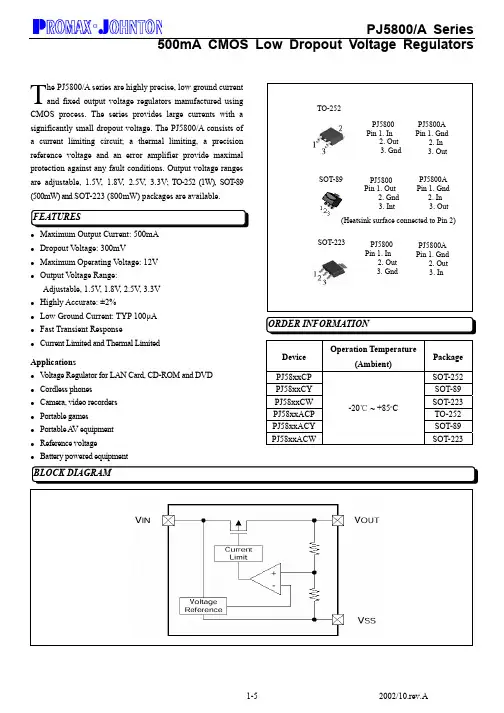
PJ5833CW中文资料
- 格式:pdf
- 大小:237.71 KB
- 文档页数:5
ADC083000ADC083000 8-Bit, 3 GSPS, High Performance, Low Power A/D ConverterLiterature Number: SNAS358NADC0830008-Bit, 3 GSPS, High Performance, Low Power A/D ConverterGeneral DescriptionThe ADC083000 is a single, low power, high performance CMOS analog-to-digital converter that digitizes signals to 8 bits resolution at sampling rates up to 3.4 GSPS. Consuming a typical 1.9 Watts at 3 GSPS from a single 1.9 Volt supply, this device is guaranteed to have no missing codes over the full operating temperature range. The unique folding and in-terpolating architecture, the fully differential comparator de-sign, the innovative design of the internal sample-and-hold amplifier and the self-calibration scheme enable an excellent response of all dynamic parameters up to Nyquist, producing a high 7.0 Effective Number Of Bits, (ENOB) with a 748 MHz input signal and a 3 GHz sample rate while providing a 10-18 Word Error Rate. The ADC083000 achieves a 3 GSPS sam-pling rate by utilizing both the rising and falling edge of a 1.5 GHz input clock. Output formatting is offset binary and the LVDS digital outputs are compatible with IEEE 1596.3-1996, with the exception of an adjustable common mode voltage between 0.8V and 1.15V.The ADC has a 1:4 demultiplexer that feeds four LVDS buses and reduces the output data rate on each bus to a quarter of the sampling rate.The converter typically consumes less than 25 mW in the Power Down Mode and is available in a 128-lead, thermally enhanced exposed pad LQFP and operates over the Indus-trial (-40°C ≤ T A≤ +85°C) temperature range.Features■Single +1.9V ±0.1V Operation■Choice of SDR or DDR output clocking■Serial Interface for Extended Control■Adjustment of Input Full-Scale Range and Offset■Duty Cycle Corrected Sample Clock■Test patternKey Specifications■Resolution8 Bits ■Max Conversion Rate 3 GSPS (min)■Error Rate10-18 (typ)■ENOB @ 748 MHz Input7.0 Bits (typ)■SNR @ 748 MHz44.5 dB (typ)■Full Power Bandwidth 3 GHz (typ)■Power Consumption—Operating 1.9 W (typ)—Power Down Mode25 mW (typ) Applications■Direct RF Down Conversion■Digital Oscilloscopes■Satellite Set-top boxes■Communications Systems■Test InstrumentationOrdering InformationIndustrial Temperature Range(-40°C < TA < +85°C)NS PackageADC083000CIYB128-Pin Exposed Pad LQFPADC083000RB Reference Board© 2009 National Semiconductor C083000 8-Bit, 3 GSPS, High Performance, Low Power A/D ConverterBlock Diagram20 2A D C 020193201Note: The exposed pad on the bottom of the package must be soldered to a ground plane to ensure rated performance. 083000Pin Functions Pin No.SymbolEquivalent CircuitDescription3OutV / SCLKOutput Voltage Amplitude / Serial Interface Clock(Input):LVCMOS Tie this pin high for normal differential DC and data amplitude. Ground this pin for a reduced differentia output amplitude and reduced power consumption. See Sect 1.1.6. When the extended control mode is enabled, this pin functions as the SCLK input which clocks in the serial data. S Section 1.2 for details on the extended control mode. See Section 1.3 for description of the serial interface.4OutEdge / DDR /SDATAEdge Select / Double Data Rate / Serial Data(Input):LVCMOS This input sets the output edge of DCLK+which the output data transitions. (See Section 1.1.5.2). Whe this pin is floating or connected to 1/2 the supply voltage, DD clocking is enabled. When the extended control mode is enabl this pin functions as the SDATA input. See Section 1.2 for det on the extended control mode. See Section 1.3 for description the serial interface.15DCLK_RSTDCLK Reset(Input):LVCMOS A positive pulse on this pin is used to rese and synchronize the DCLK outs of multiple converters. See Section 1.5 for detailed description. When bit 14 in theConfiguration Register (address 1h) is set to 0b, this single-ended DCLK_RST pin is selected. See also pins 22,23description.26PDPower Down(Input):LVCMOS A logic high on the PD pin puts the entire device into the Power Down Mode.30CALCalibration Cycle Initiate(Input):LVCMOS A minimum 80 input clock cycles logic low followed by a minimum of 80 input clock cycles high on this p initiates the calibration sequence. See Section 2.4.2 for an overview of self-calibration and Section 2.4.2.2 for a descript of on-command calibration.14FSR/ECEFull Scale Range Select / Extended Control Enable(Input):LVCMOS In non-extended control mode, a logic low this pin sets the full-scale differential input range to 600 mV P A logic high on this pin sets the full-scale differential input ran to 820 mV P-P . See Section 1.1.4. To enable the extended con mode, whereby the serial interface and control registers are employed, allow this pin to float or connect it to a voltage equ to V A /2. See Section 1.2 for information on the extended con mode. 4A D C 0Pin No.Symbol Equivalent Circuit Description127CalDly / SCSCalibration Delay / Serial Interface Chip Select(Input):LVCMOS With a logic high or low on pin 14, this pin functions as Calibration Delay and sets the number of input clock cycles after power up before calibration begins (See Section 1.1.1). With pin 14 floating, this pin acts as the enable pin for the serial interface input and the CalDly value becomes "0" (short delay with no provision for a long power-up calibration delay).1011CLK+CLK-Sampling Clock Input(Input):LVDS The differential clock signal must be a.c. coupled to these pins. The input signal is sampled on both the rising and falling edge of CLK. See Section 1.1.2 for a description ofacquiring the input and Section 2.3 for an overview of the clock inputs.1819V IN +V IN −Signal Input(Input):Analog The differential full-scale input range is 600mV P-P when the FSR pin is low, or 820 mV P-P when the FSR pin is high. In the Extended Control Mode, FSR is determined by the Full-Scale Voltage Adjust register (address 3h, bits 15:7).2223DCLK_RST+DCLK_RST-Sample Clock Reset(Input):LVDS A positive differerntial pulse on these pins is used to reset and synchronize the DCLK outs of multiple converters.See Section 1.5 for detailed description. When bit 14 in theConfiguration Register (address 1h) is set to 1b, these differential DCLK_RST pins are selected. See also pin 15 description.7V CMOCommon Mode Voltage(Output):Analog - The voltage output at this pin is required to be the common mode input voltage at V IN + and V IN − when d.c.coupling is used. This pin should be grounded when a.c. coupling is used at the analog input. This pin is capable of sourcing or sinking 100μA and can drive a load up to 80 pF. See Section 2.2.083000Pin No.Symbol Equivalent CircuitDescription31V BGBandgap Output Voltage(Output):Analog - Capable of 100 μA source/sink and can dr a load up to 80 pF.126CalRunCalibration Running(Output):LVCMOS - This pin is at a logic high while a calibrat is running.32R EXTExternal Bias Resistor ConnectionAnalog - Nominal value is 3.3k-Ohms (±0.1%) to ground. S Section 1.1.1.3435Tdiode_P Tdiode_NTemperature DiodeAnalog - Positive (Anode) and Negative (Cathode). These p may be used for die temperature measurements, however no specified accuracy is implied or guaranteed. Noise coupling fr adjacent output data signals has been shown to affecttemperature measurements using this feature. See Section 2.6.2. 6A D C 0Pin No.Symbol Equivalent Circuit Description36 / 37 38 / 39 43 / 44 45 / 46 47 / 48 49 / 50 54 / 55 56 / 57 58 / 59 60 / 61 65 / 66 67 / 68 69 / 70 71 / 72 75 / 76 77 / 78Da0+ / Da0-Da1+ / Da1-Da2+ / Da2−Da3+ / Da3-Da4+ / Da4−Da5+ / Da5-Da6+ / Da6−Da7+ / Da7-Dc0+ / Dc0-Dc1+ / Dc1-Dc2+ / Dc2−Dc3+ / Dc3-Dc4+ / Dc4−Dc5+ / Dc5-Dc6+ / Dc6−Dc7+ / Dc7-A and C Data(Output):LVDS Data Outputs from the first internal converter.The data should be extracted in the order ABCD. These outputsshould always be terminated with a 100Ω differential resistor atthe receiver.83 / 84 85 / 86 89 / 90 91 / 92 93 / 94 95 / 96 100 / 101 102 / 103 104 / 105 106 / 107 111 / 112 113 / 114 115 / 116 117 / 118 122 / 123 124 / 125Dd7− / Dd7+Dd6- / Dd6+Dd5− / Dd5+Dd4- / Dd4+Dd3- / Dd3+Dd2- / Dd2+Dd1− / Dd1+Dd0- / Dd0+Db7- / Db7+Db6- / Db6+Db5− / Db5+Db4- / Db4+Db3− / Db3+Db2- / Db2+Db1− / Db1+Db0- / Db0+B and D Data(Output):LVDS Data Outputs from the second internalconverter. The data should be extracted in the order ABCD.These outputs should always be terminated with a 100Ωdifferential resistor at the receiver.79 80OR+OR-Out Of Range(Output):LVDS - A differential high at these pins indicates thatthe differential input is out of range (outside the range ±325 mVor ±435 mV as defined by the FSR pin). These outputs shouldalways be terminated with a 100Ω differential resistor at thereceiver.82 81DCLK+DCLK-Differential Clock(Output):LVDS - The Differential Clock output used to latch theoutput data. Delayed and non-delayed data outputs are suppliedsynchronous to this signal. DCLK is 1/2 the sample clock rate inSDR mode and 1/4 the sample clock rate in the DDR mode.These outputs should always be terminated with a 100Ωdifferential resistor at the receiver. The DCLK outputs may notbe active during the calibration cycle depending upon the settingof Configuration Register (address 1h), bit- 14 (RTD). SeeSection 1.1.1.083000Pin No.Symbol Equivalent Circuit Description2, 5, 8, 13,16, 17, 20,25, 28, 33,128V AAnalog power supply pins(Power) - Bypass these pins to ground.40, 51 ,62,73, 88, 99,110, 121V DROutput Driver power supply pins(Power) - Bypass these pins to DR GND.1, 6, 9, 12,21, 24, 27GND(Gnd) - Ground return for V A .42, 53, 64,74, 87, 97,108, 119DR GND(Gnd) - Ground return for V DR .29,41,52,63, 98, 109,120NC No Connection Make no connection to these pins 8A D C 0(Notes 1, 2)If Military/Aerospace specified devices are required,please contact the National Semiconductor Sales Office/Distributors for availability and specifications.Supply Voltage (V A , V DR ) 2.2VSupply Difference V A - V DR0V to -100mVVoltage on Any Input Pin (Except V IN +, V IN -)−0.15V to (V A + 0.15V)Voltage on V IN +, V IN -(Maintaining Common Mode)-0.15V to 2.5V Ground Difference |GND - DR GND|0V to 100 mVInput Current at Any Pin (Note 3)±25 mA Package Input Current (Note 3)±50 mAPower Dissipation at T A ≤ 85°C 2.3 WESD Susceptibility (Note 4) Human Body Model Machine Model 2500V 250VStorage Temperature−65°C to +150°CSolder i ng process must comply w i th Nat i onal Semiconductor’s Reflow Temperature Profile specifications.Refer to /packaging. (Note 5)Ambient Temperature Range −40°C ≤ T A ≤ +85°C Supply Voltage (V A )+1.8V to +2.0V Driver Supply Voltage (V DR )+1.8V to V A Analog Input Common Mode Voltage V CMO ±50mV V IN +, V IN - Voltage Range (Maintaining Common Mode)0V to 2.15V (100% duty cycle)0V to 2.5V (10% duty cycle)Ground Difference(|GND - DR GND|)0V CLK Pins Voltage Range 0V to V ADifferential CLK Amplitude0.4V P-P to 2.0V P-PPackage Thermal ResistancePackage θJA θJC (Top ofPackage)θJ-PAD(Thermal Pad)128-Lead Exposed PadLQFP26°C / W10°C / W 2.8°C / WConverter Electrical CharacteristicsThe following specifications apply after calibration for V A = V DR = +1.9V DC , OutV = 1.9V, V IN FSR (a.c. coupled) = differential 820mV P-P , C L = 10 pF, Differential a.c. coupled Sinewave Input Clock, f CLK = 1.5GHz at 0.5V P-P with 50% duty cycle, V BG = Floating,Non-Extended Control Mode, SDR Mode, R EXT = 3300Ω ±0.1%, Analog Signal Source Impedance = 100Ω Differential, after cali-bration. Boldface limits apply for T A = T MIN to T MAX . All other limits T A = 25°C, unless otherwise noted. (Notes 6, 7)SymbolParameterConditionsTypical (Note 8)Limits (Note 8)Units (Limits)STATIC CONVERTER CHARACTERISTICS INL Integral Non-Linearity (Best fit)DC Coupled, 1MHz Sine Wave Over Ranged±0.35±0.9LSB (max)DNL Differential Non-Linearity DC Coupled, 1MHz Sine Wave Over Ranged ±0.20±0.6LSB (max)Resolution with No Missing Codes 8Bits V OFF Offset Error-0.20 LSB V OFF _ADJ Input Offset Adjustment Range Extended Control Mode±45 mV PFSE Positive Full-Scale Error (Note 9)−1.6±25mV (max)NFSE Negative Full-Scale Error (Note 9)−1.00±25mV (max)FS_ADJ Full-Scale Adjustment Range Extended Control Mode ±20±15%FS DYNAMIC CONVERTER CHARACTERISTICSFPBW Full Power Bandwidth 3 GHz Word Error Rate10-18 Errors/SampleGain Flatness0.0 to -1.0 dBFS50 to 950 MHz ENOBEffective Number of Bitsf IN = 373 MHz, V IN = FSR − 0.5 dB 7.2 6.8Bits (min)f IN = 748 MHz, V IN = FSR − 0.5 dB 7.0 6.6Bits (min)f IN = 1498 MHz, V IN = FSR − 0.5 dB6.5Bits083000分销商库存信息: NATIONAL-SEMICONDUCTOR ADC083000CIYB/NOPB。
A D9833中文资料高精度可编程波形发生器AD9833中文资料1.AD9833概述AD9833是ADI公司生产的一款低功耗,可编程波形发生器,能够产生正弦波、三角波、方波输出。
波形发生器广泛应用于各种测量、激励和时域响应领域,AD9833无需外接元件,输出频率和相位都可通过软件编程,易于调节,频率寄存器是28位的,主频时钟为25MHz时,精度为0.1Hz,主频时钟为1MHz时,精度可以达到0.004Hz。
可以通过3个串行接口将数据写入AD9833,这3个串口的最高工作频率可以达到40MHz,易于与DSP和各种主流微控制器兼容。
AD9833的工作电压范围为2.3V-5.5V。
AD9833还具有休眠功能,可使没被使用的部分休眠,减少该部分的电流损耗,例如,若利用AD9833输出作为时钟源,就可以让DAC休眠,以减小功耗,该电路采用10引脚MSOP型表面贴片封装,体积很小。
AD9833的主要特点如下:●频率和相位可数字编程;●工作电压为3V时,功耗仅为20mW;●输出频率范围为0MHz-12.5MHz;●频率寄存器为28位(在25MHz的参考时钟下,精度为0.1Hz);●可选择正弦波、三角波、方波输出;●无需外界元件;●3线SPI接口;●温度范围为-40℃-+105℃。
2 AD9833的结构及功能2.1 电路结构AD9833是一块完全集成的DDS(Direct Digital Frequency Synthesis)电路,仅需要1个外部参考时钟、1个低精度电阻器和一个解耦电容器就能产生高达12.5MHz的正弦波。
除了产生射频信号外,该电路还广泛应外于各种调制解调方案。
这些方案全都用在数字领域,采用DSP技术能够把复杂的调制解调算法简化,而且很精确。
AD9833的内部电路主要有数控振荡器(NCO)、频率和相位调节器、Sine ROM、数模转换器(DAC)、电压调整器,其功能框图如图1所示。
AD933的核心是28位的相位累加器,它由加法器和相位寄存器组成,每来1个时钟,相位寄存器以步长增加,相位寄存器的输出与相位控制字相加后输入到正弦查询表地址中。
A D9833中文资料(总6页) -CAL-FENGHAI.-(YICAI)-Company One1-CAL-本页仅作为文档封面,使用请直接删除高精度可编程波形发生器AD9833中文资料1.AD9833概述AD9833是ADI公司生产的一款低功耗,可编程波形发生器,能够产生正弦波、三角波、方波输出。
波形发生器广泛应用于各种测量、激励和时域响应领域,AD9833无需外接元件,输出频率和相位都可通过软件编程,易于调节,频率寄存器是28位的,主频时钟为25MHz时,精度为0.1Hz,主频时钟为1MHz时,精度可以达到0.004Hz。
可以通过3个串行接口将数据写入AD9833,这3个串口的最高工作频率可以达到40MHz,易于与DSP和各种主流微控制器兼容。
AD9833的工作电压范围为2.3V-5.5V。
AD9833还具有休眠功能,可使没被使用的部分休眠,减少该部分的电流损耗,例如,若利用AD9833输出作为时钟源,就可以让DAC休眠,以减小功耗,该电路采用10引脚MSOP型表面贴片封装,体积很小。
AD9833的主要特点如下:●频率和相位可数字编程;●工作电压为3V时,功耗仅为20mW;●输出频率范围为0MHz-12.5MHz;●频率寄存器为28位(在25MHz的参考时钟下,精度为0.1Hz);●可选择正弦波、三角波、方波输出;●无需外界元件;●3线SPI接口;●温度范围为-40℃-+105℃。
2 AD9833的结构及功能2.1 电路结构AD9833是一块完全集成的DDS(Direct Digital Frequency Synthesis)电路,仅需要1个外部参考时钟、1个低精度电阻器和一个解耦电容器就能产生高达12.5MHz的正弦波。
除了产生射频信号外,该电路还广泛应外于各种调制解调方案。
这些方案全都用在数字领域,采用DSP技术能够把复杂的调制解调算法简化,而且很精确。
AD9833的内部电路主要有数控振荡器(NCO)、频率和相位调节器、Sine ROM、数模转换器(DAC)、电压调整器,其功能框图如图1所示。