卓越的SIMARIS软件
- 格式:pdf
- 大小:790.64 KB
- 文档页数:8
射频EDA仿真软件介绍射频EDA(Electronic Design Automation)是一种用于射频芯片设计和仿真的软件工具,它通过电磁场仿真和电路仿真等功能,可以帮助设计者优化射频电路的性能和可靠性。
本文将介绍几款常用的射频EDA仿真软件。
1. ADS(Advanced Design System)ADS是美国Keysight(前身为安捷伦科技)推出的一款强大的射频和微波电路设计和仿真工具。
它包含了多种电路仿真方法,如基于S参数的线性仿真、基于混合EM的电磁仿真和基于直接时间域的高速数字仿真等。
ADS还内置了丰富的器件模型和库,方便用户进行仿真和优化。
此外,ADS还支持与SI/PI和系统仿真软件的集成,使得整个设计流程更加高效。
2. HFSS(High Frequency Structure Simulator)HFSS是美国ANSYS公司开发的一种基于有限元分析(FiniteElement Analysis)的高性能电磁场仿真软件。
它主要用于射频和微波领域,可以模拟复杂的电磁场分布和信号传输。
HFSS具有优异的求解速度和准确度,并且支持多种仿真技术,如频域仿真、时域仿真和混合仿真等。
此外,HFSS还提供了强大的后处理功能,可以用于绘制场强分布图、辐射图和散射参数图等。
3. CST Studio SuiteCST Studio Suite是德国CST公司开发的一款电磁场仿真软件套件,广泛应用于射频、天线和微波电路的设计和仿真。
CST基于有限差分时域(FDTD)方法,具有较高的计算速度和较低的内存占用。
CST StudioSuite提供了丰富的建模功能和后处理工具,可以实现多尺度建模、参数扫描和优化等操作。
此外,CST还支持与ADS和HFSS等软件的数据交换,方便不同工具之间的协同设计和分析。
4. AWR Microwave OfficeAWR Microwave Office是美国National Instruments(前身为奇美电子)开发的一款射频和微波电路设计软件。


GreatSim Works格雷西姆软件工作室Machining数控加工中心仿真软件简明使用手册视频教程下载: /Support1.软件基本操作:机床视图右键菜单介绍:∙ A. XOZ平面:改变机床视图视角∙ B. YOZ平面:改变机床视图视角∙ C. XOY平面:改变机床视图视角∙ D. 隐藏/显示床身:在机床视图中点右键,选择“隐藏床身”或者“显示床身”∙ E. 快速定位:让主轴移动到工件中心位置。
∙ F. 开关机舱门3D机床模型操作:∙ A. 鼠标左键旋转∙ B. 鼠标滚轮放大或缩小∙ C. 按下鼠标中键平移提示窗口:软件菜单介绍∙ A. 加工时间估算加工程序所需时间∙ B. 文件1.导入:导入一个加工程序,但必须在EDIT模式下打开或者新建了一个程序的情况下才能导入2.保存工件:保存已加工工件3.读入工件:打开保存的工件C. 设置∙ 1. 显示刀具轨迹选中后会在自动加工中显示加工轨迹。
2. 显示床身选中该选项将显示床身。
3. 机床声音选中该选项将启用声音效果。
4. 模型阴影选中该选项将启用阴影效果,但是一些比较老的显卡运行速度会下降。
如果速度慢请取消该选项。
∙ D. 视图视图:当面板视图被关闭后,用该菜单将面板重新打开。
双屏显示:分别在两个显示器中显示面板和机床模型。
∙ E. 切换面板各系统间进行切换操作。
∙ F. 设置工件选择工件类型,工件类型为:长方体和圆柱体。
设置工件的显示精度,精度有3级:∙ 1. 性能:工件精度较低∙ 2. 平衡:工件精度中等∙ 3. 质量:工件精度较高请根据显卡能力选择适当的精度,较高的精度资源占用高。
∙G. 检查更新检查是否有新版本,该功能需要联网。
∙H. 帮助文档2. 刀具选择1.新建刀具:添加刀具: 按“Add”按钮添加新的刀具,然后在自定义刀具对话框中输入直径和长度:2 . 编辑刀具:双击“Tool Select”中列表中的条目进行刀具参数编辑。
3 . 删除刀具:按“Delete”按钮删除所选刀具。
Machining Strategist软件:高效数控加工的利器随着制造技术的不断进步,数控机床已经变得越来越普及,并且在制造过程中扮演着越来越重要的角色。
但是,为了充分发挥数控机床的效能,制造企业需要使用优秀的 CAM 工具,以便准确高效地对物料进行加工。
今天我们要介绍的 Machining Strategist 软件正是这样一款工具。
一、软件介绍Machining Strategist 是由英国软件公司 Vero Software 推出的高效数控加工 CAM 软件,其作为 AutoCAD 的插件,支持 STL、IGES 和 VDA 格式的导入,提供了用户友好的图形界面,让用户轻松快速地进行模型处理和程序生成。
该软件具有强大的智能化加工策略,支持钻孔、铣削、车削、线切割、螺纹车削、螺纹铣削等加工方式,可以与国内外大多数数控系统无缝连接,支持机床的刀库和工艺参数。
二、软件特点1.全新的加工策略Machining Strategist 软件提供了全新的、创新的加工策略,包括高速切削、高效精车、高效铣削、高效车削、高效消耗材料的切割和磨削策略。
其中,高速切削可使切削速率高达 10m/min,提高加工效率,精确度也得到了极大的提高。
2.自动化传统加工工艺需要经过许多“手工”处理,包括对数据进行处理、编程过程等。
而 Machining Strategist 软件的出现,将这种“手工”处理变为自动化处理。
通过智能化加工策略,软件可以根据加工材料、形状、大小以及特殊需求等因素,自动生成最佳加工路径和刀具路径,从而使加工过程更加智能和快速。
3.多功能性Machining Strategist 软件具有多种加工方式和策略,包括钻孔、铣削、车削、线切割、螺纹车削、螺纹铣削等,以及多种刀具类型和切削参数的设定,可以通过实际计算再根据个人需求和工业标准,对加工方案进行优化。
同时支持导出 NC 程序、G-code 代码,以及与主流数控系统的接口,如 FANUC、MITSUBISHI、SIEMENS 等。

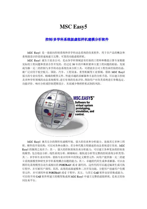
MSC Easy5控制/多学科系统级虚拟样机建模分析软件MSC Easy5是一套面向控制系统和多学科动态系统的仿真软件,用于在产品的概念和系统级设计阶段快速地建立完整、可靠的功能虚拟样机。
MSC Easy5诞生于波音公司,是由各学科领域富有经验的工程师和数值计算专家根据实际的工程问题和需求合作开发的,经过近30年的不断积累和大量工程问题的检验,发展成为独一无二的控制与多学科动态系统仿真分析工具,可谓波音公司工程仿真经验的结晶,被广泛应用于航空航天、国防、汽车、工程设备、重型机械等工业领域。
借助MSC Easy5强大的专业应用库、精确的模型元件、性能卓越的求解器和丰富的分析手段,可以建立控制及多种学科领域的动态系统模型,进行有效的仿真评价,帮助用户对各类系统进行参数选定、功能评价、响应分析或控制逻辑设计,从而减少物理样机试制的风险。
MSC Easy5兼具完全的图形化建模环境、强大的仿真和分析能力、连接其它多种工程软、硬件的开放结构,可以对各种由微分、差分和代数方程描述的动态系统进行仿真。
MSC Easy5的独到之处在于:其一,强大的控制系统仿真分析能力,可以建立各种复杂的控制系统模型,包含稳态分析、线性系统分析、频域响应、根轨迹分析等完整的控制系统分析类型;其二,多学科专业应用库,借助专业应用库中的预定义模型元件,向用户提供独一无二的建立系统级模型和研究多学科系统耦合问题的能力;其三,卓越的代码生成和求解器,可以由图形化系统模型自动生成相应的FORTRAN或C源代码,这些代码可以通过编译生成可执行程序,并可被用户调用;其四,高效的高级建模和二次开发功能,方便用户创建用户化模型元件,并可调用外部FORTRAN或C子程序;其五,与其它CAE软件良好的集成能力,可以将不同CAE软件所建立的模型集成到MSC Easy5中建立完整的虚拟样机,是真正的协同仿真平台。
MSC Easy5的模型元件既包括来自通用控制库的基本数学模块和控制元器件,也包括来自专业应用库的系统级部件。
ANSYS简介开放、灵活的仿真软件,为产品设计的每一阶段提供解决方案通用仿真电磁分析流体力学行业化分析模型建造设计分析多目标优化客户化结构分析解决方案结构非线性强大分析模块Mechanical显式瞬态动力分析工具LS-DYNA新一代动力学分析系统AI NASTRAN电磁场分析解决方案流体动力学分析行业化分析工具设计人员快捷分析工具仿真模型建造系统多目标快速优化工具CAE客户化及协同分析环境开发平台ANSYS StructureANSYS Structure 是ANSYS产品家族中的结构分析模块,她秉承了ANSYS 家族产品的整体优势,更专注于结构分析技术的深入开发。
除了提供常规结构分析功能外,强劲稳健的非线性、独具特色的梁单元、高效可靠的并行求解、充满现代气息的前后处理是她的四大特色。
ANSYS Structure产品功能非线性分析·几何非线性·材料非线性·接触非线性·单元非线性动力学分析·模态分析- 自然模态- 预应力模态- 阻尼复模态- 循环模态·瞬态分析- 非线性全瞬态- 线性模态叠加法·响应谱分析- 单点谱- 模态- 谐相应- 单点谱- 多点谱·谐响应分析·随机振动叠层复合材料·非线性叠层壳单元·高阶叠层实体单元·特征- 初应力- 层间剪应力- 温度相关的材料属性- 应力梯度跟踪- 中面偏置·图形化- 图形化定义材料截面- 3D方式察看板壳结果- 逐层查看纤维排布- 逐层查看分析结果·Tsai-Wu失效准则求解器·迭代求解器- 预条件共轭梯度(PCG)- 雅可比共轭梯度(JCG)- 非完全共轭梯度(ICCG)自然模态·直接求解器- 稀疏矩阵- 波前求解器·特征值- 分块Lanczos法- 子空间法- 凝聚法- QR阻尼法(阻尼特征值)并行求解器·分布式并行求解器-DDS-自动将大型问题拆分为多个子域,分发给分布式结构并行机群不同的CPU(或节点)求解- 支持不限CPU数量的共享式并行机或机群- 求解效率与CPU个数呈线性提高·代数多重网格求解器-AMG- 支持多达8个CPU的共享式并行机- CPU每增加一倍,求解速度提高80%- 对病态矩阵的处理性能优越, ,屈曲分析·线性屈曲分析·非线性屈曲分析·热循环对称屈曲分析断裂力学分析·应力强度因子计算·J积分计算·裂纹尖端能量释放率计算大题化小·P单元技术·子结构分析技术·子模型分析技术设计优化·优化算法- 子空间迭代法- 一阶法·多种辅助工具- 随机搜索法- 等步长搜索法- 乘子计算法- 最优梯度法- 设计灵敏度分析·拓扑优化二次开发特征·ANSYS参数化设计语言(APDL) ·用户可编程特性(UPF)·用户界面设计语言(UIDL)·专用界面开发工具(TCL/TK)·外部命令概率设计系统(PDS)·十种概率输入参数·参数的相关性·两种概率计算方法- 蒙特卡罗法*直接抽样* Latin Hypercube抽样- 响应面法*中心合成*Box-Behnken设计·支持分布式并行计算·可视化概率设计结果- 输出响应参数的离散程度*Statistics* LHistogram* Sample Diagram- 输出参数的失效概率* Cumulative Function* Probabilities- 离散性灵敏度*Sensitivities* Scatter Diagram* Response Surface前后处理(AWE)·双向参数互动的CAD接口·智能网格生成器·各种结果的数据处理·各种结果的图形及动画显示·全自动生成计算报告支持的硬软件平台·Compaq Tru64 UNIX ·Hewlett-Packard HP-UX ·IBM RS/6000 AIX ·Silicon Graphics IRIX ·Sun Solaris·Windows: 2000,NT,XP ·LinuxANSYS MultiphysicsTM MultiphysicsANSYS MultiphysicsTM集结构、热、计算流体动力学、高/低频电磁仿真于一体,在统一的环境下实现多物理场及多物理场耦合的仿真分析;精确、可靠的仿真功能可用于航空航天、汽车、电子电气、国防军工、铁路、造船、石油化工、能源电力、核工业、土木工程、冶金与成形、生物医学等各个领域,功能强大的各类求解器可求解从冷却系统到发电系统、从生物力学到MEMS等各类工程结构。

primes laserdiagnosticssoftware用法primes laserdiagnosticssoftware用法简介primes laserdiagnosticssoftware是一款专业的激光诊断软件,用于分析和控制激光系统的性能。
以下是一些常见的用法,帮助您更好地了解如何使用这个软件。
1. 数据采集•使用primes laserdiagnosticssoftware,您可以轻松地进行激光系统数据的采集。
通过连接激光设备和计算机,并选择合适的数据采集设置,软件将自动开始记录数据。
•通过数据采集,您可以监测激光系统的输出功率、波长、脉宽等参数。
这对于优化激光系统性能和排除问题非常重要。
2. 光谱分析•primes laserdiagnosticssoftware提供强大的光谱分析功能。
您可以将激光系统的波长稳定性和光谱分布进行详细的分析。
•通过观察光谱图,您可以判断激光系统是否存在频率漂移或频率不稳定的问题。
这有助于您及时调整激光系统,并确保其性能的稳定。
3. 波形显示•除了光谱分析,primes laserdiagnosticssoftware还可以显示激光系统的波形。
您可以通过软件界面直观地观察激光脉冲的形状和幅度。
•波形显示功能有助于您了解激光系统的脉宽和脉冲能量分布。
通过比较理论参数和实际波形,您可以判断激光系统是否正常工作,并及时进行调整和优化。
4. 数据分析•primes laserdiagnosticssoftware提供丰富的数据分析工具,帮助您更深入地了解激光系统的性能。
•您可以使用软件内置的统计分析工具来计算激光系统的平均功率、功率分布、功率稳定性等参数。
这些数据对于系统的优化和改进至关重要。
5. 报告生成•利用primes laserdiagnosticssoftware,您可以生成专业的测试报告。
软件支持将数据和分析结果整合成格式化的报告。
•报告生成功能方便您向团队或客户展示激光系统的测试结果和性能评估。

SIMOCRANE integrated STS, GSU Version V3.0These notes take precedence over information in other documents.Please read the notes through carefully because they contain information that it is important for you to know during installation and use of the software.In this version V3.0, the following new features, feature enhancements and feature improvements have been madeSway control functions−New function …Soft Approach“ with consideration of fixed and variable blocked regions in Manual Mode (MAN)−Improving of the function to calculate interpolation points and extending of criterions to start Semi-Automatic Mode (SAM)−Extension of the functional scope of the control bit “START_2D_CALC“−Separated damping factors for acceleration and deceleration (P85, P86, P88, P89)−New parameter (P87) to eliminate the overshooting in positioning process (POS und SAM)−New parameter (P119) for selecting of the lowering point for SAM travel from WS to LS−New parameter (P112, P113) to adapt the trajectory during inclined movement in SAM−Improving of the following error monitoring (E41, E42) for positioning process (POS und SAM) −Expansion of the interface to the higher-level controller (PLC)−New DCC-block “DCC_SCIntPo” to transfer the interpolation points of trajectory to the higher- level controller (PLC)−All camera data will be transferred to the higher-level controller (PLC)−General troubleshooting−Adaption of parameters (Limit values, default value or option)−Extending and improvement of the operation instructions manualsCommissioning and Diagnostic Tool …CeCOMM”−Extending of visualization (limit lines, safety clearance, immersion point…)−Adding the time stamp to the long-time trace−Increasing the number of logger files to 12−New function to calculate the maximum sway deflection−Improvement of the diagram in X/Y-view−Improving of the trace function−Adding a list of all variable signals for trace−TroubleshootingThe Version V3.0 is downwards compatible to the version V 2.1 SP2 HF1. Due to the functional and interface extension, adjustments and new commissioning are required for upgrading. More information about the V2.1 SP2 HF1 refers to the product update for its delivery release:https:///cs/ww/en/view/109750239Contents1. SCOPE OF SUPPLY1.1 DVD1.2 Certificate of License2. NOTES ON INSTALLATION2.1. System requirements2.1.1 Hardware2.1.2 Optional Hardware2.1.3 Software2.2. Installation2.3 Unstalling3. CONSTRAINTS AND FUNCTIONAL RESTRICTIONS1 Scope of Supply1.1 DVDThe DVD contains:The version V3.0 is downwards compatible to the V2.1 SP2 HF1. The software will be put in production and additionally provided for download in internet under ‘Industry Online Support international with Download-ID 109220170, see the following link:https:///cs/ww/en/view/103965095Users can upgrade their application if required. Please pay attention to the preconditions in the operation manual, 07/2019. More information to upgrade your application refer to the FAQhttps:///cs/ww/en/view/109478006Limitation of liabilityThe Software package includes following application examples:•Application example for STS•Application example for GSUThe application example inside the software package are provided free of charge. The customer is granted the non-exclusive, non-transferable, free right to use it. This includes the right to modify the application example, to reproduce it modified or unmodified, and to combine it with the user's own software.All liability, on whatever legal basis, in particular based on errors in the software or the associated documentation or damage resulting from advice, is excluded unless liability is mandatory, for example, due to malice, gross negligence, injury to life, body, or health, due to acceptance of a quality warranty, due to fraudulent concealment of a defect, or due to breach of substantial contractual obligations. This does not imply a reversal of the burden of proof to the detriment of the customer.The customer is furthermore obligated to release SIEMENS AG from any claims of third parties where such claims arise in connection with use of the software by the customer.German law shall apply. The courts of Erlangen shall have exclusive jurisdiction.Safety instructionsSiemens provides products and solutions with industrial security functions that support the secure operation of plants, solutions, machines, equipment and/or networks. They are important components of a holistic industrial security concept. The products and solutions from Siemens are continuously developed with this aspect in mind. Siemens recommends strongly that you regularly check for product updates.For the secure operation of Siemens products and solutions, it is necessary to take suitable preventive action (e.g. cell protection concept) and integrate each component into a holistic, state-of-the-art industrial security concept. Any third-party products that may be in use must also be taken into account. You will find more information about industrial security at: /industrialsecurityConstantly up-to-date information on SIMOCRANE products, product support, FAQs can be found on the Internet: https:///cs/ww/en/ps/200871.2 Certificate of LicenseIn the licensing method used for SIMOTION dependent on the way and number of the runtime components used in the project different licenses must be acquired. The licenses required for a device are assigned to a License key. The license is bound about the serial number of the CF card.The compact flash card (CF card) is not in the scope of supply; a license key must be generated and transferred to the CF card. This will be realized with the help of the enclosed "Certificate of License".Further indications for the license handling will be available in the operating instructions. "SIMOCRANE SC integrated STS, GSU”2 Notes on Installation2.1. System requirementsThe preconditions are a main crane controller system with a PROFIBUS/PROFINET interface as well as continuously controllable drives.Depending on the task to be performed and the environmental conditions, the sway control system can be used with or without a SIMOCRANE CenSOR V2.0 HF3 camera measuring system.The hardware and software required for the camera measuring system must be ordered separately and are not listed here.A version with the necessary hardware components and the required license authority must be available.2.1.1 Hardware• SIMOTION D435-2 DP/PN as of firmware V5.2 SP1 or higher•SINAMICS, as of firmware V5.1.HF1 or higher2.1.2 Optional hardware•SIMOCRANE CenSOR V2.0 HF3•Reflector2.1.3 Software• SIMOTION SCOUT as of Version V5.2 SP1•Optional package Drive Control Chart (DCC) for SIMOTION / SINAMICS as of version V3.1 SP1 •SIMOCRANE Basic Technology Version V3.0•Commissioning and diagnose tool SIMOCRANE CeCOMM ab Version V4.4.2.4•SIMOCRANE SC integrated STS, GSU V3.0•Microsoft Windows 7 or 10•SIMATIC Manager ab V5.62.2. InstallationThe software package contains a setup file. You can use it to install the DCC library "SwayControl." The precondition is that the SIMOTION SCOUT software has been installed and the user is logged onto the PC with administrator rights."Setup_CeCOMM.exe"The installation program leads you step by step through the whole installation process. Installation isperformed as follows:•The SIMATIC Manager and the SCOUT must be closed before the setup is run.•For the procedure for linking the "Sway Control DCC Library" into your SIMOTION user project, see the operating instructions "SIMOCRANE_SC_integrated_STS_GSU_de.pdf" Chapter 5.The software package contains a setup file for the "SIMOCRANE CeCOMM" diagnostics and commissioning tool. The program can run under the WINDOWS 7 or WINDOWS 10 operating system. This requires that the user is logged in the PC with administration rights.Setup_CeCOMM.exeThe installation program guides you through the entire installation process step by step. After installation the diagnostic program will be available under "Windows Start → Programs."2.3UninstallingVia Windows Start →Control panel →Programs, you can uninstall the diagnostics tool installed via setup.3. Constraints and functional restrictionsMethod of operation P140 (3525253)P140 must be left as 0.Function of the P77 (3534325)Leave the parameter P77 with its default value (200).Function of the parameters P149 and P150 (3555469)Leave the parameters P149 and P150 with their default values (0).Function of the P111 (752485)An Adjustment of 0 or 1 for P111 causes no smoothing. Between these values decreasingvalues lead to an increasing smoothing. Values smaller than 0,1 should be avoided. Thesmoothing has no influence to the closed-loop control and effects only the display of the trace in CeCOMM.Workaround: Leave the parameter P111 with its default value (0).P53 Acceleration reduction when hoisting (751425)With values of the parameter P53 < 100 %, unexpected acceleration behaviour of the hoist may occur.Workaround: Parameter P53 must be left with its default value (100%).Warning messages E20 to E27 (1002665)Warning messages E20 to E27 do not work. Functioning of the prelimit switch and limit switchmust be assured in the higher-level control.Target control function (301654)In the case of the hoist and trolley, the target control function results in the target always beingtraveled to with a deviation from P162 or P165 (positioning accuracy). Parameters P163 andP160 must not be less than 0 if the target is to be traveled to without this deviation.Workaround: Do not set parameters P163 and 160 smaller than 0.Stopping a cylinder movement in operation mode “Cylinder jogging”As a result of incorrect Position sensing it may happen that despite correct control according to the operation instructions the movement of the Cylinder cannot be stopped.Workaround: By resetting of the control bit …move“ the cylinders can be stopped ev en in case of incorrect positon sensing (without down ramp).The time-optimal control algorithmus is not used for STS-cranes.Workaround: The time-optimal control algorithmus (P152) should not be used for STS-cranes(P102=1).Operation mode …Cylinder jogging“As a result of incorrect Position measurement it may happen thatDespite correct control according to the operation instructions the movement of the Cylindercannot be stopped.Despite of the selection of only one cylinder more cylinders are moving at the same time.Workaround:By resetting of the control bit …move“ the cylinders can be stopped even in case of incorrectpositon sensing (without down ramp).With an interlock (in PLC) of the state bits …a_out“ up to …d_out“ and …a_in“ up to …d_in“(Zyl inder retract and extend) with the corresponding control bit …a_in_comm“ up to…d_in_comm“ and …a_out_comm“ up to …d_out_comm“ it is possible that only the selectedcylinder is moving.Trolley uncontrolled acceleration (4310214)Trolley uncontrolled acceleration.Abhilfe:Use the delivered new application project.End。
现在的高速电路设计已经达到GHz的水平,高速PCB设计要求从三维设计理论出发对过孔、封装和布线进行综合设计来解决信号完整性问题。
高速PCB设计要求中国工程师必须具备电磁场的理论基础,必须懂得利用麦克斯韦尔方程来分析PCB设计过程中遇到的电磁场问题。
目前,Ansoft公司的仿真工具能够从三维场求解的角度出发,对PCB设计的信号完整性问题进行动态仿真。
(一)Ansoft公司的仿真工具现在的高速电路设计已经达到GHz的水平,高速PCB设计要求从三维设计理论出发对过孔、封装和布线进行综合设计来解决信号完整性问题。
高速PCB设计要求中国工程师必须具备电磁场的理论基础,必须懂得利用麦克斯韦尔方程来分析PCB设计过程中遇到的电磁场问题。
目前,Ansoft公司的仿真工具能够从三维场求解的角度出发,对PCB设计的信号完整性问题进行动态仿真。
Ansoft的信号完整性工具采用一个仿真可解决全部设计问题:SIwave是一种创新的工具,它尤其适于解决现在高速PCB和复杂IC封装中普遍存在的电源输送和信号完整性问题。
该工具采用基于混合、全波及有限元技术的新颖方法,它允许工程师们特性化同步开关噪声、电源散射和地散射、谐振、反射以及引线条和电源/地平面之间的耦合。
该工具采用一个仿真方案解决整个设计问题,缩短了设计时间。
它可分析复杂的线路设计,该设计由多重、任意形状的电源和接地层,以及任何数量的过孔和信号引线条构成。
仿真结果采用先进的3D图形方式显示,它还可产生等效电路模型,使商业用户能够长期采用全波技术,而不必一定使用专有仿真器。
(二)SPECCTRAQuestCadence的工具采用Sun的电源层分析模块:Cadence Design Systems的SpecctraQuest PCB信号完整性套件中的电源完整性模块据称能让工程师在高速PCB设计中更好地控制电源层分析和共模EMI。
该产品是由一份与Sun Microsystems公司签署的开发协议而来的,Sun最初研制该项技术是为了解决母板上的电源问题。
应用SimDesigner提高悬架DMU仿真准确性叶锦文;王建宜;吴保玉;王瑞林【摘要】The authors introduce how to replace joints with bushings to get a more accurate DMU model of the sus-pension. Then by inputting mass property of parts in the model, by changing parameters of the elastic elements and adjusting balance position of the model, they make the model more accurate and consistent with the true vehicle. At last, they compare and analyze the simulation results of SimDesigner and CATIA.%介绍在SimDesigner软件中应用衬套代替运动副的方法,建立更加准确的悬架DMU模型,通过设置零件重量参数、弹性件参数、调整静平衡位置,提高模型的准确性,使模型与实际尽量相符合,最后对比分析SimDesigner与CATIA的仿真结果。
【期刊名称】《客车技术与研究》【年(卷),期】2015(000)001【总页数】4页(P16-19)【关键词】悬架;SimDesigner;DMU;仿真【作者】叶锦文;王建宜;吴保玉;王瑞林【作者单位】广州汽车集团股份有限公司汽车工程研究院,广州 510640;广州汽车集团股份有限公司汽车工程研究院,广州 510640;广州汽车集团股份有限公司汽车工程研究院,广州 510640;广州汽车集团股份有限公司汽车工程研究院,广州 510640【正文语种】中文【中图分类】U463.33汽车底盘零部件互不干涉是汽车安全行驶和具备舒适性的基本条件之一。
石 化 专 栏2014年第1期128西门子石化行业配电解决方案柴淑云 何友林(西门子基础设施与城市业务领域中低压集团,北京 100102)1 西门子石化配电解决方案概述西门子全集成能源管理(Totally Integrated Power ,TIP )为石化行业提供全集成配电解决方案,主要基于以下3个方面。
1)西门子向客户免费提供专用工具软件,为配电系统规划设计提供强有力的支持。
通过SIMARIS 设计软件,用户可方便、快速、可靠的计算配电网络的全部电气参数,按计算结果自动选择和整定保护电器,评价选择性保护配合,有助于设计和管理人员对配电系统整体和局部能耗的透明化管理。
2)提供了高效、可靠的全系列配电产品和系统,覆盖从中压开始到低压主配电、分配电一直到末端配电。
可组成安全可靠的配电解决方案,适用石化行业高端配电系统的应用。
3)对石化配电系统可实现信息化的集成功能,通过多功能智能仪表、智能断路器,智能开关柜等配电产品的灵活多样的通信方式,实现能源监控和管理,并可集成到企业的自动化系统当中。
2 石化行业配电系统特点石化行业具有电力负荷密度大、供电可靠性要求高等特点。
石化工厂必须取到可靠的电源,应根据地区供电的具体情况确定工厂的供电方式,大中型工厂可采用外供电的方式, 也可采用外供电和自发电的综合方式。
大型石化工厂一般由两个以上独立的电源供电。
大型石化企业的 35/6(10)kV 配电网,系统中性点多采经电阻接地方式;在低电压侧,接地类型的选择也决定了系统的电磁兼容性。
石油化工生产装置 0.38/0.22kV 配电系统接地形式应采用 TN-S 系统。
石化行业配电设计时还要考虑变频器、UPS 等造成的谐波影响。
当平均功率因数低于当地供电局要求时,应装设无功功率补偿装置。
并根据无功功率的分布情况,经技术经济比较来确定集中补偿或分散补偿方案。
3 高效的石化行业配电系统设计西门子SIMARIS 设计软件自动计算和选型节省电气设计师大量的工作量,确保配电设计高效,配电系统安全、可靠。
Package‘simfit’October14,2022Type PackageTitle Test Model Fit with SimulationVersion0.1.0Maintainer James Green<*****************>Description Simulates data from model objects(e.g.,from lm(),glm()),and plots this along with the original data to compare how well thesimulated data matches the original data to determine modelfit.Imports magrittrDepends R(>=2.10),ggplot2License GPL-3Encoding UTF-8LazyData trueRoxygenNote7.1.1Suggests testthat(>=3.0.0)Config/testthat/edition3NeedsCompilation noAuthor James Green[aut,cre](<https:///0000-0002-7309-0751>)Repository CRANDate/Publication2021-05-1707:30:12UTCR topics documented:pred.fit (2)pred.plot (2)sim.plot (3)symptom (4)Index612pred.plot pred.fit Fit Simulated Data to a Model.DescriptionFit Simulated Data to a Model.Usagepred.fit(model,xpred=NULL,ci=0.95,npoints="same")Argumentsmodel a model object,from(eg)lmxpred the predictor for the x axis on the graphci confidence interval forfit curve(defaults to0.95)npoints number of data points forfit line.Either specify a number,or"same"will returna simulation of the same size as the original dataset.Valuepredicted dataExamples##Anwar M,Green JA,Norris P,et al##Prospective daily diary study reporting of any and all symptoms in healthy##adults in Pakistan:prevalence and# response##BMJ Open2017;7:e014998data(symptom)glm.symptom<-glm(actual_help_days~symp_days_reported,family="poisson",data=symptom)pred.fit(glm.symptom)pred.plot Add modelfit line(with SE)to GLM models(Poisson,negative bino-mial etc)DescriptionAdd modelfit line(with SE)to GLM models(Poisson,negative binomial etc)Usagepred.plot(model,xpred=NULL,ci=0.95)sim.plot3Argumentsmodel a model object,from(eg)lm glmxpred the predictor to be plotted on the x axisci value for confidence interval(defaults to0.95)Valueggplot object withfit lineExamples# ##Anwar M,Green JA,Norris P,et al##Prospective daily diary study reporting of any and all symptoms in healthy##adults in Pakistan:prevalence and# response##BMJ Open2017;7:e014998data(symptom)glm.symptom<-glm(actual_help_days~symp_days_reported,family="poisson",data=symptom)pred.plot(glm.symptom)sim.plot Plot simulated data from a GLM modelDescriptionPlot simulated data from a GLM modelUsagesim.plot(model,xpred=NULL,seed=NULL,fit.line=TRUE,ci=0.95,npoints="same",orig_jitter=0.1,sim_jitter=0.1)Argumentsmodel a model object,from(eg)lm glm(Poisson,Negative binomial)xpred the predictor to be plotted on the x axisseed random seed so that simulation results are replicablefit.line if TRUE(default)addsfit line with SEci passes confidence interval width forfit curve(defaults to0.95)npoints number of data points to forfit line.Either specify a number,or"same"will return a simulation of the same size as the original dataset.orig_jitter amount of jitter to apply to original dataset(default0.10)sim_jitter amount of jitter to apply to simulated data(default0.10)Valueggplot object with simulated data plotted with originalExamples##Anwar M,Green JA,Norris P,et al##Prospective daily diary study reporting of any and all symptoms in healthy##adults in Pakistan:prevalence and# response##BMJ Open2017;7:e014998data(symptom)glm.symptom<-glm(actual_help_days~symp_days_reported,family="poisson",data=symptom)sim.plot(glm.symptom)symptom Responses to symptoms from a sample of the general population ofPakistan.DescriptionA dataset containing the age,gender,number of days on which symptoms were experienced,num-ber of days on which help was sought,as well as measures of impulsivity and attitudes to medicines. UsagesymptomFormatA data frame with53940rows and10variables:id participant ID,integerage5age in5year bins,(18,20)(20,25)(25,30)(30,35)(35,40)(40,45)(45,50)(50,55)(55,60) (60,65)gender female,male,characterbmq_spec Pakistan adaption of Beliefs about Medicines Questionnaire(Specific)Stored as POMP score0-100bmq_necess Pakistan adaption of Beliefs about Medicines Questionnaire(Necessity)Stored as POMP score0-100bmq_concern Pakistan adaption of Beliefs about Medicines Questionnaire,(Concern)Stored as POMP score0-100bmq_general Pakistan adaption of Beliefs about Medicines Questionnaire,(General)Stored as POMP score0-100bis Pakistan adaption of Barratt Impuslivity Scale,Stored as POMP score0-100symp_days_reported Number of days on which symptoms were reported,Non-negative integer (days)actual_help_days Number of days on which participants visited some type of health professional, Non-negative integerSourcehttps://osf.io/4mjhq/data from Anwar M,Green JA,Norris P,et al Prospective daily diary study reporting of any and all symptoms in healthy adults in Pakistan:prevalence and#’response BMJ Open2017;7:e014998 doi:10.1136/bmjopen2016014998Index∗datasetssymptom,4pred.fit,2pred.plot,2sim.plot,3symptom,46。
simcenterflomaster的help文件(最新版)目录1.Simcenter Flomaster 简介2.Simcenter Flomaster 的功能3.Simcenter Flomaster 的应用领域4.Simcenter Flomaster 的安装与使用5.Simcenter Flomaster 的帮助文件正文Simcenter Flomaster 是一款由西门子公司开发的流体多物理场仿真软件,它集成了多个领域的仿真技术,包括流体动力学、热传导、固体力学等。
用户可以通过该软件进行复杂的流体多物理场仿真,以模拟和预测现实世界中的流体行为。
Simcenter Flomaster 具有丰富的功能,包括以下几个方面:首先,Simcenter Flomaster 具有强大的几何建模功能,用户可以轻松创建复杂的三维几何模型。
此外,软件还支持从其他 CAD 软件中导入模型,方便用户进行仿真。
其次,Simcenter Flomaster 提供了丰富的物理模型,包括流体动力学模型、热传导模型、固体力学模型等。
用户可以根据自己的需求选择合适的模型进行仿真。
再次,Simcenter Flomaster 具有强大的求解器,可以高效地解决复杂的多物理场问题。
同时,软件还提供了多种求解方法,包括稳态求解、瞬态求解、非线性求解等,以满足不同用户的需求。
Simcenter Flomaster 的应用领域非常广泛,包括汽车工程、航空航天、能源电力、工业制造等。
用户可以通过该软件进行流体多物理场仿真,以优化产品设计、提高产品性能、降低产品成本。
对于如何安装和使用 Simcenter Flomaster,用户可以参考软件的官方文档或者在线教程。
同时,Simcenter Flomaster 还提供了丰富的帮助文件,包括本文档,以帮助用户更好地理解和使用软件。
总之,Simcenter Flomaster 是一款强大的流体多物理场仿真软件,它集成了多个领域的仿真技术,具有丰富的功能和应用领域。
1SimGEN软件1.1Spirent仿真系统简介1.1.1GSS6700仿真系统的组成GSS6700是Spirent公司在2008年推出的新型GPS仿真产品。
GSS 6700是一个系列产品的代号,它替代停产的STR4500(回放功能)和GSS6560(实时仿真)这两种不同功能的产品,同时将可以仿真的星座类型扩展到GPS、GLONASS 和Galileo。
GSS6700仿真系统组成如下图:图4-1:GSS6700 仿真系统组成图1.1.1.1组成部分1.GSS6700 信号源;2.信号源控制计算机;3.仿真控制软件。
1.1.1.2GSS6700信号源的性能参数- 星座类型:GPS/SBAS星座;- 码类型:GPS L1 & SBAS L1 C/A ;- 通道数:12通道,同时最多可仿12可导航星信号;- 信号动态范围:相对速度±15,000 m/s,相对加速度±450 m/s2,相对加加速度±500m/s3;- 电平控制范围:+15~-20dB;- 信号电平参考基准:-160dBW;- 信号的电平仿真精度:0.5dB(区别与控制分辨率0.1dB);- 伪距的仿真精度:±0.002 m;- USB总线与仿真软件控制计算机通信;1.1.1.3GSS 6700配套的仿真软件GSS 6700仿真系统由购买时候厂商提供的软件和License决定仿真系统的功能。
GSS 6700对应有三种不同名称的仿真控制软件:SimPLEX V3.01:SimReplayPlus;SimGEN。
SimPLEX V3.01和SimReplayPlus配套只能回放仿真场景,其中SimReplayPlus能修改仿真的起始时间。
SimPLEX V3.01仿真软件,仅能播放SimGEN仿真软件生成的后缀为.sim文件,以驱动仿真器产生动态GPS射频信号。
若仿真控制软件为SimGEN,则厂商根据用户的要求,提供相应的License 文件,License文件与仿真信号源一一对应,决定整个仿真系统的功能。